Jun 7, 1997 - Computers. H.A. James, Craig J. Patten and K.A. Hawick. {heath,cjp ..... Some examples are the red-black solver algorithm used for diffusion problems or ..... of the 3d Ising Modelâ Clive F. Baillie, Rajan. Gupta, Kenneth A.
Technical Note DHPC-010.
Stencil Methods on Distributed High Performance Computers H.A. James, Craig J. Patten and K.A. Hawick {heath,cjp,khawick}@cs.adelaide.edu.au Department of Computer Science, University of Adelaide, Adelaide, SA 5005, Australia 7 June 1997 Abstract
Various distributed I/O methods for retrieving the image data were also examined in this work, including the use of RAID and ATM technology, and these are discussed in section 5.
We describe a distributed computational infrastructure for applying kernel operators on arbitrary images. Our primary use for this is the processing of GMS-5 satellite imagery, although there are many possible applications in the areas of general image processing, cellular automata, computational physics and the direct solving of partial differential equations, among others. We discuss the issues involved in implementing our framework using the data parallel and message passing paradigms, and provide and discuss performance data for our message passing implementation using MPI/MPICH. In this work we also perform initial investigations into the various distributed I/O issues involved in performing such tasks on a network of workstations with RAID and ATM technology, and provide and discuss results.
Performance measurements are given in section 6 and they are discussed in section 7. Sections 8 and 9 give conclusions and describe the future work to be undertaken on this project.
2
In this section we describe the images that make up the mainstay of the applications that we will be processing using the infrastructure. We currently obtain satellite imagery from the Japanese GMS-5 satellite [11], and store the data on the DHPC 1 Data Repository [7, 8]. This satellite provides visible spectra and Infra-Red (IR) spectra data for a large region of the earth including Australia.
Keywords: Parallel and distributed computing, image processing, distributed I/O, ATM, RAID.
1
GMS Data
The Geostationary Meteorological Satellite (GMS) provides more than 24 full hemisphere multichannel images per day. The channels and resolution are shown in Table 1. Channel Wavelength Resolution (µ m) (km) Visual 0.5 - 0.75 1.5 Thermal IR 1 10.5 - 11.5 5.0 Thermal IR 2 11.5 - 12.5 5.0 Water Vapour IR 3 6.5 - 7.0 5.0
Introduction
This document describes a distributed computational infrastructure for applying a series of kernel operators, also known as stencils, on arbitrary images. We believe that the current hardware and software technologies available to us can be integrated together to provide a framework for distributed image processing and a distributed remote sensing library.
Table 1: GMS-5 VISSR Channels
In this paper, we describe this computational infrastructure, and the components of such an infrastructure. The stencils and the origin of the images which will constitute the main application will be discussed, as will the methods of parallel and distributed implementation.
Each image is 2291x2291 pixels; information in IR images are 8-bits and VIS images are 6-bits, cor1 The Distributed High Performance Computing (DHPC) Project is funded by the Research Data Networks Cooperative Research Centre (RDN CRC)
1
responding to grey-scale levels. Resolution is approximately 4.5km squared. Although we are currently primarily working with GMS data, we are also investigating the future possibility of working with larger, more complex meteorological datasets.
3
Kernel/Stencil Methods
Stencil methods, or convolution, is a generic image processing operation [10]. Convolving an image involves the following steps: 1. A moving window is created that contains an array of coefficients or weighting factors. Such arrays are referred to as operators or kernels or stencils; they are normally an odd number of pixels in size (eg., 3x3, 5x5, 7x7). 2. The stencil is moved throughout the original image, and the pixel value at the centre of the stencil in a second (convoluted) output image is obtained by multiplying each coefficient in the kernel by the corresponding pixel value in the original image and adding all the resulting products. This operation is performed for each pixel in the original image. Stencil methods are widely used in many direct solution methods for partial differential equations as well as in many cellular automaton and other models in computational physics and also for many simple image processing algorithms. The key feature of stencil based applications is their use of relatively localised data on a regular mesh to update individual variables on the mesh. For example, the very simple Forward Time Centred Space solution of the Laplace Equation involves the discretisation of the field variable ψ on a mesh of some dimensionality - we use a 2d mesh here for illustration - and the iterative update of values ψi,j according to: ψi,j = ψi+1,j + ψi−1,j − 4ψi,j + ψi,j+1 + ψi,j−1 (1) A number of image processing operators can be expressed as simple kernel operations or ‘stencils’. Individually these stencil operations are relatively simple in computational structure and are generally applied to an image or other field-based data using a simple loop over each data value and its neighbouring values as specified by the stencil. Similarly, models in computational physics such as the Ising (bit variables), Potts (integer variables) or Heisenberg (floating point vector) spin models, involve simulation of spin systems on a regular mesh
whereby the update rule for each spin variable is a simple formula based on the present value of the mesh variable and the values of its neighbours. 0
0
0
0
0
6
3
0
0
6
3
0
6
0 -5
3
0
8
1
0
8 -25 7
1
0
0 0
0
0
Data field before
8
1 0
Data field after 1
Stencil Operator
1 -4 1
1
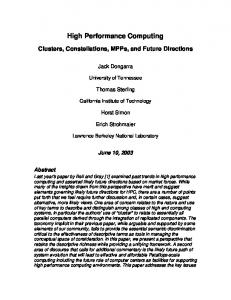
Figure 1: Application of 5-point stencil operator to 2d data field This is illustrated in figure 1, showing a 5-point stencil operator (the central point and its four nearest neighbours on a 2d square mesh) applied to a data field of integer values. Stencil operators find uses in applications such as solving partial differential equations using finite difference methods. The stencil operator in figure 1 corresponds to a central difference formulation of the ∇2 operator. More complex stencils can be constructed for various image processing operations. For example, edge detection or convolution. For 2 dimensional images, each stencil is a 2d image itself, with values that are not necessarily integer in value. It is convenient to adopt the convention that the stencils are constructed as centred with an odd length of edge, although stencils need not be square and may be rectangular. The idea generalises to higher dimensions and allows volume stencils to operate on voxel data on a regular mesh. Application of stencil Sk,l to an image Ii,j might be expressed as: X Ii,j 7→ Sk,l · Ii,j (2) k,l
for each pixel value (i, j) in image Ii,j . While the stencil operation simply produces a linear summation of each pixel value and its neighbouring values, weighted by the corresponding stencil elements, some additional specification is necessary to define this operation at the boundary pixel values. For the purposes of manipulating images, it is convenient to assume all terms corresponding to pixel values outside the image are set to zero. This is not necessarily the case for a stencil operation used to solve a partial differential equation where the data field may be chosen to have cyclic boundaries or some value other than zero.
These operations are often not computationally very intensive, especially for relatively small stencils. The computational cost of looping over pixel values may be comparable to the cost of doing the arithmetic on modern computational systems. It is possible to construct stencil operations that are not linear however, and where each stencil element is a functional rather than a simple weight.
is 9N2 . If these two 3x3 stencils are composed, then the resulting stencil will be of dimensions 5x5, and will contain up to 25 non-zero elements. Imposing the resultant stencil on the image will cause a maximum of 25N2 operations to be performed, which is clearly greater than the number required to apply the stencils serially.
It is interesting to consider how such operations can be decomposed on a parallel architecture. Consider a number Np or processors in a parallel architecture (or processes on a virtual machine - we do not distinguish in this work).
If there are six stencils to be applied, all 3x3, the maximum number of operations for this serial application would be 54N2 . If the six stencils were composed, the resulting stencil would have dimensions 13x13, and the number of operations required would be at most 169N2 .
The task to be performed may consist in general of a sequence of n stencil operators to be applied to an image, written as:
However, there are two situations in which we believe stencil composition may be more efficient than serial application.
Sknn ,ln · · · Sk22 ,l2 · Sk11 ,l1 · Ii,j
If the system was under the restriction of only being able to apply a single stencil to the piece of the image, and had to communicate to retrieve and send back the resulting image, it may be beneficial to compose all the smaller stencil operations.
(3)
where the summations over each successive stencil’s size are implicit.
3.1
Stencil Optimisation
The model of computation that we are using is one in which each slave has equal access to the stencils, and indeed, loads each stencil into an internal array before applying them on their piece of the image. Two approaches to applying stencils on images were performed. The first method involved directly applying each stencil on the image in turn. This means that if there are N stencils, the image is modified N times. The second method tried was to compose the stencils that were to be applied on the image into a single, functionally equivalent stencil, and to apply this to the image. Composing stencils involves noting the order in which the stencils would be applied to the image (or piece of the image), and then creating a resultant stencil by successively applying the stencils to each other in that order. (Note that if the stencils are non-linear, with functionals as elements, they must be applied in strict order and no associativity relation can be used to compose them.) For the reason that each slave directly loads the stencil(s) to be applied, and that each slave’s segment of the image is broadcast and retrieved by the master once only, we found no direct benefit in our situation by composing stencils within this framework, as described below. This is shown by considering two stencils, each 3x3, which are to be imposed on an image of size NxN. Each stencil contains 9 elements, and as some of the elements my be zero, the maximum number of operations that would be performed on the image
Also, if the image that the stencil was to be applied to was larger than the physical or cache memory of the slave machine, the act of cycling through the image data may cause many cache misses, hence decreasing performance. Although this effect would still be present when imposing a composed stencil on the large image, the effect would be exacerbated with the serial application of the smaller stencils.
4
Parallel Implementations
A serial implementation of the stencil application was first written in C [9]. We then parallelised it using the MPICH [4] implementation of MPI [5], on a network of DEC Alpha workstations. A data parallel implementation, the issues for which are detailed in the next section, is under development.
4.1
Data Parallelism
High Performance Fortran (HPF) provides a means of expressing the data parallelism in stencil problems. HPF is particularly well suited to stencil problems since it provides a number of mechanisms for the communication of neighbouring data values on regular meshes. Equation 1 can be expressed in the following code (figure 2). & &
psi = cshift(psi,1,1) + cshift(psi,-1,1) + cshift(psi,1,2) + cshift(psi,-1,2) + 4.0 * psi
Figure 2: HPF / Fortran 95 code fragment
This shows the use of the CSHIFT intrinsic function which shifts (cyclically - ie wrapping round at the boundaries) the data by ±1 in the data dimension stated. In cases where the application calls for non-periodic boundary conditions, the FORALL statement may be more appropriate. Figure 3 shows how an explicitly parallel construct may be used to set up the update rule for interior points. Additional code sections can be used for the boundary values. forall(i=2:m-1,j=2:n-1) psi(i,j) = psi(i+1,j) + psi(i-1,j) & 4.0 * psi(i,j) + & psi(i,j+1) + psi(i,j-1) end forall
Figure 3: Laplace update expression in terms of FORALL statement. In general the mesh variable data would be distributed across the processors’ memories in BLOCK fashion for such an application. Providing the data array was significantly larger in size than the number of processors, then the actual communications needed to move data across processor boundaries would be low. Most mesh points would be in fact interior to the processors own memory. For some applications, however it is necessary to carry out the mesh updates in a particular order. Some examples are the red-black solver algorithm used for diffusion problems or another well know case is that of Monte Carlo models in computational physics where the update algorithm requires updating alternate mesh variables in each dimension at once. Generally this reduces the parallelism by a factor of two, but since mesh sizes are (usually) much larger than the number of processors, this does not affect the exploitable parallelism. HPF provides a suitable mechanism for distributing a red-black checkerboard update. The BLOCK data distribution - or CRINKLE mapping as it was originally known when first implemented on the Distributed Array Processor (DAP) in the early 1980’s - allows the data to be ‘blocked’ across the processors’ memories and thus updates to be ordered to suit the applications algorithm while still exploiting data locality. This allows each processor to own a share of ‘red’ and ‘black’ mesh points and therefore to participate in every stage of the computation - maximising the parallel activity. Figure 4 illustrates the distribution for (BLOCK,BLOCK) where all processors have some red and some black, and (CYCLIC,CYCLIC) where there will be a load imbalance with some processors inactive during each colour stage.
Figure 5 illustrates how red-black ordering can be done using a FORALL statement. Two separate FORALL constructs are used for the ‘red’ and ‘black’ interleaving meshes. Note the use of stride 2 to construct the red-black ordering. In this example only the interior points are dealt with. Separate code would be needed to loop over the edge points to ensure the correct boundary conditions were applied. forall(i=2:m-1:2,j=2:n-1:2) psi(i,j) = psi(i+1,j) + psi(i-1,j) & 4.0 * psi(i,j) + & psi(i,j+1) + psi(i,j-1) psi(i+1,j+1) = psi(i+2,j+1) + psi(i,j+1) & 4.0 * psi(i+1,j+1) + & psi(i+1,j+2) + psi(i+1,j) end forall forall(i=2:m-1:2,j=2:n-1:2) psi(i+1,j) = psi(i+2,j) + psi(i,j) & 4.0 * psi(i+1,j) + & psi(i+1,j+1) + psi(i+1,j-1) psi(i,j+1) = psi(i+1,j+1) + psi(i-1,j+1) & 4.0 * psi(i,j+1) + & psi(i,j+2) + psi(i,j) end forall
Figure 5: Red-Black Laplace update expression in terms of FORALL statement. A similar stride structure can be used to construct other more complex mesh ‘colour’ groupings, such as are used for Monte Carlo simulations where longer range interactions are involved. All of the above is general for one, two, three or higher dimensional data structures, and the only major changes are the data distribution directives. Another technique that can be used where a more complicated or data dependent mask is used to create different col-or order sub meshes is the HPF WHERE construct. For example a logical masking array can be used to mask out active/inactive elements of the mesh. Intrinsic functions like MERGE may also be used to conditionally combine components of a partial calculation into a final result for updating the mesh. This approach is particularly useful if an application requires an update such as a red-black one in combination with a data dependent one such as the Swendsen-Wang or Wolff cluster updating procedure for spin models [1, 2]. In this case, normal Metropolis updates require a CSHIFT or FORALL construct, whereas the cluster update identities some subset of the mesh variables to be updated conditionally and the WHERE is needed. Some interesting tradeoff situations occur when applications use more complex stencil operations with longer range communications. The Cahn-Hilliard equation is used to phase transitions in binary alloys [6] and is formulated as:
1
2
3
4
1
1
1
2
2
3
3
4
4
i.
2
3
4
ii.
Figure 4: Red-Black mesh i. distributed (BLOCK,BLOCK) and ii. distributed (CYCLIC,CYCLIC) on 4x4 processor grid.
� ∂φ = m∇2 −bφ + uφ3 − K∇2 φ ∂t
(4)
where the field variable φi,j is on a regular mesh as before, but since the equation involves ∇2 (∇2 ), the update procedure requires next and next-next nearest neighbouring mesh point data. This can either be formulated explicitly in terms of a single update line using some 20 CSHIFT operations as shown in figure 6 or an intermediate data variable can be used to reduce this to only 8 CSHIFTS as shown in figure 7. This represents a clear tradeoff between memory and communications speed. For a very large size of simulated mesh, memory may be at a premium even in a parallel computer with a lot of distributed memory and the slower communications-intensive algorithm may be preferred. Interestingly, the physics of the problem is such that the natural intermediate variable is a free-energy like quantity and may be of interest as an intermediate calculated quantity in its own right.
4.2
Message Passing
Message passing is a paradigm for parallelism which is perhaps not as well-suited to stencil operations as data parallelism, since grid operations cannot be specified as easily. However, the Message Passing Interface (MPI) allows the programmer to abstract over low-level network communications, to the point where domain decomposition over a mesh can be relatively straightforward. The MPI standard has also been widely adopted on many high performance platforms, from massively parallel computers to networks of workstations. This ensures the portability of our message-passing stencil code.
phi = phi + dtby2 * ( & & -16.0 * phi & & + 7.0 * & & ( cshift(phi, 1,1) + cshift(phi, 1,2) & & + cshift(phi,-1,1) + cshift(phi,-1,2) ) & & - ( cshift(phi, 2,1) + cshift(phi, 2,2) & & + cshift(phi,-2,1) + cshift(phi,-2,2) ) & & -2.0 * & & ( cshift(cshift(phi, 1,1), 1,2) & & + cshift(cshift(phi, 1,1),-1,2) & & + cshift(cshift(phi,-1,1), 1,2) & & + cshift(cshift(phi,-1,1),-1,2) ) & & -4.0 * phi ** 3 & & + ( cshift(phi, 1,1)**3 + & & cshift(phi, 1,2)**3 & & + cshift(phi,-1,1)**3 + & & cshift(phi,-1,2)**3 ) & & )
Figure 6: Cahn-Hilliard Equation Direct Solution - Memory-efficient, communications-inefficient. f = 3.0 * phi ( cshift(phi,1,1) + cshift(phi,-1,1) + cshift(phi,1,2) + cshift(phi,-1,2) ) + phi ** 3 phi = phi + dtby2 * & ( cshift(f,1,1) + cshift(f,-1,1) + & cshift(f,1,2) + cshift(f,-1,2) -4.0 * f) & & &
& & & & &
Figure 7: Cahn-Hilliard Equation Direct Solution Memory-inefficient, communications-efficient. (f is an intermediate mesh variable) Our implementation of the general stencil infrastructure using MPI uses a master-slave paradigm, where the image to be processed is split into N approximately equal chunks, to be spread over N slave processes, probably on N processors. As stated earlier, performing these tasks for a stencil computation using the message passing paradigm is not as easily specified as it is when using the data parallel paradigm. An example of this effect is the need
for more explicit specification as to the handling of boundary conditions in the message passing case. These occur at two different levels in the parallel application of stencils. Firstly, at the boundary of the entire image, where our implementation assumes all outside pixels have zero value. However, boundary conditions are also encountered by the slave processes at the very boundaries imposed by domain decomposition, the boundaries between individual image sections. To solve this problem, a halo is calculated for a given image according to the stencils that are to be applied to it. This halo, of which there is one per slave process, contains image data surrounding that to be processed by that particular slave. The number of surrounding pixels required by a slave is dependent on the size of the stencil(s) to be applied - a 3x3 stencil only requires adjacent pixels, whereas a 5x5 stencil requires data from two pixels away from the pixel currently being processed. Halos are effectively read-only data as far as most slave processes are concerned, except in the solitary slave process where the pixels are actually live data and not a halo. When executed, our stencil application program first refers to a configuration file, which details: • The I/O method to be used to access the subject image; for more information on this see section 5, • The filenames of the subject image, and the resultant image, and • The file(s) specifying the stencil(s) to be applied. The next step is to retrieve the image data, detailed in section 5. Once each slave has retrieved its part of the data, including any necessary halo data for the specified stencils, the stencils are performed serially. We have not yet developed a technique for the slaves to use to merge their data in parallel once the application of the stencil(s) has completed. Therefore, they currently all send their resultant imagery to the master slave using MPI calls. The master then writes the output image to the specified file.
5
Image I/O
• The master process simply passes control information to the slaves, specifying the image file the slaves should load, and the section that each of them is to process; note that this method requires a shared file space, and • The master process predistributes the subject image data across all slave processors’ individual file spaces, and then passes control information to the slave processes in the same fashion as the previous method, pointing the slaves at the local data. The third technique is, of course, equivalent to the second apart from the filesystem being accessed. We have distinguished between them in this work to show any performance difference between using a shared file space, in our case a RAID accessed by NFS V3 over an OC3c ATM link, and a local scratch disk. This is in anticipation of future research into distributed hierarchical file stores where ensuring “the right data is in the right place at the right time” will be essential for performance. Performance data for these three methods are shown in section 6 and discussed in section 7.
6
Performance
All performance measurements were made on DEC Alpha workstations, networked over OC3c ATM. Figures 8, 9 and 10 show the performance of the stencil application code when used with 1, 2, 4 and 8 stencils, on a 1024x1024 image, using the various image data retrieval techniques described in section 5. Figure 11 shows the performance of a solitary stencil operator on a quite larger image, 3072x3072 pixels, using the three different image retrieval methods. Note that in all of the experiments illustrated, the number of processors specified are only those performing stencil calculations. i.e. The master process, which itself does not perform the stencil calculations, is not included.
7
Discussion
The first results to note are those in figures 8, 9 and 10 - two main observations can be made:
There are currently three methods we have explored for the image data retrieval, in a preliminary investigation into distributed storage and I/O:
• The speedup obtained with our MPI stencil application is close to linear, but the overhead in our implementation begins to dominate as the number of processors rises, thus decreasing the speedup achieved, and
• The master process loads the image, and distributes it across its N slaves using MPI functions,
• Similar results were obtained from all three image data retrieval mechanisms: sending with MPI, using local disk, and using remote RAID.
6
6 1 stencil 2 stencils 4 stencils 8 stencils 1:1 speedup
1 stencil 2 stencils 4 stencils 8 stencils 1:1 speedup
4
4
Speedup
5
Speedup
5
3
3
2
2
1
1 1
2
3
4 Number of processors
5
6
7
Figure 8: Speedup data for stencil operations on 1024x1024 image data, where the master sends to slaves
1
2
3
4 Number of processors
5
6
7
Figure 10: Speedup data for stencil operations on 1024x1024 image data, where the slaves use NFS over ATM
6
2.8 1 stencil 2 stencils 4 stencils 8 stencils 1:1 speedup
Broadcast Local Disk Remote RAID 1:1 speedup
2.6
5
2.4
2.2
Speedup
Speedup
4 2
1.8
3 1.6
1.4
2
1.2
1
1 1
2
3
4 Number of processors
5
6
Figure 9: Speedup data for stencil operations on 1024x1024 image data, where the slaves use local disk The first of the above two points shows two unsurprising facts: the application of stencils to images is quite parallelisable, and that Amdahl’s Law is evident in these experiments. In this case, using more than 5 processors for applying 1 or 2 stencils to an 1024x1024 image does not achieve much, if any, speedup: the program execution is being dominated by non-parallelisable overheads. The reason behind the second of the points is perhaps not so obvious until figure 11 is examined, where we concentrate on the application of one stencil to a rather large image - nearly an order of magnitude larger than the previous images in terms of the number of pixels. The performance difference between the three image retrieval mechanisms is clearly visible in this graph. The “broadcast” method is currently a relatively poor performer with large images because of the
7
1
2
3
4 Number of processors
5
6
Figure 11: Speedup data for one stencil operator on 3072x3072 image data way the image data is distributed to the slave processes. The image chunks are sent to the slave processes one-by-one, so that slave processes must block and wait for those “before” them, in terms of rank, to receive their chunks, before receiving their own. This wastes CPU cycles, although this cost does not appear until the images become rather large. Future work may include optimising this implementation.
8
Conclusion
We have developed and described a general distributed infrastructure for applying stencils to arbitrary image data. Our results show that the problem is easily and successfully parallelisable even when using message passing rather than data parallelism. We have also discussed different methods for the application of stencils, and the storage and
7
distribution of subject data. We have also highlighted various related areas, further described in section 9, in which research is required.
[5] “Using MPI: Portable Parallel Programming with the Message-Passing Interface”, W. Gropp, E. Lusk, A. Sjkellum, Pub. MIT Press, ISBN 0-262-57104-8, 1994.
9
[6] “Domain Growth in Alloys”, Kenneth A. Hawick, PhD Thesis, Edinburgh University, 1991.
Future Work
Future work will involve the extension of this simple framework to a larger, more flexible package, which is able to handle the convolution of multiple images simultaneously (ie treating all four channels of a GMS dataset as a single image, and performing convolutions on all), and the provision of a suitable user interface, thus enabling the dynamic selection, application, and generation of stencils. We also have yet to complete a data parallel implementation of our package to compare with the message passing implementation. Further investigation can also be performed into various mesh/grid libraries, such as PUL-RD [3], which are built on top of message passing implementations to facilitate similar functionality to what our package uses. Further research into the “data at a distance” paradigm is required, and locally we are working in this area by researching distributed high-performance hierarchical stores and filesystems.
10
Acknowledgements
We thank Francis Vaughan for useful ideas and discussion thereof, Telstra for provision of the Experimental Broadband Network and NASA and the Japanese Meteorological Agency for provision of the GMS-5 satellite data. The authors acknowledge the support provided by the Research Data Networks and Advanced Computation Systems Cooperative Research Centres (CRC) established under the Australian Government’s CRC Program.
References [1] “Quenching 2d Quantum Gravity”, C.F.Baillie, K.A.Hawick and D.A.Johnston, Physics Letters B 328 (1994) 284-290. [2] “Monte Carlo Renormalisation Group Study of the 3d Ising Model” Clive F. Baillie, Rajan Gupta, Kenneth A. Hawick, G. Stuart Pawley, Physical Review B 45 (1992) 10438-10453. [3] “PUL-RD Prototype User Guide”, Edinburgh Parallel Computing Centre, 1996. [4] “A High-Performance, Portable Implementation of the MPI Message Passing Interface Standard”, W. Gropp, E. Lusk, N. Doss, A. Sjkellum, Pub. Argonne National Laboratories.
[7] “Geographic Information Systems Applications on an ATM-Based Distributed High Performance Computing System”, K.A. Hawick, H.A. James, K.J. Maciunas, F.A. Vaughan, A.L. Wendelborn, M. Buchhorn, M. Rezny, S.R. Taylor and M.D. Wilson. Accepted for HPCN, Vienna, Austria, 1997. Also DHPC Technical Report DHPC-003. [8] “Geostationary-Satellite Imagery Applications on Distributed, HighPerformance Computing”, K.A. Hawick, H.A. James, K.J. Maciunas, F.A. Vaughan, A.L. Wendelborn, M. Buchhorn, M. Rezny, S.R. Taylor and M.D. Wilson. Accepted for HPC Asia, Seoul, Korea, 1997. Also DHPC Technical Report DHPC-004. [9] “The C Programming Language”, B.W. Kernighan and D.M. Ritchie, 2nd Ed, Pub. Prentice Hall, New Jersey, 1988. [10] “Remote sensing and image interpretation ”, T.M. Lillesand and R.W. Kiefer, 3rd Ed, Pub. John Wiley and Sons, Inc., 1994. [11] “The GMS User’s Guide”, Pub. Meteorological Satellite Center, 3-235 Nakakiyoto, Kiyose, Tokyo 204, Japan. Second Edition, 1989. [12] “Getting started with HDF - User Manual”, NCSA, University of Illinois at UrbanaChampaign, May 1993.