Popular exam- ples are Java ME [16], Android SDK [17], and the Apple iPhone SDK [18]. Our ..... PTR (2004). 17. DiMarzio, J.: Android: A Programmer's Guide.
Strategies for Visualizing Points-of-Interest of 3D Virtual Environments on Mobile Devices Matthias Trapp, Lars Schneider, Norman Holz, J¨ urgen D¨ollner Hasso-Plattner-Institute, University of Potsdam Prof-Dr.-Helmert-Str. 2-3, 14482 Potsdam, Germany
Abstract. 3D virtual environments are increasingly used as generalpurpose medium for communicating spatial information. In particular, virtual 3D city models have numerous applications such as car navigation, city marketing, tourism, and gaming. In these applications, pointsof-interest (POI) play a major role since they typically represent features relevant for specific user tasks and facilitate effective user orientation and navigation through the 3D virtual environment. In this paper, we present strategies that aim at effectively visualizing points-of-interest in a 3D virtual environment used on mobile devices. Here, we additionally have to face the ”keyhole” situation, i.e., the users can realize only a small part of the environment due to the limited view space and resolution. For the effective visualization of points-of-interest in 3D virtual environments we propose to combine specialized occlusion management for 3D scenes together with visual cues that handle out-of-frame points-of-interest. We also discuss general aspects and definitions of points-of-interest in the scope of 3D models and outline a prototype implementation of the mobile 3D viewer application based on the presented concepts. In addition, we give a first performance evaluation with respect to rendering speed and power consumptions.
1
Introduction
Since mobile devices and gadgets have become an important part of our daily life, one can observe an growing number of of mobile devices, such as Pocket PCs, navigation systems, and mobile phones, as well as their applications. These devices decrease in size, whereas their performance and feature set has been improved. Based on the increased rendering capabilities, mobile navigation and gaming starts to shift from the second into the third dimension. Therefore, there is a strong demand for visual exploration of 3D virtual environments information using mobile devices. Due to their nature, mobile devices suffer from small screen size and limited input capabilities. Hence, the challenge is an appropriate visualization of 3D models and efficient navigation techniques especially suitable for 3D geovirtual environments (GeoVE). In contrast to 2D visualization, visualization of POIs in 3D virtual environments on mobile devices has to deal with the following challenges:
2
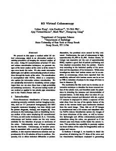
Fig. 1. Example of a 3D Halo Projection visualization combined with occlusion management showing three landmarks. One landmark is on the left side out-of-view (arc). One landmark is marginally within the view (circle), but occluded by another building (which is therefore rendered using a wire-frame style). One landmark is in the right half-space behind the camera (straight line).
– Occlusion: Introducing the third dimension often leads to occlusion of important scene objects by occluding objects. This occurs especially in the pedestrian’s view perspective. An effective visualization for landmarks should handle occlusions properly. – Perspective: Interactive visualization of 3D virtual environments must perform effectively under varying perspectives. We distinguish mainly between three settings: the pedestrian’s, bird’s eye, and plan view. – Scene Complexity: Due to the limited computing and memory capacity on mobile devices, a management of the scene geometry and textures is necessary. This paper presents the following contributions to the reader: – We propose an extended POI notion that is especially suitable for 3D GeoVE. – We introduce a POI visualization concept for mobile navigation and gaming applications that can be applied under changing perspectives. In particular, we focus on managing the occlusion effect for maintaining the POI’s visibility. – We briefly describe the implementation of our approach on a specific mobile device using a scene-graph based rendering system. We further provide a performance evaluation with respect to the rendering speed and power consumptions using virtual environments of different geometric complexity. The remainder of this paper is structured as follows: Section 2 reviews related work on the topic of POI visualization and interactive rendering on mobile devices. Section 3 introduces an extended POI notion. Section 4 presents our ap-
3
proach for an effective visualization of POI in 3D GeoVE on mobile devices. Section 5 gives a brief overview of the implementation of our rendering technique. Section 6 presents the results of our approach and discusses its performance as well as its problems and limitations. After presenting suggestions for future work, Section 7 concludes this paper.
2 2.1
Related Work Visualization of Points-of-Interest
Gustafson et al. [1] as well as Burigat et al. [2] classify off-screen awareness approaches into Overview+Detail and Focus+Context visualization techniques. Overview+Detail Visualization approaches use an additional window that displays a survey knowledge of the current scenery. In the context of 3D GeoVE, simplified and minified views are common that show the scenery as plain 2D map. A major drawback of Overview+Detail is the additional cognitive task performed by the user to map between the information of both detail and overview screen [3, 1]. The second drawback, the Level-of-Detail (LOD) of the overview screen, is especially crucial when dealing with large-scale virtual environments [3]: using a high LOD an overview map might not cover all POIs, whereas omitting too much detail could hamper the users’ orientation. Further, an overview screen requires additional screen space that is limited on mobile devices [1]. Focus+Context Visualization techniques do not rely on additional windows and visualize all information in a single view. All objects within the view center are in focus and all surroundings represent the context. Gustafson et al. [1] further distinguish between distorted views and non-distorted, contextual views. Employing a distorted view, objects in focus are visualized clear and sharp whereas the context is distorted. The transition between focus and context areas is typically smooth. A popular visualization is the fisheye view [4]. Such visualizations have disadvantages in targeting or re-visitation tasks, due to the distorted visualization [5]. Hence, these views are finitely suitable for spatial related task as they occur in 3D GeoVE. Non-distorted, contextual views do not aim to visualize all context information. Non-distorted, contextual views visualize POIs with abstract shapes that are overlaid on screen. For an off-screen POI an abstract shape acts as proxy to visualize the POI’s existence. In virtual environments these proxies indicate traditionally direction and distance of the associated POI. Popular visualization techniques are Arrows [2], City Light [6], and EdgeRadar [7]. Partially-out-of-the-frame Visualization exploits the human visual system for proxy recognition and interpretation. All approaches described above, rely on an explanation or legend for the user to interpret the abstract shape. These
4
explanations require either screen space or have to be memorized by the user. To overcome these problems, Baudisch and Rosenholtz introduced the 2D Halo visualization [8]. Distance and direction are implicitly conveyed by circles around POIs, that reach into the viewport. These partly visible circles are automatically completed through amodal completion conducted by the human visual system. The user get an intuitive imagination of the POI’s distance and direction. This partially-out-of-the-frame approach is borrowed from cinematography [9]. The benefit is an intuitive and efficient visualization of distance and direction. Nevertheless, for a high number of POIs, the Halo visualization suffers from cluttering induced due to overlapping arcs. To reduce cluttering Gustafson et al. introduced Wedge visualization [1]. A Wedge is an acute isosceles triangle in which the tip coincides with the off-screen POI and the two other corners are on-screen. Consequently, the triangle legs are partly visible and the user is able to determine distance and direction of the associated POI. The overlapping is reduced by the distance- and direction-independent adjustment of the Wedge’s opening angle and its rotation around the POI. However, Wedges suffer from overlapping and cluttering, too, if the number of POIs is further increased. Besides the off-screen awareness, visualization of POIs has to deal with the problem of occluded on-screen POIs. In [10] Elmqvist et al. identify several occlusion management patterns for reoccurring occlusion problems based on their taxonomy of occlusion management techniques. 2.2
Interactive Rendering on Mobile Devices
Playing 3D games, exploring, and navigating through 3D virtual environments is already possible on mobile devices [11]. Due to the limitations in screen size, battery power and rendering hardware, the obtainable rendering performance is not comparable to those of modern desktop systems. Consequently, visualization applications developed for desktop environments do not scale well for mobile devices [12]. However, the m-LOMA project [13] presents a 3D engine that performs rendering of 3D city models at interactive rates from any viewpoint, discuss optimization principles, a system architecture, as well as describes a user study. 3D mobile maps provide realistic visualization of objects, a high degree of free movement and a volumetric representation of space. The assets and drawbacks of 3D maps in comparison to 2D maps, which are commonly installed on modern mobile devices, are presented by means of a user study and discussed in [14]. In [15], a rendering technique for interactive direct volume visualization on mobile devices is presented and limitations of mobile graphics devices are discussed.
3
A Concept for Adaptive Points-of-Interest
While experimenting and implementing different 3D on- and off-screen visualization techniques, we discovered a lack of precision in the term POI, which is further elaborated in this section. At first we highlight different perceptions of
5
the term found in literature. Afterwards, we propose a more precise definition suitable for visualization of POIsin 3D GeoVE. 3.1
A Common Problem for Points-of-Interests in 3D
The notion POI classifies objects into either interesting or not interesting with respect to a given context. In case of 3D GeoVE, these are 3D objects of a specific feature type, such as buildings, roads, or street furniture. Here, the context is usually navigation and the POI can be considered as navigation targets. The purpose of an off-screen location visualization technique is to point to the interesting objects which are outside the current view frustum. Existing approaches such as Arrows, Halos, or Wedges require therefore an exact point representation for every object to be applied correctly. Vendors of navigation systems, often store a fixed 2D georeferenced position (in WGS84) for each POI, such as the access and exit points for a gas station. Other objects, such as complex buildings, are represented by its geometrical center point. Mostly, this is sufficient in case an object is small, relative to its context, has a convex shape, and no major extend along one of the coordinate axis. In 2D space, a circle should furthermore reasonably approximate the shape of the object. Examples on a 2D map are the position of a person, a road intersection, or a house. Given an arbitrary position of a virtual camera, objects with specific extend along an axis, e.g., walls or roads, are not sufficient represented by static geometrical center point. In 3D space this problem becomes more difficult due to the additional dimension because every shape of an object must be reasonable approximated, e.g., using a sphere. Objects with an appropriate point representation in 2D space, e.g., a skyscraper with quadratic basement for instance, have no such point in 3D space. 3.2
Dynamic Anchor Points
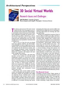
To handle the above problem, we propose the terms Appropriate-RepresentationPoint (ARP) and Cloud-of-Interest (COI) to specify the unsharp term POI. An ARP is a geometrically point, that represents an object at its best with respect to a given scene from a certain camera perspective. A COI is a set of all possible ARPs (Pi ) of an object. Therefore, we introduce two functions: δ and σ. The function δ computes a COI for a given object. The function σ selects an ARP out of an object’s COI for a given scene and camera situation: δ(Object) = {P1 , P2 , . . . , Pn } = COIObject σ(scene, activeCamera, COIObject ) = ARP ∈ COIObject The two functions δ and σ are application specific, change at run-ime, and can be adapted accordingly. For example, in the context of a 3D virtual city model, a COI can be defined as a line along a main axis of an object: for an object with a principal horizontal form, a horizontal COI through its center can be selected. (Figure 2). See Section 4.1 for more details on these functions.
6
Fig. 2. A (bird’s view) and B (pedestrian’s view) visualize two different AppropriateRepresentation-Points (ARPs), selected from the same Cloud-of-Interest (COI), respectively the same object. The skyscraper’s COI (A,B) is a straight line from the center of the basement to the center of the rooftop (main axis of the building). In contrast to that, C depicts a COI and an ARP of a long and flat building.
4
Visualization of Points-of-Interests
This section presents three visualization approaches that can be used to emphasize a POI within 3D GeoVE. Two of these techniques visualize POIs which are not within the view frustum, hence off-screen. Both techniques rely on on-screen proxy objects that represent the off-screen POI. Therefore, we apply the 2D Halo concept described in Section 2.1 to the screen space and introduce a new world space visualization. We further, combine both techniques with a simple form of occlusion management for POIs that are are on-screen, but occluded by less important objects. All visualization techniques require an exact 3D point that is determined by a dynamic anchor point concept introduced in Section 3.2. 4.1
Designing Visual Cues
While designing visual cues for 3D off-screen locations we identified the following ambition: The main objective is the users’ intuitive understanding of distance and direction, relative to the camera position, of an off-screen POI. Since every off-screen POI is visualized by means of an on-screen proxy, it is important to enable the user to be aware of this correlation. In this context it is especially difficult to design a proxy that communicates a POI behind the camera. In case of more than one POI, a proper differentiation between the respective onscreen proxies is required. An additional task is to ensure that these proxies are not significantly occluded by scene objects. Furthermore, these proxies have to have as less viewport coverage as possible to minimize visual clutter and thus maximize the user’s perception of the currently visible scene.
7
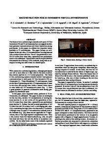
Fig. 3. The left side shows the radius determination of a 3D Halo Circle (the resulting circles are omitted due to clarity). On the right the 3D Halo Projection technique is illustrated. The circle C around PP reaches into the area B, limited by an intrusion border, to help the user estimating the out-of-view distance and direction of PA .
3D Halo Circle visualizes off-screen locations by means of two equal circles around an ARP parallel to a reference plane that approximates the virtual 3D model. One circle is rendered above and the other one underneath the ARP on an axis-aligned line through the ARP (Figure 4). The ARP is selected with a σ function that selects that point out of the COI based on the minimal distance to the view frustum center. The radius for both circles is determined as follows: At first, a line PA PC between ARP PA and view frustum center PC is probed against all frustum planes to find an intersection (Figure 3). In case the ARP is within the frustum, hence (potentially) visible, no intersection has occurred. Otherwise, an intersection point PI is found. Using this point and frustum intrusion depth � ∈ R+ , the circle radius r is determined by the formula: r = euclidianDistance(PA PC ) + �.
3D Halo Projection visualizes off-screen locations with a circle around the projection of an ARP (Figure 1) on the projection plane. This reduces the 3D space problem to a 2D space problem. The point with the minimal distance to the Point-of-View is selected as ARP by a σ function from the COI. The ARP is projected onto the projection plane. In case the projection point PP is outside of a defined viewport border B, a circle C is drawn around PP with a radius large enough to tangent B. Based on the visible arc, a user is able to estimate, i.e., the out-of-view distance and direction of the ARP (Figure 3). This notion of distance is a major difference to 2D Halo visualization and 3D Halo Circle approach. The 3D Halo Projection distance notion gives a user an impression how far a certain object is out-of-view. This is considered rather an
8
advantage than a disadvantage since spatial orientation is an important task in 3D virtual environments. 4.2
Occlusion Management
Occlusion is a common phenomenon when navigating in a 3D environment. Offscreen POIs are free of occlusion since they are visualized by proxy objects, which should not be occluded by scene objects. In contrast, distant on-screen POIs can be occluded by nearby objects, the so-called occluder, and are thereby invisible for a user. To ensure this property, we apply an occlusion management approach to counterbalance this phenomenon. Therefore, our approach turns occluding surfaces invisible or semi-transparent in order to maintain POIs visibly. This concept is summarized by the Virtual X-Ray Pattern [10]. This pattern is usually implemented using image-based approaches, whereas occlusion is determined on a per-pixel basis. Unfortunately, the image-space approach is currently unavailable to most of mobile devices due to the missing support for programmable shaders. Consequently, we intermediately manage occlusion in object-space by omitting the rendering of the occluder or changing its rendering style, e.g., to wire-framed.
5
Implementation
This section briefly introduces the technologies our interactive rendering implementation is based on. Third party development on mobile devices is enabled by device specific Software Development Kits (SDKs) that provide typically a high abstraction to the device hardware and the windowing system. Popular examples are Java ME [16], Android SDK [17], and the Apple iPhone SDK [18]. Our exemplary implementation is based on the Apple iPhone SDK and the iPhone as testing device. As a state-of-the-art multimedia device, it is capable of rendering 3D graphics fully hardware accelerated using a dedicated graphics processing unit (GPU) and possesses a capacitive multi touch screen. The hardware accelerated rendering is accessed through the low-level Application Programming Interface (API) OpenGL ES Version 1.1 [19]. OpenGL ES is a subset of OpenGL [20] especially suited for mobile devices. Based on OpenGL ES, a rudimentary scene-graph system has been implemented to provide the scene management facilities for the proposed visualizations. The POI visualization and occlusion management are encapsulated in so-called techniques that traverse the scene graph and process the scene objects accordingly. The traversal is implemented according to the Visitor pattern [21]. The pseudo-code in Algorithm 1 exemplifies the handling of the currently visited object within the scene graph scene and a given camera activeCamera. The technique pre-traverses the scene graph and sets the corresponding flags for removal or wire-frame rendering of an object according to a preprocessed visibility test. These flags are considered in the subsequent rendering traversal and the scene objects are rendered accordingly. The visibility test determines
9
Algorithm 1 Visualization of Points-of-Interest 1: 2: 3: 4: 5: 6: 7: 8: 9: 10: 11: 12: 13: 14:
if viewFrustumCulling(object, activeCamera) then for all visible POI do if occlude(object, P OI, scene, activeCamera) then cull(object) or changeStyleAndRender(object) {Section 4.2} else render(object) end if end for else if isPOI(object) then σobject = selectSigmaFunction(object) δobject = selectDeltaFunction(object) ARP = σobject (scene, activeCamera, δobject (object)) {Section 3.2} renderHalo(object, ARP ) {Section 4.1} end if
for every visible object whether it occludes a POI or not. It is based on a rayintersection test [22] between the axis-aligned bound box (AABB) that is derived from the tested mesh and the rays constructed from the current view-point to a visible POI. Leveraging the semantics of 3D geovirtual environments, we exclude the ground meshes from this visibility test.
6
Results & Discussion
This section discusses the visualization techniques, described in Section 4, and a performance analysis of the used 3D scene graph engine. 6.1
Application Scenarios
3D Halo Circle enables the user to determine the off-screen POI distance and direction by extrapolation of a complete circle out of the partly visible circle curve (Figure 4, left). POIs, that are on-screen, are also emphasized using the 3D Halo Circle approach (Figure 4, middle small).An asset of 3D Halo Circle is the visualization of POIs behind the virtual camera. In such case, the user has the impression of being within the circle (Figure 4, middle) which is consistent with the visualization the user would naturally expect. The visualization of more than one POI leads to visual clutter, due to the high number of lines. The different circles will cause a certain level of distraction and it is hard to distinguish between the circle pairs of a POI. Moreover, as the circle radius increases, i.e., the POI is farther away, it becomes harder for a user to estimate the radius. Further, the circles occlude the scene objects (e.g., buildings), which is necessary to support the user’s mental distance estimation within a distorted view frustum. Following to that, a user will probably not be able to mentally complete the radius, if too much of the circles area is occluded. Another disadvantage is the unbound viewport coverage.
10
Fig. 4. 3D Halo Circle visualization combined with occlusion management showing three landmarks. One landmark is on the left front side out-of-view. One landmark is farther away on the left side out-of-view and slightly behind the camera. One landmark is right in front, but occluded by another building (which is therefore rendered as wireframe).
The circle can potentially be all over the viewport and, therefore, distract the user from perceiving the on-screen objects. 3D Halo Projection This circle method enables a user to be aware of the distance and direction of the projection of a POI (Figure 1). Since the direction is not altered due to projection the user is directly aware of the current POI direction. However, it is not possible to map the circle radius to the actual POI distance. Instead, the radius communicates only how far a POI is out-of-view. In case a POI enters the viewport, a small circle is drawn to indicate the relation between POI and circle (Figure 1, left). POIs behind the camera are visualized with a straight line on the viewport side of the respective half-space (Figure 1, right). A drawback of this approach is the possible distraction of the user induced through the flipping of that line, caused by POI changing the half-spaces. The possible overlapping of lines, due to a high number of POI represents a further drawback of this approach. However, a major advantage of 3D Halo Projection is the limited viewport distraction, ensured by an intrusion area. Occlusion Management ensures the visibility of POIs. To simply hide an occluder is a straight-forward approach to reveal the occluded POI. However, the information of the occluder’s position, shape, appearance, and its spatial context is lost. When the observer navigates through the 3D virtual environment with a certain number of POIs and occlusion situations, this technique introduces popping-artifacts, i.e., the occluders appear and disappear frequently.
11
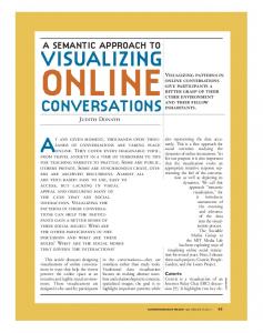
Fig. 5. Occlusion management visualized over time. As the camera moves forward, all objects that occlude a POI (red) are rendered as wire-frame.
This effect might distract the user and decreases the overall visual quality of the visualization. Rendering the occluder using a wire-frame style or similar can maintain the contextual information while minimizing the popping effects to a certain degree (Figure 5). However, it increases the visual complexity and the cognitive load for the user, especially if several wire-frame objects are visible and overlap each other. This effect depends mainly on the geometric complexity of the 3D models, i.e., the number of triangles of the corresponding mesh. The more triangles the object consists of, the more lines are generated. Thus, in a situation with a high number of consecutively aligned occluders rendered in wire-frame style, the high number of visible lines can lead to occlusion in turn. The increased cognitive load, recognizable in a scene with a large amount of wire-frame objects, occurs in techniques employing semi-transparency as well [10]. 6.2
Performance Evaluation
We have tested our approach using two virtual 3D city models of different geometrical complexity. All meshes are textured by one of 18 textures, e.g., grass, buildings. Moreover, one ambient light, depth testing, back-face culling, viewfrustum culling, and smooth shading are enabled (Figure 1, 4, 5). All results are summarized in Table 1. Our implementation is able to render the described scenes at interactive frame-rates. The energy consumption, which emerge from rendering the described scenes, is measured indirectly through battery charge state. Consequently, the respective results can be considered imprecise. Test 1 (T1) processes no OpenGL rendering at all, only the display is activated to measure a reference value for idle energy consumption. T2 renders a medium and large size model at the maximum frame-rate possible. As a result, the energy consumption roughly doubles, consequently the device runtime halves. T3 renders the same models with a limited frame-rate. As a result, the energy consumption decreases. This indicates a direct correlation between model complexity, rendering speed and the energy consumption.
12 Table 1. Results of our performance evaluation. T1 is a reference test for the relative energy consumption. T2 renders the scenes at maximum frame-rate. T3 renders with a limited frame-rate that reduces the energy consumption.
Test ID Model texture data meshes triangles avg. FPS rel. energy size in MB (avg. visible) (avg. visible) (* limited) consumption T1 T2 T3
-
-
-
Medium Large
4.1 8.2
624 (24%) 5924 (14%)
12380 34596
(35%)
Medium Large
4.1 8.2
624 (24%) 5924 (14%)
12380 34596
(35%)
(17%)
(17%)
-
1.0x
23 14
2.3x 2.2x
10* 10*
1.5x 1.8x
Our implementation implicitly makes the assumptions that the complete virtual 3D city model fit into device memory. However, the proposed prototypical implementation needs to be adapted to work for arbitrarily large models. In particular this concerns the 3D geometry and textures as well as the POI data. In this context, it is worth to evaluate possible advantages of using a POI service over out-of-core rendering and geometry streaming, which is a motivation to future studies.
6.3
Challenges for Future Work
Our main task for future work is to compensate visual clutter. The circle-based visualization can be improved by using stacks of circles to enable a visual separation for different POIs. In such case, different stacking schemes, which define what circle is above the other, are possible. We currently research priority-based and distance-based schemes. Further, we are striving to reduce the overlapping artifacts of the projection-based visualization by applying a 3D adaptation of the Wedge technique [1]. Based on the above extensions, we plan to conduct a comprehensive user evaluation. This would include the efficiency of our approach and a comparison of our 3D visualizations to alternative 2D off-screen location visualization techniques, such as Overview+Detail techniques. In the long term, we going to research possible strategies to overcome the memory limitations of mobile devices. Therefore, and in contrast to existing image-based approaches, we like to focus on the applicability of out-of-core visualization strategies, i.e., the streaming of textures as well as 3D geometry. Assuming a growing infrastructure, with respect to ubiquitous network access and increasing throughput, this seams a promising direction. The missing of appropriated rendering API features limits the image-quality of the presented approach, e.g., the occlusion management would profit from the
13
existence of a stencil buffer functionality. Most of the addressed drawbacks can be compensated using future versions of the OpenGL ES standard.
7
Conclusions
This paper presents a novel approach for visualization of POIs in 3D geovirtual environments on mobile devices. Our concept is based on the combination of a partially out-of frame technique and occlusion management. We further present an extended notion for characterizing POIs in 3D virtual environments, which enables their selection on a per-object basis at runtime. The provided performance evaluation considers the rendering performance and the power consumptions of our implementation.
Acknowledgments This work has been funded by the German Federal Ministry of Education and Research (BMBF) as part of the InnoProfile research group ”3D Geoinformation”’ (www.3dgi.de). We further like to thank Tassilo Glander for providing data sets of version of generalized 3D virtual city models. We gratefully thank the anonymous reviewers and Patrick Baudisch for their comments on this work.
References 1. Gustafson, S., Baudisch, P., Gutwin, C., Irani, P.: Wedge: Clutter-Free Visualization of Off-Screen Locations. CHI ’08: Proceeding of the twenty-sixth annual SIGCHI conference on Human factors in computing systems (Apr 2008) 2. Burigat, S., Chittaro, L., Gabrielli, S.: Visualizing Locations of Off-Screen Objects on Mobile Devices: A Comparative Evaluation of Three Approaches. MobileHCI ’06: Proceedings of the 8th conference on Human-computer interaction with mobile devices and services (Sep 2006) 3. Chittaro, L., Burigat, S.: 3D Location-pointing as a Navigation Aid in Virtual Environments. AVI ’04: Proceedings of the working conference on Advanced visual interfaces (May 2004) 4. Sarkar, M., Brown, M.: Graphical Fisheye Views. Communications of the ACM 37(12) (Dec 1994) 5. Hornbæ k, K., Frø kjær, E.: Reading of electronic documents: the usability of linear, fisheye, and overview+detail interfaces. In: CHI ’01: Proceedings of the SIGCHI conference on Human factors in computing systems, New York, NY, USA, ACM (2001) 293–300 6. Zellweger, P., Mackinlay, J., Good, L., Stefik, M., Baudisch, P.: City Lights: Contextual Views in Minimal Space. CHI ’03: CHI ’03 extended abstracts on Human factors in computing systems (Apr 2003) 7. Gustafson, S., Irani, P.: Comparing Visualizations for Tracking Off-Screen Moving Targets. CHI ’07: CHI ’07 extended abstracts on Human factors in computing systems (Apr 2007)
14 8. Baudisch, P., Rosenholtz, R.: Halo: a Technique for Visualizing Off-Screen Locations. CHI ’03: Proceedings of the SIGCHI conference on Human factors in computing systems (Apr 2003) 9. Marsh, T., Wright, P.: Using Cinematography Conventions to Inform Guidelines For the Design and Evaluation of Virtual Off-Screen Space. AAAI 2000 pring Symp. Ser. Smart Graphics (Jan 2000) 123–127 10. Elmqvist, N., Tsigas, P., INRIA, O.: A Taxonomy of 3D Occlusion Management for Visualization. Visualization and Computer Graphics (Jan 2008) 11. Chehimi, F., Coulton, P., Edwards, R.: Evolution of 3D Games on Mobile Phones. In: ICMB ’05: Proceedings of the International Conference on Mobile Business, Washington, DC, USA, IEEE Computer Society (2005) 173–179 12. Chittaro, L.: Visualizing Information on Mobile Devices. COMPUTER 39(3) (2006) 40–45 13. Nurminen, A.: A Platform for Mobile 3D Map Navigation Development. In: MobileHCI ’06: Proceedings of the 8th conference on Human-computer interaction with mobile devices and services, New York, NY, USA, ACM (2006) 101–104 14. Oulasvirta, A., Estlander, S., Nurminen, A.: Embodied interaction with a 3D versus 2D mobile map. Personal and Ubiquitous Computing (Jul 2008) 15. Moser, M., Weiskopf, D.: Interactive Volume Rendering on Mobile Devices. In: Workshop on Vision, Modelling, and Visualization VMV ’08. (2008) 217–226 16. Wells, M.J.: J2ME Game Programming (Game Development). Course Technology PTR (2004) 17. DiMarzio, J.: Android: A Programmer’s Guide. McGraw-Hill Osborne Media (2008) 18. Mark, D., LaMarche, J.: Beginning iPhone Development: Exploring the iPhone SDK. Apress (2008) 19. WWW: OpenGL ES. http://www.khronos.org/opengles/ Khronos Group [Online; accessed 12-Feb-2009]. 20. Board, O.A.R.: OpenGL(R) Reference Manual: The Official Reference Document to OpenGL, Version 1.2 (3rd Edition). Addison-Wesley Professional (1999) 21. Gamma, E., Helm, R., Johnson, R., Vlissides, J.M.: Design Patterns: Elements of Reusable Object-Oriented Software (Addison-Wesley Professional Computing Series). Addison-Wesley Professional (1994) 22. Glassner, A.S.: Graphics Gems I (Graphics Gems - IBM). Morgan Kaufmann (1990)