Dec 1, 2017 - of architecture-aware pruning, the two dominant techniques for obtaining resounce-efficient DNNs. We also describe local and global network ...
arXiv:1712.01084v1 [cs.LG] 1 Dec 2017
Structured Deep Neural Network Pruning via Matrix Pivoting Ranko Sredojevic1,2 , Shaoyi Cheng2 , Lazar Supic1 , Rawan Naous1 , Vladimir Stojanovic1 UC Berkeley 2 numericcal∗ {rrs,sh cheng,lazar,rawansn,vlada}@eecs.berkeley.edu 1
Abstract Deep Neural Networks (DNNs) are the key to the state-of-the-art machine vision, sensor fusion and audio/video signal processing. Unfortunately, their computation complexity and tight resource constraints on the Edge make them hard to leverage on mobile, embedded and IoT devices. Due to great diversity of Edge devices, DNN designers have to take into account the hardware platform and application requirements during network training. In this work we introduce pruning via matrix pivoting as a way to improve network pruning by compromising between the design flexibility of architecture-oblivious and performance efficiency of architecture-aware pruning, the two dominant techniques for obtaining resounce-efficient DNNs. We also describe local and global network optimization techniques for efficient implementation of the resulting pruned networks. In combination, the proposed pruning and implementation result in close to linear speed up with the reduction of network coefficients during pruning.
Keywords C.3.d Real-time and embedded systems, I.2.6.g Machine learning, I.5.1.d Neural nets, G.1.3.i Sparse, structured, and very large systems, I.3.1.a Graphics processors, D.3.4.g Optimization
1
Motivation
In order to build smart edge-based applications we must enable edge devices to leverage state-of-the-art algorithms for data processing and information extraction. Many of those algorithms are based on DNNs [1], [2]. The problem ∗ numericcal.com
1
of efficient implementation of DNN architectures on edge devices has received significant attention in recent literature [2]–[5]. However, the large number of different techniques reported indicates that there is no convergence and it is unlikely that a one-size-fits-all technique will be found. In fact, we will see examples showing that appropriate techniques depend on the application, the target hardware and the data set. Hence, we must navigate the trade-off between the network accuracy, size, energy and latency during hyperparameter tuning phase of network training. The best course of action in this situation is to discover, describe and characterize a large number of potentially useful techniques for navigating these trade-offs when designing DNNs for edge applications. Proposed solutions fall into three broad categories • Reduced-size network architectures [6], [7] impose size and structure constraints at the DNN level that are assumed to be appropriate for implementation on smaller devices. • Layer pruning techniques [2], [3] try to reduce the number of non-zero coefficients in layer weights, hoping for reduced number of operations as well as memory transfers. • Scalar tricks [8], [9] such as quantization or format conversion work by reducing the amount of storage or compute necessary for handling one scalar operation. This work introduces architecture-aware structured network pruning and implementation techniques optimized for low latency inference. Building on the previous work in architecture-aware pruning [2], [4], we introduce structured transformations that bridge the gap between allowing the flexibility in significant coefficient locations at the network layer level and structured groupings characteristic of most hardware architectures. These techniques allow us to achieve close to linear speed up, with reduction of layer coefficients, on modern embedded and mobile GPUs. Network training examples demonstrate marginal accuracy loss when imposing the proposed structural constraints during pruning. In latency optimization, fully-connected (FC) and late stage convolutional layers are the bottleneck. While it is widely acknowledged that majority of computation in modern DNNs happens in early convolutional layers [2], it is not widely understood that those layers are significantly easier to optimize through numerous opportunities for latency hiding and data reuse [10]. For example, in NVidia DriveNet running on Qualcomm Adreno 530 GPU early convolutional layers account for as much as ≈ 75% of all operations, but only ≈ 45% of inference latency. The last ≈ 3% of operations are responsible for ≈ 25% of the total DNN latency. Finally, while convolutional neural networks are widely used in literature for pruning studies, most networks (recurrent neural nets and multi-layer perceptrons) critical for day-to-day applications widely utilize the FC layers [11]. Hence, we will use the FC layers to demonstrate the proposed technique.
2
1.1
Contributions
The contributions of this work include: • Section 2 A novel technique to avoid gather-scatter problem when handling sparse matrix vector multiplication arising from pruning of FC layers. The technique relies on a representation of structured sparse matrices in what we call a permutation-block-permutation (PBP) form. • Section 3 Evidence that we can impose the PBP structure constraint in network training without significant negative impact on network accuracy. We show examples of PBP pruning of networks for MNIST, CIFAR10. The technique does not lose any accuracy on MNIST and stays within 0.5% of the original network performance on CIFAR10. • Section 4.1 An efficient strategy for single-layer (local) optimization of pruned FC layers by leveraging the PBP form. • Section 4.2 A set of compiler optimization techniques to leverage PBP form across multiple back-to-back FC layers. • Section 5 Experimental evidence that the proposed technique leads to significant improvement in inference execution speed when compared to the vendor-optimized dense and sparse linear algebra routines. Specifically, our approach leads to close to linear speedups with the reduction of matrix coefficients during pruning in all but fringe cases - small or highly sparse matrix, in which case it still outperforms other options.
2
Architectural insights
In general, pruning of DNNs will result in sparse layer matrices [3]. This allows programmers to leverage sparse matrix-vector multiplication when optimizing DNNs for inference. Unfortunately, generic sparse matrix libraries are tuned for fill-in levels below 1%, well below the fill-in of more than 5% we see in DNN pruning literature [2]–[5]. Hence, simply relying on generic sparse matrix-vector routines leaves significant performance on the table. We can observe this in recent works where speed increase due to sparsity lags significantly behind the reduction in coefficients [4], [5]. The reason for this inefficiency can be found if we observe the memory bandwidth utilization in dense and sparse matrix-vector multiplication. Typically, dense matrix-vector multiplication achieves excellent load and store bandwidth utilization. However, sparse matrix-vector multiply typically achieves good load bandwidth utilization, but very poor store utilization. Measurements of the load and store bandwidth utilization for different implementations can be found in Section 5.2. As a result, a variety of structured pruning [4], [5] techniques were proposed where full blocks, columns or rows of layer weight matrices are removed. These
3
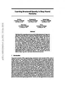
Figure 1: An example of (Msparse , Mblock ) pair techniques enables the use of dense linear algebra kernels despite the reduction in the size of layer weight matrices. However, this efficiency comes with a harsh constraint that we must remove a whole row/column if we want to remove a single element. In this work, we propose a novel structured transformations pruning approach that enables low latency implementation by constraining the sparse representation of pruned layers during computation while allowing for high flexibility of non-zero coefficient positioning in the network representation. The key idea is that network is pruned in such a way that there exists a convenient tensor transformation that turns the pruned network representation into a desirable computational structure. If we know this map at network implementation time we could account for it in our parallelization and vectorization strategies to achieve high runtime efficiency just like in structured pruning. At the same time, the tensor transformation should enable more flexible positioning of non-zero layer weights just like in unstructured pruning. One way to do this is to apply a standard technique from numerical linear algebra and high-performance real-time optimization [12]: compile-time matrix pivoting. Namely, for any fully connected layer matrix, we will perform the pruning to obtain Msparse that can be represented in what we call the PBP form Msparse = Prow Mblock Pcol (1) where Prow/col are row and column permutation matrices and Mblock is the computationally desirable matrix form tailored to a given underlying architecture. If such representation results in good network accuracy, we will have achieved our goal by encapsulating all computation and memory access irregularities into permutation actions. Furthermore, Prow/col will be static, i.e. these permutations depend on the sparsity pattern of the pruned matrix, only. Specifically, they do not depend on any runtime data. An example of (Msparse , Mblock ) pair of matrices is shown in Figure 1. As long as the overhead of the permutations is not larger than the savings due to structured computation, the approach should lead to speed-up. Once we have the PBP form of an FC layer, we can leverage associativity of matrix multiplication to isolate irregular memory access patterns in implemen-
4
tation as follows: aout = Msparse ain = (Prow Mblock Pcol )ain = Prow (Mblock (Pcol ain ))
(2)
In general, there is no reason to believe that such representation will be possible after unconstrained (proxy-based) pruning. Hence, we need to nudge the network to learn the sparse structure in such a way as to guarantee that the transformation in Eqn. 1 is possible.
3
PBP pruning
In the previous section we explained the intuition behind the PBP representation of pruned FC layers. Now we must evaluate the impact of imposing the PBP constraint on network accuracy. There are different ways to obtain PBP form during network training. We will describe two techniques and how they perform on TensorFlow tutorial examples for MNIST and CIFAR10 data sets. Coefficients for all example networks from this section, including the permutations needed for transitioning from Msparse to Mblock form, will be available online.
3.1
Feed-forward PBP pruning
A particularly simple way to obtain a PBP form of an FC layer is to just choose Prow/col before training and enforce it during training. This technique relies on coefficient redundancy in the network and, somewhat surprisingly, works quite well on some networks. When the resulting accuracy is acceptable, this approach is particularly convenient as it opens up a number of opportunities for cross-layer optimization, as we will see in Section 4.2. The baseline accuracy of TensorFlow Deep MNIST tutorial is 99.2%, which is achieved within 20,000 minibatch steps, with batch size B = 128. Picking two random permutations for rows and columns and setting the block structure for 6.125% and 50.0% fill-in on the fc1 and fc2, respectively, results in accuracy between 99.1% and 99.3%. It should be noted that picking identity permutations results in loss of accuracy over 10%. However, picking random permutation results in no accuracy loss with very high probability. We run hundreds of training sessions with randomly chosen permutations and have not seen any of them lose accuracy. As the second example, we use the TensorFlow CIFAR10 convolutional network tutorial. The baseline network accuracy, achieved within 125,000 minibatch steps, is (87.0 ± 0.1)%. The feed-forward approach to finding a PBP form with 12.5% fill-in, loses ≈ 1.6% accuracy. In such cases, to further optimize the trade-off between the fill-in and network accuracy we must search for more efficient ways to impose the PBP structure during network training.
5
3.2
Feed-back PBP pruning
An alternative to the feed-forward PBP pruning is the feed-back pruning, where we first train the network without pruning in order to determine where large, presumably more important, connections form in each layer [3]. We can use that information to pick permutations that would let us keep as many of such connections as possible. This problem is similar to graph bisection, and it cannot be solved exactly. Hence, we resort to a heuristic search. We start by training the network without any pruning. At this point, for each layer we intend to prune, we look at the absolute values of weights in the layer matrix and attempt to pick Prow/col that would maximize the sum of absolute values of coefficients in the upper left and the lower right sub-block of the layer matrix. This is done by greedy optimization starting from randomly chosen permutations. The coefficients that end up in the sub-blocks off the main diagonal are simply deleted and the training continues. Each time we repeat this process on a sub-block we delete 50% of coefficients in the block. In our tests we performed the bisection of all blocks (the number of blocks doubles after each bisection) three times on local3 and two times on local4 layers of the TensorFlow CIFAR10 tutorial network, resulting in 12.5% and 25.0% fillin factors. After 200,000 minibatch steps (not including the original training) the network converges to 86.7% accuracy. Figure 1 shows the resulting local4 layer matrix in both the sparse and blocked form.
4
Implementation
In the previous two sections, we explained the intuition behind the PBP form and demonstrated a few possible ways to obtain a network that satisfies such a constraint. In this section we return to Equation 2 and describe in detail a high-performance implementation for mobile class GPUs. We will handle local (single-layer) and global (multi-layer) optimization separately.
4.1
Single-layer optimization
Given the different computational nature of permutation and block-matrix/vector multiplication we will handle them separately. 4.1.1
Block-matrix multiplication
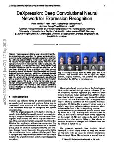
Let us consider a sparse block-matrix shown in Figure 2a. We assume that each colored block is potentially a dense submatrix, while the white areas represent zero coefficients. For now, we assume that blocks are identical squares that occupy non-overlapping sets of rows. We will comment on handling of different block and matrix shapes in Section 4.1.5. We order the blocks arbitrarily, for example in purple-blue-green-orange order, as we map them to physical memory of the GPU.
6
(a) Logical view
(b) Physical layouts
(c) Access pattern
Figure 2: Different logical to physical memory mapping of Mblock With Figure 2a in mind, our goal is to efficiently implement the Mblock multiplication from Equation 2. We approach the GPU implementation with the following model in mind: • We will launch one thread group per block. • Within a thread group will have one thread per output coordinate, i.e. each number in the output (activation) vector will be calculated by one thread working along the row of a block (sub-matrix). With these guidelines in mind, it is simple to implement efficient GPU thread kernels (e.g. OpenCL, CUDA, Vulkan). As usual, a number of implementation tricks like loop-unrolling and scalar promotion [10] are useful in tuning performance. The biggest improvement, however, comes from aligning and coalescing memory accesses. To optimize memory access we consider three different memory layouts, shown in Figure 2b. Later, in the Section 4 we will see that the correct choice of the memory layout depends on the target computer architecture. Interestingly, most results to date typically argue for one specific memory layout overlooking the strong interaction between the computer architecture and performance optimization. Capturing this strong interaction effectively is the biggest challenge in bringing high-quality, easy-to-use DNN technology to the heterogeneous hardware platforms on the Edge. In the image we represent memory as an array of cells with consecutive addresses moving left-to-right/top-to-bottom. We name the layouts after the tensor axis layout order using rightmost axis changing fastest rule. We indicate the correspondence between the logical layout in Figure 2a and physical layouts in Figure 2b using color shades: 1. Block-Row-Column (BRC) layout, or row-major within block, fixes the block and lays out each block row consecutively in memory. Hence, column coordinate within each row changes with each consecutive memory location. 2. Block-Column-Row (BCR) layout, or column-major within block, fixes the block and lays out each block column consecutively in memory. 7
3. Column-Block-Row (CBR) layout tries to maximize memory coalescing by fixing the column and then laying out that column position from all blocks consecutively in memory. Finally, Figure 2c demonstrates the memory reads across all threads on the first computation cycle after launching a set of thread groups. We should keep in mind that we parallelize on output, with each thread handling one output activation coordinate. Hence, the first column of each block will be fetched first after launching the grid. As expected, the preferred memory layout depends on the architectural features of the underlying GPU device. We now briefly review architectural features of different device families to understand access pattern influence on performance. 4.1.2
Implementation tradeoffs on NVidia Maxwell GPU
NVidia GPUs (and similar devices) use Single-Instruction-Multiple-Threads (SIMT) model. Threads are grouped into warps and warps into blocks. While each thread has its own state, including the Program Counter, maximum device utilization is achieved if all threads within a warp execute the same instruction on the same cycle. Furthermore, we aim to align memory accesses across threads in a group to minimize the number of bus transactions needed to fetch and store data. Typically, at the start of kernel execution all data is in the global GPU memory, uploaded by the host system. In this case all the blocks are in global memory regardless of the layout scheme. In our experiments, due to low compute per fetch in FC layer processing, prefetching from global memory through combined efforts of the thread group was not effective or needed. The latency of global memory fetch can be hidden well most of the time through instruction level parallelism within a scalar thread. There are a number of independent operations to be performed within each thread, essentially implementing a dot product between the assigned block row and a subsection of the vector being multiplied. We also aid the GPU compiler by summing consecutive fetches to multiple partial register accumulators and reducing them at the end of thread’s execution. In this situation where all warp threads share memory bandwidth and run in lockstep the preferred memory layout is CBR as it provides the best memory coalescing. As we will see in Section 5 this is confirmed in our experiments. In practice, the BCR comes close second. When the amount of data fetched is extremely small, e.g. small matrices with low fill-in, BCR is a little slower as it wastes bandwidth by forcing multiple fetches due to gaps in memory accessed on the same cycle, Figure 2c. However, for higher fill-in levels there is sufficient data in every strip of memory in Figure 2c for BCR to effectively use the memory bandwidth and this difference disappears. BRC layout, Figure 2b, uses memory bandwidth very inefficiently, Figure 2c, and that shows both in load efficiency and in computation latency measurements.
8
4.1.3
Implementation tradeoffs on ARM Mali GPU
The ARM Mali GPU, in particular the Midgard architecture, has a different parallelization model than Nvidia devices. Even though it is also a massively multithreaded computation platform, where large number of threads are needed to keep the device busy and hide memory access latency, it does not use the SIMT paradigm. Instead of bundling multiple threads together and pushing them through the array of ALUs, Mali executes each thread independently. Meanwhile, cross-thread memory coalescing, an important factor in achieving good performance in Nvidia devices, does not result in better speed here. BRC layout, whose performance lags both BCR and CBR layout when Nvidia GPU is used, achieves the fastest speed in Mali. With BRC, every individual thread (instead a warp of threads) fetches a contiguous chunk of data, which is more compatible with Mali’s execution model. Section 5 will present the achieved performance of this layout. 4.1.4
Handling permutations
In Section 2 we described our plan to isolate all memory access irregularities into a separate processing step. This allowed us to pack Mblock into a set of dense blocks and produce an efficient implementation described in the previous section. Now we must handle the irregular computation pattern, encapsulated in the row/column permutation matrices. Unfortunately, there is no invariant or reasonable assumption we can introduce around permutations. We currently do not have a way to impose constraints on permutations during PBP pruning (network training) without sacrificing too much accuracy. Hence, we must handle Prow and Pcolumn in a completely general way. We represent permutations in global GPU memory as index arrays. For example, the index array of ”cab” relative to ”abc” is [2, 0, 1]. Incoming vector, produced by the previous network layer, is also assumed to be stored in the global GPU memory. Looking at Figure 2a we observe that each block only acts on a sub-slice of the incoming vector vin , as all weights that share row but not column coordinates with a particular block are zero. Hence, each block only needs access to a subset of the input vector coordinates. Moreover, this subset is shared across the block, meaning that it can be pre-fetched in parallel by all threads in the tread group working together. Similarly, each block only produces a subset of the outgoing vector vout coordinates. As explained previously, each thread in a thread block will process one row of the block-matrix. Hence, we could store values produced by the block in thread group (shared) memory and update the global memory after all threads finish. Pseudo-code for an implementation of a GPU kernel along these lines is
9
shown in Listing 1. Listing 1: PBP kernel with separate row/column permutation input : activation vector ain , matrix Mblock , index arrays Prow /Pcol output: output activation vector aout 1 identify the thread’s global coordinate (Block, Row); 2 identify the BlockColumns set; 3 identify the BlockRows set; 4 group fetch alocal [] ← ain [Pcol [BlockColumns]]; 5 synchronize threads(); 6 for c ← 0 to BlockColumns do 7 acc[Row] ← acc[Row] + Mblock [Block][Row][c]alocal [c]; 8 9
synchronize threads(); group store acc[] → aout [Prow [BlockRows]]
Starting from this baseline implementation we will proceed to handle more general cases and optimize performance. 4.1.5
Irregular matrix shapes
In the previous section we assumed that all blocks have the same size and that no two blocks share any of their row coordinates within the block. It is simple to extend the described technique to a more general setting. It is easy to see that blocks can have different sizes if we pass information about block sizing to the kernel and use the Block coordinate in Listing 1 to lookup the block the current thread is processing. If any two blocks share row coordinates we can have an additional reduction step after each block is processed as described previously.
4.2
Cross-layer optimization
Though Listing 1 can handle general permutations, they introduce overhead, as reported in Section 5.1.1. First, we are forced to perform the input fetch into alocal that is not necessarily coalesced since there is no constraint on Pcol . Then we must synchronize threads after the group fetch. Similarly, we must synchronize before storing all the accumulators from a thread group according to Prow which, again, does not guarantee a coalesced store. Luckily, we can simplify and optimize the implementation by leveraging the algebraic properties of permutations and their interaction with domain specific operators. To do this we must consider cross-layer interactions. First, we can remove the need for the Prow in most situations. 4.2.1
Cross-layer permutation fusion
Consider two consecutive PBP fully connected layers, represented with pruned matrices Asparse and Bsparse . They would, typically, be connected through a non-linear, point-wise operator such as reLU. To see how we can leverage this situation we need two simple facts.
10
Observation 1 Permutations commute with point-wise operators such as reLU. In other words, whether we first permute a vector and then apply a function to each element of the resulting vector has the same outcome as first applying the function and then permuting the result. Furthermore, permutations commute with softmax and similar operators. Observation 2 The product of two permutation matrices, i.e. the composition of two permutations, is again a permutation. With this in mind we return to our case of back-to-back PBP FC layers. We can represent this situation with the following pipeline section · ← Asparse ← reLU ← Bsparse ← · A A A B B B · ← Prow Mblock Pcol ← reLU ← Prow Mblock Pcol ←·
·← ·←
A A A B B B Prow Mblock (Pcol Prow ) ← reLU ← Mblock Pcol ← A A AB B B Prow Mblock Pcol/row ← reLU ← Mblock Pcol ← ·
using Equation 1 · using Observation 1 using Observation 2
In other words, the row permutation Prow implemented in lines 8 and 9 in Listing 1 can be moved into the next layer and fused into the colum permutation Pcol implemented in lines 4 and 5. Furthermore, since PBP form relies on statAB ically known permutations, the product Pcol/row can be determined at network implementation time, by an optimizing domain specific compiler. Hence, we do not need to handle the output permutation whenever two PBP sparse layers are back-to-back in a DNN, which allows us to remove the processing in lines 8 and 9 in such cases. 4.2.2
Output permutation elimination
In classification tasks we can use a similar optimization at the output of the network. For example, extending the previous example with an output softmax we can write A A AB ← sof tM ax ← Prow Mblock Pcol/row ←· A A AB Prow ← sof tM ax ← Mblock Pcol/row ←·
using Observation 1
A At this point we can simply drop the final permutation Prow since it simply relabels the coordinates of the output vector. The host application can take it into account when interpreting the result.
4.2.3
Cross-layer permutation elimination
Finally, in some situations we can completely eliminate all inference-time (runtime) overhead of permutations between two PBP layers. To do this, we must AB check whether the PBP training can be adjusted to force Pcol/row = I. In other A T B words, we need to train the network in such a way to have (Pcol ) = Prow . 11
5
Results
To test the effectiveness of the proposed approach we have implemented the kernel described in Listing 1 with the cross-layer permutation fusion described in Section 4.2.1. All results are measured for square matrices with square, identically sized blocks. For example, the case for size = 512 and f ill−in = 6.25 was measured with 512 × 512 matrix with 16 identical 32 × 32 blocks.
5.1
Execution speed
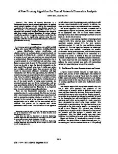
The execution latency as a function of the matrix size and fill-in level on NVidia Jetson TX1 SoC with Maxwell class GPU is given in Figure 3. Results compare implementations with the three memory layouts, CBR, BRC and BCR, against the NVidia cuSPARSE library, a generic sparse linear algebra library typically used to implement pruned FC layers. The measurements support the analysis in Section 4.1. Speedup of the proposed method with CBR layout, defined as the ratio between the latency of generic dense (cuBLAS) and sparse (cuSPARSE) matrixvector multiplication to the latency of the proposed implementation, on NVidia Jetson TX1 is given in Table 1a. On Mali GPU, speedup with BRC layout over the OpenCL dense matrix-vector multiplication in ARM Compute Library is given in Table 1b. It is worth noting that this result for Mali T880 showed a great amount of variability. This is likely due to the fact that we have used an actual cellphone for the experiment. Features ensuring pleasant user experience and prolonging battery life, e.g. aggressive thermal throttling and dynamic voltage frequency scaling, all affect the final measurements in non-deterministic ways. 5.1.1
Permutation overhead
The overhead of performing permutation, as shown in lines 4 and 5 of Listing 1 is negligible for large blocks and high fill-in factors. However, when fill-in factor is below 12.5% and the block is smaller than roughly 128 × 128 on NVidia TX1, the time to perform one permutation is ≈ 50% of the kernel run time. The high overhead of permutation for small matrices and low fill-in factors is noticeable in Table 1a. Specifically, bold numbers emphasize the cases where our implementation achieves linear and better than linear speedup with the reduction of matrix coefficients. It is obvious that there are no bold numbers along the edges and in the upper left corner of the table, exactly where the measured permutation overhead was high. Most importantly, for fill-in factors of 6.25% - 12.5% and sizes larger than 128-256, which are typical values for the sparsest FC layers, permutation overhead is negligible.
12
Figure 3: Average compute latency over 2,500 calls on Jetson TX1
5.2
Resource utilization
In Section 2 we conjectured that performance of a sparse matrix-vector multiplication can be improved by constraining and encapsulating irregular memory access patterns in permutation operators. We measured resource utilization on NVidia Jetson TX1 hardware using NVidia profiler, nvprof. Table 2 shows that PBP form, with Section 4.2.1 optimizations, achieves load and store efficiency on par with dense matrix multiply, significantly outperforming generic sparse matrix-vector multiplication.
6
Conclusion
Deep Learning has the potential to become widely utilized in many applications on the Edge. However, for widespread use of DNNs in embedded and mobile software to take place, we must ensure that design, optimization, integration and management of DNNs alongside the standard business logic is straightforward and efficient. As a community we have a long way to go before we reach the moment when application developers will not think twice before reaching for a DNN to solve their problem or improve a feature of their software. In this work we developed structured sparsity under transformation for the Edge Machine Learning toolbox. We demonstrated how static matrix pivoting can be used to induce computationally friendly PBP structure in sparse DNN layers and demonstrated architecture-specific optimization of PBP layers. 13
fill-in size 64 128 256 512 1024 2048 4096 speedup vs
3.125% 2.00 6.83 22.61 13.02 26.02 26.72 34.40 cuBL
6.25%
0.86 1.73 2.71 4.29 4.70 2.47 2.49 cuSP
2.37 7.44 28.35 16.37 17.56 15.12 17.65 cuBL
12.5%
1.22 2.36 4.22 7.00 4.02 2.79 2.79 cuSP
4.13 7.87 22.55 12.19 7.58 8.10 8.82 cuBL
1.56 4.14 3.80 6.48 3.09 2.84 2.44 cuSP
25.0% 3.36 5.86 16.15 4.98 4.01 4.10 4.46 cuBL
2.04 2.79 3.55 3.53 2.83 2.57 2.36 cuSP
(a) Speedup of PBP vs cuBLAS/cuSPARSE on Jetson TX1
fill-in size 64 128 256 512 1024 2048 4096
3.125%
6.25%
12.5%
25.0%
3.90 5.71 9.02 10.92 9.69 7.67 14.09
3.64 5.44 8.89 7.81 5.33 5.81 9.26
3.51 4.74 7.04 4.93 2.36 3.15 6.97
2.98 4.28 4.68 2.24 2.09 2.30 3.85
(b) Arm Mali T880 on Huawei Honor 8
Table 1: Speedup of the PBP gemv() over vendor libraries Going forward we expect that the next generation of DNN frameworks will appear, specifically optimized for Edge deployment. Unlike the current solutions, the new generation will need to be organized as domain specific compilers, not simple interpreters. Such transition will enable the use of domainspecific cross-layer optimization opportunities and fine-grained architecturespecific DNN tuning like the ones described in this paper. The outcome will be more efficient and productive DNN design iteration enabling faster innovation and deployment on the Edge.
References [1]
Y. Lecun, Y. Bengio, and G. Hinton, “Deep learning,” Nature, vol. 521, no. 7553, pp. 436–444, May 2015, issn: 0028-0836. doi: 10.1038/nature14539.
14
metric kernel gemv2N csrMv brc bcr cbr
gld efficiency
gst efficiency
occupancy
100.0 99.32 12.52 98.1 98.7
100.0 12.5 100.0 100.0 100.0
54 97 52 42 41
Table 2: GPU resource utilization % as reported by NVidia nvprof on gemv() [2]
T.-J. Yang, Y.-H. Chen, and V. Sze. (2016). Designing energy-efficient convolutional neural networks using energy-aware pruning. arXiv: 1611. 05128.
[3]
S. Han, J. Pool, J. Tran, and W. J. Dally. (2015). Learning both weights and connections for efficient neural networks. arXiv: 1506.02626.
[4]
J. Yu, A. Lukefahr, D. Palframan, G. Dasika, R. Das, and S. Mahlke, “Scalpel: Customizing dnn pruning to the underlying hardware parallelism,” in Proceedings of the 44th Annual International Symposium on Computer Architecture, ser. ISCA ’17, Toronto, ON, Canada: ACM, 2017, pp. 548–560, isbn: 978-1-4503-4892-8. doi: 10.1145/3079856.3080215. [Online]. Available: http://doi.acm.org/10.1145/3079856.3080215.
[5]
S. Anwar, K. Hwang, and W. Sung. (2015). Structured pruning of deep convolutional neural networks. arXiv: 1512.08571.
[6]
A. G. Howard, M. Zhu, B. Chen, D. Kalenichenko, W. Wang, T. Weyand, M. Andreetto, and H. Adam. (2017). Mobilenets: Efficient convolutional neural networks for mobile vision applications. arXiv: 1704.04861.
[7]
F. N. Iandola, S. Han, M. W. Moskewicz, K. Ashraf, W. J. Dally, and K. Keutzer. (2016). Squeezenet: Alexnet-level accuracy with 50x fewer parameters and ¡0.5mb model size. arXiv: 1602.07360.
[8]
M. Rastegari, V. Ordonez, J. Redmon, and A. Farhadi. (2016). Xnor-net: Imagenet classification using binary convolutional neural networks. arXiv: 1603.05279.
[9]
I. Hubara, M. Courbariaux, D. Soudry, R. El-Yaniv, and Y. Bengio. (2016). Quantized neural networks: Training neural networks with low precision weights and activations. arXiv: 1609.07061.
[10]
D. Loshin, Efficient memory programming, 1st. McGraw-Hill Professional, 1998, isbn: 0070388687.
[11]
N. P. Jouppi, C. Young, N. Patil, et al. (2017). In-datacenter performance analysis of a tensor processing unit. arXiv: 1704.04760.
15
[12]
J. Mattingley and S. Boyd, “CVXGEN: A code generator for embedded convex optimization,” Optimization and Engineering, vol. 12, no. 1, pp. 1– 27, 2012.
16