and testing of the flight software of ICUBE-1 which is a premier. CubeSat of any institution in Pakistan. ICUBE-1 is scheduled to launch in 2nd quarter of 2013.
Subsystem Testing, Integration and Compliance of ICUBE-1 Rehan Mahmood, Khurram Khurshid, Qamar ul Isalm Department of Electrical Engineering Institute of Space Technology Islamabad, Pakistan {rehan, khurram.khurshid, qamar.islam}@ist.edu.pk the institutions and universities to rapidly develop the CubeSats without the hassle of designing the LVI.
Abstract—This paper describe the design, implementation and testing of the flight software of ICUBE-1 which is a premier CubeSat of any institution in Pakistan. ICUBE-1 is scheduled to launch in 2nd quarter of 2013. The ICUBE-1 fight software is developed to fulfill the main mission requirements, most important of which is to successfully establish the communication link with ICUBE-1 after launch and to receive the ICUBE-1 health data. This paper also describes the software architecture and design techniques used in the development of the flight software of ICUBE-1. Because of the usage of different Commercial off the Shelf (COTS) components in ICIBE-1, the software design & development team has not much liberty to use different software engineering principals. However, the ICUBE-1 has introduced the redundancy by design and other techniques to ensure the reliability of the software in-orbit. The paper also discusses the testing of the flight software while assuring the functioning as per the requirements.
The idea of CubeSat development is also welcomed by the several space organizations and they started developing these pico-satellites as their testing platform to qualify certain components without huge investment and to perform low cost demonstration missions [3]. II.
ICUBE is the small satellite development program of the Institute of Space Technology (IST), Pakistan. Being an institute of space technology, IST started this program with a vision to include the flavor of practical satellite development process in its curriculum. The program was started with a motivation to produce engineers with hands-on experience of satellite development process so that they can better participate in the space industry. In future, IST has also planned to involve other institutions and universities of Pakistan as well as abroad in this program to develop the ICUBE-2, which would be the 2nd satellite of this program.
Keywords—ICUBE-1; CubeSat; Computer Software; PicoSatellite; Flight Software
I.
INTRODUCTION
CubeSat became a de-facto standard for the development of small usually educational satellites proposed by Stanford’s Space System Development Laboratory (SSDL) and California Polytechnic State University’s Multidisciplinary Space Technology Laboratory (MSTL) in 1999[1]. Initially, the standard is defined for one unit (1U) CubeSat weighing less than 1kg and having dimension of 113.5mm x 100mm x 100mm. Later, the mass of the 1U CubeSat was revised to 1.33 kg however; the initial dimensions were retained to facilitate the use of a standard Launch Vehicle Interface (LVI). The larger CubeSats are also possible as per the defined specifications [1], called as 2U and 3U CubeSats with dimensions of 213.5mm x 100mm x 100mm and 313.5mm x 100mm x 100mm respectively.
A. ICUBE-1 CubeSat ICUBE-1 is the first satellite of the ICUBE program. The project was conceived in late 2009 when it was decided to develop a 1U CubeSat by involving students as well as faculty from different disciplines. Being the premier CubeSat of any institution and university in Pakistan, the faculty and students have no prior experience of satellite development. Added to that, IST has not enough facilities which are generally required in the spacecraft development and testing process. However, after the conception of this project, ICUBE team has started developing some in-house facilities to ease the initial designing and development. It includes the development of a clean environmental chamber of class 1,000, VHF/UHF/S Band ground station to communicate with the amateur satellites and other supporting tools and equipment generally used in the development of the different subsystems. The decision of using the Commercial-Off-The-Shelf (COTS) components makes it convenient for the team to procure these components. However, ICUBE team has preferred to use the components in different subsystems which have some flight heritage.
Since the evolution of the CubeSat specifications, several universities have started developing CubeSats and at the time of writing this paper, more than 100 universities have developed the CubeSats and most of them were launched into their desired orbits. The idea of the small satellite development, particularly of CubeSat was also adopted by several institutions mainly because of the availability of a common LVI usually called as Poly Pico-satellite Orbital Deployer (PPOD) [2] developed by California Polytechnic University. The idea of using a similar deployer to deploy small satellites encourages
978-1-4673-6396-9/13/$31.00 ©2013 IEEE
ICUBE
881
simplicity, the attitude of the ICUBE-1 is controlled passively by the use of a permanent magnet and two hysteresis rods. The image acquisition board also contains the interface for the Antenna Deployment System (ADS) which provides the power, data and RF lines to the ADS. IV.
ICUBE-1 includes several subsystems and components which include Electrical Power System (EPS), Communication Subsystem (COMM), On-Board Computer (OBC), Passive Attitude Control System (PACS), Antenna Deployment System (ADS), Imaging Camera, Inertial Measurement Unit (IMU) and solar cells. After the development of several subsystems and the integration of some modules at lower level, it has been decided as per the plan to test each subsystem individually or in some cases with the OBC as most of the times, different subsystems and components are communicating with OBC and of course with the help of EPS.
Fig. 1. Subsystems of ICUBE-1
ICUBE-1 will be launched in the 2nd quarter of 2013 via Dnepr launch vehicle from the Yasny launch base in Russia. The orbit will be 600km polar orbit with an inclination of 98o. ICUBE-1 will be launched as a piggyback inside UniSat-5 which will deploy the ICUBE-1 in the orbit after its stabilization. Figure 1 shows different integrated subsystems of ICUBE-1. III.
SUBSYSTEM TESTING
The test team, which is a part of the subsystem development team, decided to develop software test benches which can run on a PC so that the testing of any subsystem or component can easily be monitored and logged. Also, in some case, the software test benches can provide the flexibility to deliberately put the subsystem in situation not possible with only hardware solutions. In the section below, the subsystems and components testing of ICUBE-1 is briefly summarized.
MISSION REQUIRMENTS
Being the first CubeSat of ICUBE satellite development program, ICUBE-1 has very simple mission requirements. The primary goal of the involved faculty and the students is to design, develop, test and launch the ICUBE-1 as per the space standards. The extended objectives include the execution of the uplink commands and the reception of response by ICUBE-1. Another extended objective is to receive the images from onboard camera.
A. Electrical Power System (EPS) Testing The EPS used in the ICUBE-1 is supplied by the ClydeSpace Inc, UK. The module has the flight history and used in some CubeSats. EPS has three BCR’s which can be directly connected to the Triple-Junction Solar Cells. It provides three power lines, +3.3V, +5V and raw voltage from the batteries. The two batteries are connected in series with a capacity of 10Whr. ICUBE-1 team decided to put another 10WHr battery in EPS to increase the overall capacity. The battery provides its health information and also accepts commands to refresh power lines over I2C bus. For testing purpose, hardware was developed with the PC/104 connector, Remove Before Flight (RBF) and Deployment Switches. A SUB20 adapter is used to interface the I2C bus of the EPS to the USB of the computer. The software test bench developed not only issues the command over the I2C bus also read the different parameters of EPS. It also controls the load attached to the power lines of the EPS via GPIO lines available on the SUB20 adapter. The solar panels were simulated using a computer controlled power supply. The testing process was run for several days and during that period, the data, behavior and the output of the EPS was logged as per the plan. The EPS was put in different loading situations using the written scripts. The testing team has inspected each and every aspect of the EPS from the design and requirements point of view.
Initially, ICUBE-1 mission seem little difficult for the untrained undergraduate students as it is very time consuming and difficult to develop the bus subsystems of ICUBE-1 from scratch. Therefore, it was decided to conduct different studies related to the subsystems development by dividing the students in different groups. These theoretical studies became the basis of the development and fabrications of different subsystems. However, some of the COTS subsystems were used in ICUBE1 which were customized on the basis of the studies conducted by the students. The reason to use this approach is to rapidly involve the students in the design and development process. Although, some subsystems of ICUBE-1 were customized and procured Off-the-Shelf but the payload of ICUBE-1, which is an image acquisition board is completely designed and developed by the students. The image acquisition board contains a CMOS imaging camera for taking images, compress them and to store them on the on-board SD card. An Inertial Measurement Unit (IMU) is also added to the custom designed image acquisition board which will be used to collect the attitude data of the ICUBE-1. It contains 3-axis accelerometers, 3-axis gyroscopes, 3-axis magnetometers and a temperature sensor. The IMU is not a part of the attitude control unit of ICUBE-1 as for
B. Communication Subsystem (COMM) The transceiver of the ICUBE-1 is provided by the ISIS, Netherlands [5]. It is a modified version of one which was
882
used in Delfi-C3 launched by TuDelft, Netherlands. The UHF amateur band is used for uplink while the VHF amateur band is used for downlink. The uplink is on 1200bps AFSK and the downlink is on 1200bps BPSK. The transceiver can also be put in the CW or AX25 beacon mode.
E. Inertial Measurement Unit (IMU) testing Although, ICUBE-1 is using a Passive attitude control mechanism, the team decided to put an IMU to gather the information about the orientation of the ICUBE-1 during the life time of the mission. The attitude data will be stored in the SD card of OBC and later, it will be downloaded via uplink commands. The data will be stored with seconds resolution however; the resolution of the storage data can be updated via command from the ground station. The IMU is provided by Analog Device. It is of ADIS 16400 series and has 3-axis accelerometers, 3-axis gyroscopes, 3-axis magnetometers and a temperature sensor. The IMU was pre-calibrated but to increase the confidence and to verify the outputs, ICUBE-1 team has decided to test the IMU on a 3-axis platform. The IMU provides the information in digitized format. Registers are also available to add offset to the output of any register. To mount the IMU on the 3-axis platform, a physical interface was designed to mount the IMU over the platform. The interface has also connections to electrically connect the power and data lines with the slip rings of the 3-axis platform. The data lines are interfaced with a computer and the commands were issued to read the data using Labview. The software has also the capability to log all the data. The test was started by tilting the 3-axis platform on various degrees and the output of the accelerometers was automatically logged in the software. Same process was repeated for the other axis of accelerometers. In the next step, the 3-axis was spun at different rotational speed and the output of all the gyroscopes at different axis was logged. The 3-axis magnetometers were also calibrated using the Helmholtz coil. The data logged was later used to remove any calibration errors and offsets in the IMU.
For testing of COMM, two dipole antennas were developed which were impedance matched to the transceiver. Initially, the transceiver was connected directly to the ground station transceiver using attenuators and all the commands were tested over the I2C bus using the PC based Software. Later, for field testing, the test team took the transceiver away from the ground station with an aerial distance of more than 26kms. Transceiver passed all the tests as per the test plan. C. Antenna Deployment System (ADS)Testing In the ADS of ICUBE-1, two antennas are used to maintain a communication link of ICUBE-1 with the ground station. The antennas are dipoles which re stowed and held in a position using dyneema threads in ADS. Upon activation via I2C bus, heating element burns the dyneema thread and the antenna will be released because of its tension. A released switch after deployment verifies the status of antenna. For testing purposes, the ADS was interfaced with the computer and I2C commands were issued to deploy the antennas in a sequential manner. D. Magnetic stabilization System ICUBE-1 is the premier satellite of IST and thus to keep the design simple, ICUBE-1 has decided to avoid the 3-axis attitude control systems. Instead, ICUBE-1 has a passive attitude control system which consists of a permanent magnet and two hysteresis rods. The permanent magnetic will align the ICUBE-1 with the Earth’s magnetic lines of forces and two hysteresis attached orthogonal to the permanent magnet will try to oppose the rotation of ICUBE-1 around the permanent magnet axis. The passive attitude control system was tested in the Helmohltz coil with a camera on top of the Halmohtz coil assembly to observe any movement of magnet and the hysteresis rods and the data was also recorded for later analysis. Initially, the magnet was suspended with the help of a thread. The thread was chosen carefully to avoid any twist because of the tension of the thread. The magnetic field then varied and the orientation of the magnet was observed in response to the magnitude of the magnetic field.
F. Integration and overall testing During integration, ICUBE-1 has used all the standard procedures. It includes the use of proper fasteners and space grade epoxies with low outgassing properties. The overall ICUBE-1 satellite functionality test was started after the integration of ICUBE-1.
In the next step, the hysteresis rods were also mounted along with the permanent magnet to observe of the effect of hysteresis rods were observed in response to the varying magnetic field. As the magnetic field changes, notable difference was observed in the rotation rate of the magnet and the hysteresis rods. The same process was repeated for different axis with varying magnetic field. All the activity was recorded for later analysis. The recorded data was later handed over to several other groups for analysis to better understand the response of the magnetic attitude control system in different circumstances.
Fig. 2. ICUBE-1 during integration using stainless steel threaded pillars
883
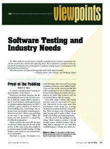
The testing includes the combined testing of all the subsystems which includes the flight software of the IUCBE-1 as shown in figure 3. The integration of ICUBE-1 was based on the integration document developed over time and was simulated several times on the 3D CAD software, SolidWorks. According to the integration scheme, different subsystems were stacked over one another via PCI-104 connectors using threaded stainless steel pillars as shown in figure 2. The lengths of some of the connectors were altered as per the plan to accommodate all the subsystems. The stainless steel spacers were used in between different subsystems to accommodate the load properly. The length of the spacers was altered using laser cutting to avoid any deformation of the spacers. All the fasteners were locked using 3M Scotchweld 2216 epoxy. The harnesses were routed in such a way to avoid any accidental damage during or before launch.
Fig. 4. ICUBE-1 structure showing the cavity for solar panel connectors
ICUBE-1 Workstation
Data logging, I2C, SPI, UART
Ground Station
Satellite to Computer interface
Command Uplink Script
Downlink Data logging and storage
Power Supply to Simulate Solar Cells
After the testing of the individual modules, the code was integrated as per the requirement and the fully integrated code was put in the testing process. To test the communication via different interfaces of the microcontroller, specialized hardware developed which is permanently attached to the OBC interface lines which monitors and log the electrical activity over SPI, I2C and UART. The logged data is interpreted and observed to find any errors. This data was very helpful to observe the sequence of data travel and usage of the different interfaces. To provide the realistic power availability, a desktop power supply was developed which is interfaced to a computer. A script controls the available voltage and power to put the satellite in a position similar to the real orbital environment in terms of power availability.
Fig. 3. ICUBE-1 test setup after integration
Besides these activities, the ground station transceivers were connected to the ICUBE-1. Test bench software written to execute the uplink commands as per the schedule. The software also receives the response of the ICUBE-1 such as the image or the health data and save them in a database. This hardware in loop testing helped to remove several bugs in the flight software and also results in the smooth functioning of the flight software autonomously.
The ICUBE-1 structure is a 1U solid walled structure made from space grade aluminum 5052-H32. In order to accommodate the power and telemetry connectors of the body mounted solar panels, a small cavity was created in the walls of the ICUBE-1structure using laser as conventional techniques may result in the deformation of the structure. This is shown in figure 4. The solar panels were held in place via solar panel clips fixed rigidly under the feet of the structure. The thermal conductive epoxy STYCAST 4952 was also used to enhance the bonding between the panels and structure and also to promote heat transfer between them.
V.
ICUBE-1 COMPLIANCE
The compliance of ICUBE-1 was based on the two important tests which includes the Thermal Vacuum Test (TVT) and the Vibration test (VT). The TVT is to ensure that no such material with higher outgassing rate as specified by NASA was used in the ICUBE-1. This test is mainly to ensure that the any outgassing from ICUBE-1 will not affect the lunch vehicle or another spacecraft of the cluster launch. Further, the lower outgassing rate offers less probability of contamination of different components and subsystem within the spacecraft. In ICUBE-1, the most important of which are solar cells and the camera lens. The contamination of one of these will degrade performance and hence reduces the probability of a successful mission. The second important compliance test is the VT which is mainly to ensure the
Testing process of the ICUBE-1 was very formal and well documented. Figure …shows the testing process of the ICUBE-1. The testing process of the flight software was continued for more than 6 months and the satellite was powered on continuously for this period. Initially, all the modules were individually tested at the earlier stages of the development and after the completion of development the integrated modules were tested collectively. Different test benches were also developed to observe and measure the performance of the developed code.
884
integrity ICUBE-1 during launch. The test is usually performed at qualification levels, higher than the actual vibration environment encountered during launch to ensure the survivability of spacecraft in case of an unpredictable vibration situation. The test setup of the two tests is described briefly in the next section.
Chamber by closing the top cover using O-ring seal. The Chamber was initially pumped to create a vacuum of 10-7 Torr at normal room temperature and the process continues for more than 2 days. During this time, it was observed that the materials used in ICUBE-1 has very low outgassing rate, although at normal room temperature. However, the temperature of the chamber was raised in steps of 5Co up to 60Co. It was observed that the pressure starts dropping slightly as the temperature starts increasing. However, this continues up to 10-5 after which the pressure became constant indicating very low outgassing rate of the materials inside the ICUBE-1. ICUBE-1 was baked for two hours as per the planned then the temperature was changed down slowly to normal room temperature. The same process was repeated again and the data was also collected and logged. The results were almost the same as mentioned before.
A. Thermal Vacuum Compliance Test The details of the TVT are given on the CubeSat organization website for Dnepr LV [6]. The procedure is mainly defined to ensure the removal of any trapped gases from the satellite and the process is called Thermal Bakeout. The requirement is to perform the bakeout at +70Co for one hour or at 60Co for at least two hours. Further, the hardware during test will be powered off during the test. The TVT test plan for ICUBE-1 was defined to not only fulfills the above mentioned requirements but also to ensure certain other aspects most important of which is to operate the ICUBE-1 at higher thermal and vacuum environment.
As a second test, ICUBE-1 was powered on by closing the separation switch using feedthroughs. The software test bench developed was connected with the data lines to collect the sensors data from ICUBE-1. This includes different temperature sensors located at various locations in ICUBE-1. ICUBE-1 remains in this position for more than 60 minutes and data from the test bench showed that every subsystem of the ICUBE-1 was functioning properly.
The chamber used in the testing of ICUBE-1was only a vacuum chamber with no thermal control. It supports the vacuum upto 10-9 Torr, well above our requirements. However, it was decided to use the computer controlled thermal tapes around the chamber for controlling the thermal environment. The temperature sensors were mounted inside the chamber which provide the feedback signal to the temperature control circuitry and maintain the temperature inside the chamber as desired. Test setup is shown in figure 5.
B. Vibration Testing ICUBE-1 will be launched via Dnepr launch vehicle from Yasny launch base in the 2nd quarter of 2013. Therefore, to comply with the vibration levels of the Dnepr LV, ICUBE-1 was tested at qualifications level of Dnepr LV. ICUBE-1 was fully integrated before the testing and all the fasteners were locked using proper epoxies. The VT was conducted by placing ICUBE-1 inside a test deployer which is similar to the T-POD as specified by the CubeSat organization [7] as shown in figure 6. The developed POD has the same dimensions and specification as per the original deployer. It also has the pusher plate but lags the automatic lid opening mechanism.
Fig. 5. ICUBE-1 inside Thermal Vacuum Chamber during testing
During active test, when the ICUBE-1 was operational inside the chamber, the OBC lines were connected to several feedthrough pins available in the chamber. The power was also provided externally via one of the feedthrough. ICUBE-1 was cleaned by using 99% Iso-Propyl Alcohol and lint free cloth before putting it into the chamber. The chamber was also cleaned using the same method. ICUBE-1 was rested inside the chamber using the ceramic beads to avoid any thermal or electrical contact of ICUBE-1 with the metallic body of the Chamber. ICUBE-1 was then hermetically sealed in the
Fig. 6. ICUBE-1 inside Test POD before Vibration Testing
Initially, ICUBE-1 was tested for sine wave sweep from 5Hz up to 1200 Hz in all the 3-axis to establish that ICUBE-1
885
has not fundamental frequency in lower range. In the next step, the random test was run for high level and low level profiles for 35 and 831 seconds respectively. The ICUBE-1 is shown during test in the figure 7. After the vibration testing, the ICUBE-1 was disassembled completely and every connector and component was observed critically. High resolution images of every step were also taken for later analysis by different groups. However, the inspection and analysis showed that no damage or alteration was occurred in ICUBE-1 after vibration testing. VI.
REFERENCES [1] [2] [3] [4]
[5] [6] [7]
CONCLUSION
This paper overviewed the testing and compliance process of ICUBE-1. Not only the testing at subsystem level is discussed but also the testing process after the integration is described. Initially, ICUBE-1 team has no prior experience of satellite development; however, the team learned the techniques and space standards rapidly and then professionally utilized them in the development and testing of ICUBE-1. The successful testing of the ICUBE-1 subsystems increased the confidence of the development team and it will definitely help them to better participate in the future ICUBE missions. However because of the critical nature of the compliance process, professionals and experts of relevant field were a part of the test team. Finally, good news for ICUBE-1 team is that the ICUBE-1, developed by the students and faculty of IST proved to be complying with the space standards and hopefully will work as planned after the launch, which is in the 2nd quarter of 2013 via Dnepr launch vehicle.
Fig. 7. ICUBE-1 on the Vibration Testing Platform
ACKNOWLEDGMENTS We would like to thank the IST management especially the Vice Chancellor for initiating the ICUBE program and supporting the development of first student satellite. We would also like to thank all the ICUBE-1 team members who participated in the design, development and testing process.
886
The CubeSat Program, "CubeSat Design Specification, Rev 12" California Polytechnic State University, San Luis Obispo. The CubeSat Program, "Poly Picosatellite Orbital Deployer Mk III," California Polytechnic State University, San Luis Obispo, 2007. Elaine Caday-Eames (October 2006). "Small box, big potential". Boeing Frontiers. R. Mahmood, K, Khurshid, Q. Islam, “Institute of Space Technology CubeSat: ICUBE-1 Subsystem Analysis and Design” 32nd IEEE Aerospace Conference, 5-12th March 2011,Big Sky, MT, USA ISIS Netherlands, Website http://www.isispace.nl/ Dnper LV Comlaince, Webiste http://cubesat.org/ Test POD information, Website http://cubesat.org/