Crossbow, Inc. Arched Rock ... We present T2, a second generation sensor network oper- ating system ..... cause in TinyOS, general services like timers are ini-.
T2: A Second Generation OS For Embedded Sensor Networks Philip Levis• , David Gay‡ , Vlado Handziski◦ , Jan-Hinrich Hauer◦ , Ben Greenstein./ , Martin Turon⊥ , Jonathan Huio , Kevin Klues◦∓ , Cory Sharp? , Robert Szewczyk? , Joe Polastre? , Philip Buonadonnao , Lama Nachman‡ , Gilman Tolleo , David Cullero† , and Adam Wolisz◦ •
⊥
Stanford University Stanford, CA
Crossbow, Inc. San Jose, CA
o
‡
Intel Research Berkeley, CA; Santa Clara, CA
Arched Rock Corpration Berkeley, CA
?
Technische Universit¨at Berlin Berlin, Germany
Moteiv Corporation Berkeley, CA
Abstract We present T2, a second generation sensor network operating system written in the nesC language. We describe why the limitations and problems of current OSes necessitate a new design. T2 improves on current systems in three areas: platform support, application construction, and reliability. We argue that existing systems neglected these properties in order to maximize flexibility. In contrast, T2 limits flexibility to that which applications need, and leverages these constraints to improve the rest of the system. We evaluate T2 in comparison to TinyOS, and show how its structure simplifies applications, makes porting to a new platform much easier, and improves system reliability. From these results, we discuss the frictions present in component-based OSes and how T2’s design and structure makes dealing with them more tractable.
1
◦
Introduction
Sensor networks defy traditional system boundaries. Their resource tradeoffs and applications lead to a design space where the end to end principle does not hold, nodes are single-use rather than multitasking, and collaborative rather than independent operation is the norm. The uncertainties of this new design space have led to exploratory research that spans hardware [3, 12, 21], network protocols [17, 35, 36], and applications [18, 27, 26]. While it is clear that the abstractions and boundaries of other domains might not be not suitable, this raises the obvious question: which ones are? Facing a huge design space filled with uncertainty, sensor node operating systems such as TinyOS [15] and SOS [10] maximize system flexibility. The limited resources of long-lived, battery-operated sensor nodes (especially RAM) lead these systems to adopt software components for efficient yet flexible composition. TinyOS, for example, is little more than a nonpreemptive scheduler; applications are built from large libraries of components. SOS pushes flexibility even fur-
∓
./
UCLA Los Angeles, CA
Washington University St. Louis, MO
†
UC Berkeley Berkeley, CA
ther, allowing applications to dynamically add and replace components at runtime. Their flexibility has given tremendous freedom to researchers and developers, placing few barriers to innovation and investigation. But flexibility has a cost. To be efficient, a component must make assumptions about its use. Handling every possibility requires a lot of code and state. When applications can compose components arbitrarily, however, situations will arise that violate these assumptions. Rather than simply combining components, building an application is a lengthy process of discovering and debugging all of the unforeseen interactions between them. Incorporating new hardware or using a new platform exacerbates these challenges. As there is no standard API, it is unclear exactly what it means to port the OS. Applications depend on a huge range of component libraries, porting all of them is unfeasible, and the lack of boundaries makes it unclear which ones are part of the OS. Additionally, newer hardware resources have demonstrated ways in which the common sensor OS scheduling policy – best effort, non-preemptive deferred procedure calls – is a basic source of system failure. On the one hand, an OS can recover through periodic rebooting, watchdog timers, or grenade timers. On the other, an OS whose basic mechanisms are liabilities is not very appealing. These three limitations – application complexity, the high cost of porting to a new platform, and reliability – are not a fault against the operating systems’ designers. Instead, the growth and maturation of sensor systems has made some requirements more important and others less so. The community now has a much greater understanding of what abstractions and boundaries a sensor OS must provide. In this paper, we describe T2, a second-generation sensor node operating system. T2 builds on five years of community experience with sensor systems, constraining system flexibility to that which applications need. An overall component architecture limits how users can combine components, allowing T2 to improve reliability,
provide better support for platform diversity, and simplify application development. Four design principles guide T2’s component architecture. These principles allow the OS to achieve its goals without sacrificing efficiency. The first is telescoping abstractions. T2 abstractions are logically split across hardware devices and have a spectrum of fine-grained layers. The highest layers are the most simple and portable, while the lowest allow hardware-specific optimization. The second is partial virtualization. Some abstractions, such as basic timers, are virtualized, while others, such as buses, are not. The decision between the two depends on an abstraction’s requirements and usage model. The third is static binding and allocation. In T2, every resource and service is bound at compile time and all allocation is static. As we discuss in Section 2, even statically-oriented TinyOS sometimes uses dynamic allocation, and this turns out to be a significant source of failure. The fourth and final design principle in T2 is the use of service distributions. A service distribution is a collection of components that are intended to work together, providing a unified and coherent API. T2 is an evolution of TinyOS. It is component-based, is written in nesC, has a single thread of control, and uses non-blocking calls. However, although similar at a high level, T2 differs in almost every detail. It has a more restrictive concurrency model, a different boot sequence, different interfaces, as well as many design patterns and architectures absent in its predecessor. When it comes to reliability, the proverbial devil is in the details, and we have designed T2 accordingly. This paper has three research contributions. First, it identifies limitations in TinyOS and other major embedded sensor OSes. Second, it defines four design principles to address these problems and gives examples of their use. Third, we believe the problems we identified are fundamental — a natural result of software components — and that they should be general considerations for component-based systems. Section 2 describes current sensor network OSes and outlines their limitations. Section 3 presents the four design principles T2 applies to address these problems. Sections 4, 5 and 6 describe the T2 core, timer system, and communication stacks, providing examples of how and when T2 uses these principles. Section 7 evaluates T2, in terms of reliability, portability, code complexity, resource utilization, and performance, comparing it to TinyOS as appropriate. Section 8 examines related work. Finally, based on the evaluation, we discuss the implications and lessons of T2’s design in Sections 9 and 10.
2
Background
In this section, we describe TinyOS, the dominant sensor network operating system, along with the nesC pro-
gramming language. We present several situations where TinyOS, despite its success, could use improvements. Our inspection of other sensor OSes (MOS [1] and SOS [10]) show they suffer from similar problems. For simplicity, we use TinyOS as the running example and defer discussing these similarities to Section 8. 2.1
TinyOS
TinyOS is an operating system for tiny, embedded, and networked sensors (“motes”), which have 4-10 kilobytes of RAM, a 4-8 MHz 8 or 16 bit CPU, and low power radios with bandwidth of 20-250kbps. As these nodes need to last unattended for long periods, energy is very valuable, leading nodes to sleep most of the time. RAM is usually the limiting software resource. TinyOS is a component-based, event-driven OS. No call in TinyOS blocks. Instead, a call to start a lengthy operation returns immediately, and the called component later signals when the operation has completed. Operations are therefore split-phase. In this way, every component acts like a piece of hardware which issues an interrupt when operations complete. The TinyOS concurrency model is based on tasks, which are non-preemptive deferred procedure calls. Components can post tasks to the scheduler for later execution. The TinyOS scheduler has a fixed-length queue that is processes in FIFO order. All TinyOS code is written in nesC, a C-based component language. Programmers build TinyOS application by connecting sets of components to the TinyOS boot sequence and to each other. 2.2
The nesC programming language
The nesC language has three abstractions: components, interfaces, and a concurrency model [8]. Components are software units consisting of two parts: a specification, which states their interfaces, and an implementation, which states what logic lies behind the interfaces. Interfaces define a bidirectional relationship between components: the downcall and upcall of a split-phase operation are syntactically bound together. In order to call the downcall (a command), a component must implement the upcall (an event). Conversely, a component can only signal the upcall if it implements the downcall. Connecting components that implement the two sides of an interface is called wiring. As both directions are statically bound, nesC programs need no function pointers and the compiler optimizes both call directions heavily. There are two kinds of components, modules and configurations. They differ in implementation. Modules have C code and allocate state. In contrast, configurations wire other components together and can export their interfaces. Components can be instantiated at compile-time with constant and type arguments. By convention in T2, private components end in P and pub-
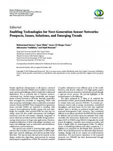
interface Timer { command result t start(...); command result t stop(); event void fired(); } generic configuration SingleTimerC() { provides interface Timer; } implementation { components TimerC; Timer = TimerC.Timer[unique("Timer")]; } module AppP { uses interface Timer; } ...C code ... configuration AppC {} implementation { components new SingleTimerC() as MyTimer, AppP; AppP.Timer -> MyTimer.Timer; } AppM SingleTimerC
Timer Interface Application Component T2 Component
TimerC
Figure 1: Sample nesC code and its pictorial representation. AppC wires the AppP module to the to the Timer interface provided by the newly instantiated SingleTimerC configuration. SingleTimerC exports a Timer interface from TimerC, denoted by the pass through connections (there is no intermediate code).
lic ones in C. Figure1 shows some sample nesC code, adapted from a TinyOS example to show component instantiation, and a corresponding pictorial representation. The nesC concurrency model is based on the TinyOS task abstraction. nesC tasks run atomically with respect to one another. Tasks have no return value and may not take parameters: parameters must be stored as fields of the task’s component. By default, code can only be called from tasks (and not from interrupts). Most basic abstractions, such as sending a packet, fall into this category. Interrupt handlers can only call code that has the async keyword. Examples of async functions include sampling an A/D converter and toggling an LED. The task/async distinction means that a task must be posted if an interrupt handler wants to, for example, send a packet or signal a send completion (neither of which is async). 2.3
802.15.4 and the CC2420
802.15.4 is a recent low power wireless standard [28]. A comparatively high data rate (250kb) at reasonable power cost (15-20mA) has led many sensor platforms to adopt it as a data link protocol. The ChipCon 2420 (CC2420) is the dominant 802.15.4 chip. The CC2420 provides a packet interface. It signals packet reception by triggering an interrupt. If the hardware successfully receives a packet it automatically sends a synchronous data-link level acknowledgment. The software stack is responsible for reading the received bytes out of the chip’s memory over a bus. If this memory overflows, the radio stops receiving packets. A software stack sends a packet by writing it to the CC2420’s memory then sending a transmit command.
This simple hardware interface turns out to have very complicated repercussions for TinyOS, as described in the next section. 2.4
TinyOS limitations
Experience has shown us that TinyOS has three basic limitations: new platform support, application construction, and reliable operation. A typical port of TinyOS to a new platform involves copying a lot of code from an existing one and modifying it where needed. There are hacks to mitigate this somewhat — a platform can “inherit” from another — but supporting new combinations of chips is mostly a case-by-case basis of getting things to work. Additionally, because TinyOS does not define clear abstraction boundaries, components often directly access hardware resources. For example, the micaZ implementation of the CC2420 stack uses a hardware timer for its CSMA backoffs. A new platform that inherits from the micaZ must make sure it does not use this timer elsewhere, but no clear structure defines whether it is being used. TinyOS applications face failures that stem from component composition. Large numbers of components lead to unforeseen interactions and dependencies. For example, on the Telos platform both the CC2420 radio and the flash storage system share an SPI bus; the pins of this bus are also used to connect to external sensors. Including all three in an application requires orchestrating their use very carefully. For example, if the boot sequence tries to initialize the radio and flash system simultaneously, one will fail. Details such as these are the source of many questions on the TinyOS help list. The CC2420 radio itself introduces several reliability challenges for which there are no good solutions. When the TinyOS CC2420 software handles a packet receive interrupt, it reads the received packet in over the SPI and posts a task to signal reception to higher components. Because the task queue is a shared resource, it is possible that the post will fail. This raises a host of problems. The CC2420 hardware successfully received the packet, so it has sent an acknowledgment. But the radio software cannot deliver the packet to the application. Retrying the post requires that someone call into the component again in the future, and there is no good way to ensure this happens (earlier stacks for other chips had periodic interrupt sources). One possibility is using a timer, but the timer system uses the task queue. Another possibility is to wait for another receive interrupt, but if the receive memory overflows, the stack stops delivering interrupts. TinyOS deals with this problem by dropping the packet, even if the hardware has acknowledged it. The problem is even worse for packet transmission. Because transmission is split-phase, higher level components wait for the radio to signal the sendDone() event
before reusing the buffer to send another packet. If the radio cannot post a task to signal the event, then the caller can block indefinitely. TinyOS deals with this problem by breaking its concurrency model: if it cannot post the task, it signals sendDone() in interrupt context. This introduces potential bugs: code written to be run in tasks only (e.g., with no atomic sections) executes asynchronously and might corrupt memory. Furthermore, this latter problem is not limited to the radio stack. Any component that signals completion of a split-phase operation in a task is vulnerable. These failures can propagate between components, causing higher level ones to block forever or suffer race conditions.
The third class of abstraction is physical and shared. Unlike the two more common classes, which depend on compile-time mechanisms to virtualize or check needed properties, physical and shared resources depend on runtime arbitration. While a user of this class of abstraction cannot conflict with other users, it must explicitly request the abstraction before it can use it and must release it when done. Generally, physical and shared resources provide the Resource interface, which has commands for requesting and releasing the abstraction. There are several possible policy implementations of the Resource interface, called arbiters. Examples include round robin and first-come-first-served.
3
3.3
T2 Design Principles
Like TinyOS, T2 is a component-based operating system written in the nesC language. However, T2 avoids many of the problems of TinyOS by using a component architecture based on four design principles. These principles are telescoping abstractions, partial virtualization, static allocation/binding, and service distributions. 3.1
Telescoping Abstractions
T2 provides telescoping abstractions in order to satisfy the requirements of general as well as specialized application domains. Telescoping abstractions provide both a vertical and horizontal decomposition. The vertical dimension spans an individual subsystem (e.g. communication stack), where the higher layers are generally hardware independent and provide simple interfaces. Lower layers, in contrast, can be hardware dependent and provide more powerful interfaces. The structure of these abstractions make it clear to a developer where an abstraction lies in this spectrum, in case an application needs to run on multiple platforms. Horizontal decomposition simplifies porting by allowing reuse of subsystem implementations across different platforms. Mote hardware is built out of standard chips, with well-defined physical interfaces. Reflecting these physical interfaces as platform-independent abstractions such as buses allows reuse of subsystems corresponding to these chips across different platforms. 3.2
Partial Virtualization
T2 abstractions fall into three categories. The top layers of a telescoping abstraction are usually virtual and shared, as one user of an abstraction is hidden from others through software virtualization. This virtualization simplifies application development. Virtual and shared abstractions are generally supported with static allocation (discussed below) through the nesC Service Instance pattern [7]. The bottom layers of a telescoping abstraction are usually physical and dedicated, with only one user of the abstraction.
Static allocation/binding
Because the nesC compilation model allows full program analysis, T2 pushes as much allocation and binding to compile time as possible. This design principle limits flexibility, but makes many OS behaviors deterministic. Dynamic approaches are ultimately a bet that certain circumstances are unlikely (e.g., that every component will need a piece of state at once). Long lifetimes, large numbers, and an uncontrollable environment mean that making wagers is unadvisable. Static allocation means that components allocate all of the state they might possibly need. If a component needs to be able to send a packet, it must allocate a packet buffer. Sometimes, a set of components designed to work together may never send messages concurrently, so only one packet buffer is needed. But the maximal state needed at any time must be statically allocated. Static binding involves pushing as many interface, parameter, and function bindings to compile time as possible. If there are invariants, components and interfaces should reflect them, rather than leave their checking to runtime. 3.4
Service Distributions
On the one hand, arbitrary component composition gives a developer a great deal of power and flexibility when building applications. On the other, it can make building non-trivial applications time consuming and difficult, due to unforeseen conflicts and interactions between these independent elements. Because T2 components need to be usable in a wide range of application domains, they tend to provide only basic mechanisms and leave policies up to higher level code. Pushing all of this complexity into applications increases their complexity. For example, determining when a component is powered on is often left up to the application. T2 improves reliability and simplifies applicationlevel development with service distributions. A service distribution has a set of service components that define and provide its abstractions as services. An application wires only to service components, limiting flexibility but
Platform
MCU
eyesIFX [11]
MSP430
ScatterWeb [24] MSP430 imecCube [32]
MSP430
Telos [21]
MSP430
WISAN [23]
MSP430
iMote2
PXA27X
micaZ [14]
Atmega128
mica2 [33]
Atmega128
BTnode [2]
Atmega128
evb13192 [6]
HCS08
Buses UART/SPI/I2C0, UART/SPI/I2C1 UART/SPI0, UART/SPI1 UART/SPI0, UART/SPI1 UART/SPI/I2C0, UART/SPI/I2C1 UART/SPI/I2C0, UART/SPI/I2C1 UART0, UART1, SPI0, SPI1, I2C UART0, UART1, SPI, I2C UART0, UART1, SPI, I2C UART0, UART1, SPI, I2C UART0, UART1, SPI, I2C
Radio
Flash
TDA5250
at45db
TR1001
microchip 24xx64
HAL
HPL
CC2420
Atmega128 Timer Stack
CC2420
CC2420 Radio Stack CC2420AlarmC
CC2420
strataflash
CC2420
at45db
CC1000
at45db
ZV4002, CC1000
sst39
MC13192
The Hardware Independent Layer provides general, crossplatform abstractions, such as packet transmission and timers. The Hardware Abstraction Layer has usable abstractions that provide the capabilities of the underlying hardware resources, which are usually richer than the HIL. The Hardware Presentation Layer is a thin layer of nesC code on top of the raw hardware, such as pins, interrupts and registers.
increasing reliability. A distribution has internal components that wire underlying implementations in a manner that ensures they will work properly. Finally, a service distribution establishes coherent policies across its services so that the application does not have to.
T2 Core
In this section, we describe the three core parts of the T2 operating system. The first is how it structures application code, chip-specific code, and platform-specific code. The second is its boot sequence. The third is its scheduler. We conclude with a brief presentation of OSKI, T2’s first service distribution. 4.1
TimerMilliC ActiveMessageC
stm25p
Table 2: The Hardware Abstraction Architecture layers.
4
Application Component MicaZ Component Chip Component 32kHz Timer Millisecond Timer Communication
nRF2401
Table 1: Typical WSN platforms and their hardware components. These 10 platforms use 4 different microcontollers, 7 different radios, and 5 different storage chips: there are many possibilities for reuse. HIL
AppM
Decomposition
Table 1 shows a sample of current sensor network platforms and their important hardware components. Although there is a lot of diversity, there are also commonalities. For example, the micaZ, Telos, and iMote2 all share a common radio, the CC2420, while the Telos, WISAN, eyesIFX, ScatterWeb, and imecCube all share a common microcontroller, the MSP430. In prior work, we proposed the Hardware Abstraction Architecture (HAA) to decompose the functionality of an individual subsystem, such as MCU timers [11]. The HAA breaks a hardware abstraction into three layers, described in Table 2. The commonalities across platforms, however, mean that in addition to the vertical decomposi-
Figure 2: The T2 chip/platform decomposition. The CC2420 software depends on a physical and dedicated timer. The micaZ platform code maps this to a specific Atmega128 timer.
tion of the HAA, T2 needs a horizontal decomposition to promote subsystem reuse. To this aim, T2 introduces the concept of chips, self-contained abstractions of a given hardware chip such as an MCU or radio. Each chip follows the HAA model, providing a telescoping abstraction with a HIL implementation at the top. Platforms are compositions of chips. They use static binding to connect chip software stacks to the interfaces they require from each other. T2 has HIL level, microcontroller-independent abstractions of common bus protocols such as I2C, SPI, and UART. This enables protocol-specific optimizations; for example, the SPI abstraction does not have to deal with client addresses, while the I2C abstraction does. Assuming there are implementations for each of a platform’s chips, porting T2 requires little more than connecting buses and other resources through nesC configurations, as shown in Figure 2. 4.2
Boot Sequence
The T2 boot sequence has five steps, some general to T2, some platform specific, and some application specific: initialize the scheduler (T2), initialize hardware (platform), initialize software (platform + application), signal boot() to components (application), and run the main task loop (T2). Hardware initialization is for very low-level operations, such as configuring IO pins and calibrating clocks. As the nesC component model only includes components that are actually used, in T2 these components automatically wire themselves to the boot sequence. Platform components that require a specific initialization sequence can incorporate these constraints into their code and wiring. Initialization is the one time when T2 can block for more than a few microseconds, as it is rare and parallelism is rarely desirable. This boot sequence is different from TinyOS in two respects. TinyOS both initializes and starts any components wired to the boot sequence, and components are expected to initialize, start and stop any services they depend on. T2 differs in the first respect in that it starts no components: it just issues a booted event to the top-level application, which can then power on systems as needed.
T2 differs in the second respect because software initialization is generally flat. T2 takes this approach because in TinyOS, general services like timers are initialized and started many times. This is inefficient and, in buggy implementations, can lose requests or cause call loops. Also, the deep init/start/stop semantics cause many runtime failures. For example, on the Telos platform, stopping the radio to save power also stops the SPI bus, rendering flash storage inoperable. T2 solves this problem at lower levels either with the Resource interface (for physical and shared) or with virtualization. It solves this problem at the application level using service distributions, which provide higher-level interfaces to system services, keeping track of service clients to provide a coherent power management policy. 4.3
OSKI
OSKI (OS Key Interfaces) fulfills the two goals of a service distribution, simplifying application development and managing component interactions to improve reliability. OSKI services are virtualized versions of underlying T2 subsystems, and provide a coherent power management policy. OSKI keeps a statically allocated bitmask to keep track of which clients are active, ensuring that no service stops prematurely. Bitmasks are more reliable than reference counts, as they are not affected by inadvertent multiple starts or stops. Internally, OSKI orders subsystem initialization and parameters, so that all an application has to do is wire to services and start them when needed. We present the OSKI API for timers and communication in Sections 5.2 and 6.3.
5
Figure 3: Timer interfaces and components (simplified). TimerMilliC VirtualizeTimerC AlarmToTimerC
Scheduler
The T2 scheduler is based on the observation that while TinyOS allows tasks to be posted many times, in practice they almost never are. Instead, when a task runs it performs all outstanding work. The ability to post multiple times is unnecessary flexibility that introduces significant reliability issues. Therefore, T2 tasks have different semantics: a task can always be posted unless it is already in the queue. The scheduler provides these semantics by using static allocation to reserve a slot in the queue for each task. This requires a byte of RAM per task (TinyOS uses two bytes per entry to store a pointer), but code can assume that task posting will never fail. 4.4
interface Timer { command void startPeriodicAt(uint32 t t0, uint32 t dt); command void startOneShotAt(uint32 t t0, uint32 t dt); command void stop(); event void fired(); } interface LocalTime { async command uint32 t get(); } interface Alarm { async command void startAt(width t t0, width t dt); async command void stop(); async event void fired(); }
Timers
In most mote applications, execution is driven solely by timer events and the arrival of radio messages. Responding to external stimuli via interrupt requests only makes sense if the power usage of an always-active hardware sensor is lower than the cost of polling it with the processor. Additionally, energy constraints require that radios be off most of the time, so timers generally drive the
TransformAlarmC
Millisecond Timer Millisecond Alarm Millisecond Counter HPL Timers/Counters HIL Component Timer Library Component Atmega128 Component
MilliCounterC Atm128AlarmP HplTimer0C
Figure 4: Timer stack on the micaZ and mica2 platforms.
radio. Correspondingly, a critical part of a mote OS is having a reliable, powerful, and efficient timer system. This system must provide a standard interface to an arbitrary number of timers, to support portable, composable high-level services. Timer rates vary from a few events per day to sampling rates of 10kHz or even higher. Finally the timer system must allow the mote to be placed in a low-power mode (a few µA) between timer events. Mote microcontrollers come with a wide variation of hardware timers. For instance, the ATmega128 has two 8-bit timers and two 16-bit timers, while the MSP430 has two 16-bit timers. All of these timers come with different clocking options, compare and external event capture registers, etc. A standard interface cannot hope to provide a consistent view of this hardware diversity. Instead, T2’s timer subsystem follows the telescoping abstraction principle. At the top-level are virtualized and shared timers with a standard, limited interface. These virtualized timers are statically allocated to different services. Underneath, there are microcontroller-specific interfaces to the hardware timers. These timers are physical and dedicated, e.g., providing the virtual timers, or doing cycle-counting for benchmarking purposes. 5.1
T2 Timer Subsystem
The Timer interface (Figure 3) provides 32-bit periodic and one-shot timers. To support accurate timing, these timers include a starting time (t0). Times and intervals are 32-bit values whose granularity depends on the component providing the Timer interface (see below). The
LocalTime interface allows a component to determine the current time in terms of a local clock, which can wrap-around. Values of t0 greater than the current time refer to the past, not the future. These interfaces are offered by one or more components which expose virtual timers at different time granularities. T2 platforms must offer a TimerMilliC which provides a millisecond granularity timer. Platforms may provide other granularities, e.g., 1/32768s and µs. A T2 platform must also provide access to each hardware timer using the Alarm interface (Figure 3). The Alarm interface serves two purposes. First, T2 has a reusable component library that can build up a full Timer system from a single Alarm. Second, since Timer is taskonly, it introduces some jitter. Unlike the Timer interface, the Alarm interface is only one-shot and is async. Applications or components which need low-jitter timer events (high sampling rates, MAC timers) use an Alarm interface, and therefore either depend on platform interconnect code (e.g., CC2420AlarmC in Figure 2) or are platform specific. In this latter case, standardizing the Alarm interface reduces porting effort. Figure 4 shows the mica family’s timer subsystem. Low-level components (HplTimer[0-3]C) provide dedicated access to the two 8-bit and two 16-bit timers of this family’s ATmega128 microcontroller. The Atm128AlarmP component transforms this low-level interface into an Alarm interface. The T2 timer subsystem is built over the 8-bit timer 0, as it is the only timer that can run when the ATmega128 is in its low-power mode. The other hardware timers are available to the platform or applications; on the micaZ, timer 1 is used for the CC2420 radio and is exported through the platform CC2420AlarmC component (Figure 2). 5.2
Timers in OSKI
OSKI timers have one fidelity: milliseconds. While microcontrollers can generally provide higher fidelities (e.g., 32kHz), some, such as the Atmega128, cannot do so in an energy efficient manner. Applications obtain a timer by instantiating an OskiTimerMilliC component, which offers the Timer interface (Figure 3). As the set of Timer interfaces implicitly define activity (individual start/stop), the OSKI timer service has no service-level start/stop abstraction.
6
Communication
Networking dominates sensor node software. It dominates energy considerations: the high order bit in power management is turning off the radio. It dominates RAM considerations: when compiled for the mica2 platform, the TinyDB system dedicates half of its RAM to packet buffers and routing tables. Therefore, the interfaces to and implementation of networking stacks have signifi-
micaZ Packet Buffer
Header
Data
Serial Packet
Data
CC2420 Packet
Data
Footer + MD
Figure 5: A T2 packet buffer. MD is metadata that is not transmitted, such as acknowledgment reception and timing. The footer box represents allocation but not necessarily placement. Packets are generally contiguous, so a short packet may store its footer in the data region.
cant effects on the rest of the system. In this section we describe two communication stacks and their structure. While motes are generally purely wireless, most deployed networks have one or more tethered motes that are connected to a higher power device through their serial port. Tethered motes take one of two forms. They are either a node running the same software as other nodes, but which forward data to the serial port instead of the radio (base stations), or they are nodes that act as transparent serial/radio forwarders (bridges). Tethered motes, combined with the fact that some platforms have multiple radios [2], means that OS networking abstractions must support cheaply passing packets between different stacks. The T2 network stacks resemble TinyOS in that they follow a zero-copy policy. T2 achieves this by requiring a platform to define its packet format. Figure 5 shows the structure of a T2 packet. A T2 packet has a fixed size data payload which exists at a fixed offset. Data-link headers and footers are right and left justified accordingly. This structure allows a node to receive a packet with one data-link level stack and pass it another stack that has completely different headers without requiring any data shifts or copies. The HIL of a data link stack is an active message interface. Layers on top of this interface may introduce new headers. For example, tree-based collection routing usually embeds a source address, per-hop destination address, and a packet sequence number. T2 uses static binding to allow protocol layering with zero copies. A layer determines the offset where it can safely write by calling the Packet interface of the layer below. Since these relationships are static, nesC collapses several calls through components into a single constant. 6.1
CC2420 Communication
The problems posed by the CC2420 stack in TinyOS led us to completely redesign most of its decomposition. In T2, the majority of CC2420 code is platform independent, requiring only four abstractions from a platform: the interrupts the chip triggers (physical and dedicated), a capture register for timing (physical and dedicated), an SPI bus for communicating with the chip (physical and shared), and a 32khz async timer for CSMA backoff and acknowledgment timeouts (physical and dedicated). Figure 6(b) shows this decomposition. The T2 CC2420 stack uses the Resource interface to
ActiveMessageC CC2420ActiveMessageC
Active Message CSMA 802.15.4 Packet 802.15.4 Specific
CC2420RadioP
CC2420 Registers CC2420 FIFO Memory Interrupts SPI Bus
CC2420P HplCC2420PinsC
CC2420 Component/Wire MicaZ Component/Wire Atmega128 Component
Atm128SpiMasterC
CC2420RadioC
Atm128IOC
(a) The telescoping abstraction of the CC2420 radio stack. ActiveMessageC is platform independent and can encapsulate many data link layers. It is a simple wrapper around CsmaActiveMessageC, which provides additional CSMA-based interfaces. This sits on top of CC2420RadioC, which provides 802.15.4 raw packet and configuration interfaces (such as address decoding).
(b) A partial decomposition of CC2420RadioC on the micaZ platform. CC2420RadioP uses interfaces that access the chip’s registers and packet memory through an SPI protocol. It also depends on handling interrupts for events such as packet reception. The micaZ platform code exports the bus and interrupts from Atmega128 abstractions.
Figure 6: The T2 CC2420 stack. // TinyOS approach uses interface Register; call Register.cmd(CC2420_STXON); call Register.write(CC2420_MDMCTRL0, modem0Param);
AM Packet Packet Data Bytes Encoded/decoded bytes Packet Format
SerialActiveMessageP SerialDispatcherP SerialPacketInfoP
// T2 approach uses interface CC2420StrobeRegister as STXON; uses interface CC2420RWRegister as MDMCTRL0; call STXON.cmd(); call MDMCTRL0.write(modem0Param);
Platform Independent Protocol Specific Platform Dependent
SerialP UART Serial Packet
F P S D Data
CRC F
Figure 7: Static binding of CC2420 registers. Strobe and read/write registers share an address space. In TinyOS, the address is a runtime parameter, requiring runtime checks. T2 uses static binding so no checks are necessary, yet the implementations do not replicate code.
Figure 8: The T2 serial stack. F is a framing byte, P is a protocol type for the serial stack, S is a sequence number for data packets, and D is the packet format byte. The arrows show which component is responsible for each header byte.
arbitrate for the SPI bus. On the micaZ platform, the SPI bus is dedicated and arbitration always succeeds (nesC’s inlining and full program analysis removes most of the overhead). On the Telos platform, the SPI is shared with other devices. Of course, if another Telos system holds onto the bus for long enough, the CC2420 packet buffer will fill up and drop packets. T2’s task semantics mean that the race condition problems which plague TinyOS do not exist. The stack waits until it signals the sendDone() or receive() event before returning to an idle state. The worst that can happen with lots of tasks (heavy load) is long queue waits, which will decrease packet throughput: they do not, however, introduce race conditions or crash the system. Internally, the CC2420 stack uses static binding heavily. For example, controlling the CC2420 requires accessing hardware registers through commands over the SPI bus. In the TinyOS stack, accessing registers is a very general interface and requires several runtime checks. In T2, the register interfaces are much more constrained and written in a way to not require these checks. Figure 7 illustrates how. This structure has the additional benefit that a programmer can see what registers a component accesses by looking at what interfaces it uses, rather than having to read through the implementation. Finally, the CC2420 stack uses telescoping abstractions to allow components to access CC2420-specific
functionality, as shown in Figure 6(a). Components can wire to the platform-independent component ActiveMessageC, control CSMA parameters by wiring to CC2420ActiveMessageC, or directly access the 802.15.4 packet layer by wiring to CC2420RadioC. 6.2
Serial Communication
Bridges and base stations have very different requirements. Base stations wish to communicate in terms of radio independent OS-level packets, while bridges are a transparent translation between media, therefore wish to communicate in terms of radio specific packets. TinyOS addresses this problem by requiring all packets over the serial link to be radio packets. On one hand, this approach means that the serial and radio stacks can share packets, freely passing buffers between queues. On the other, it means that each platform talks a different format over the serial port and so requires different PC software. Platform family compatibility complicates this further. For example, although the micaZ and Telos share a radio format, the micaZ uses the mica2 serial format to maintain backward compatibility with tools. This discrepancy has caused a lot of confusion among users. T2’s serial stack solves these compatibility issues by providing both forms of communication. The serial stack supports multiple packet formats. Since T2 message buffers are right justified to the internal data payload, the
serial stack needs to know the size of a format’s header to properly read in a packet. The stack uses static binding to make an inexpensive call to determine the proper offset. A program that supports a packet format wires an implementation of this call (a SerialInfo component) to the stack. Base stations support platform-independent packets, while bridges support radio-specific ones. Figure 8 the structure of the stack and how it relates to the actual serial packet format. The serial stack’s telescoping abstraction lets application wire in new packet types (e.g., for low-level operations such as ping) if needed. The T2 serial stack structure supports greater platform diversity. In TinyOS, adding a new platform requires modifying the PC-side toolchain to recognize a new packet format or having a platform pretend to be an existing one. This has been the source of many development headaches (e.g., the fact that the micaZ looks like a mica2). As deployments commonly use base stations (rather than bridges, which are for development), tools can now easily incorporate new platforms. Supporting a new UART requires implementing a simple byte interface (94 lines of code on the Atmega128), while supporting a new packet type requires implementing a SerialInfo component (9 lines of code for the CC2420). 6.3
Communication in OSKI
OSKI builds three services over T2’s communication stack: AM for node-to-node messages, Broadcast for broadcast messages, and Uart for serial communication. All of these services have a ServiceC client component for starting and stopping as well as SenderC and ReceiverC components for actual communication. Every sender and receiver component takes a numeric identifier as a parameter to distinguish different instances of the service. Senders embed the parameter in a packet header, and the OSKI internals uses it to dispatch to the correct receiver.
7
Evaluation
In this section, we evaluate how well T2 achieves its goals. We quantify the costs of these improvements by comparing T2’s static resource utilization (code size and RAM), dynamic resource utilization (CPU cycles, which quantify the OS energy cost), and performance (network bandwidth) with that of TinyOS. 7.1
Simplifying Platform Development
Two main factors simplify platform development in T2. First, the telescoping abstraction principle means that platforms are broken up into subsystems corresponding to individual chips. We evaluate how this decomposition simplifies the development of a new platform, using their radios and microcontrollers as examples. Second, each subsystem is broken up into many individual layers. We
Chip msp430 atm128 cc1000 cc2420
Total PSLOC 4400 3142 1705 1733
(a) Chip PSLOC
Processor Radio Platform Percentage
mica2 3142 1705 228 13%
micaZ 3142 1733 248 14%
Telos 4400 1733 192 11%
(b) Platform Interconnect PSLOC
Table 3: PSLOC of the mica2, micaZ, and Telos platforms and their underlying chips. Radio interconnect code is 11-14% of the radio chip implementation and 3-5% of the overall source base.
show, using the example of timers, how this vertical decomposition allows using a reusable component library, easing timer implementation for a new microcontroller. 7.1.1
Chips and Interconnects
To illustrate the impact of chips on the platform building process, we examined the code that defines the binding between chip abstractions. We use physical source lines of code (PSLOC) [20] as an approximate indication for the amount of effort the platform developer has to invest in order to build a platform out of available chip abstractions. The hope is that the code to incorporate chips into a new platform (once per platform) is small compared to the code written for each chip (once for many platforms). Table 3(a) shows the total PSLOC count for radio and microcontroller chips that T2 currently supports. The radio chip usually has the most interconnect demands. For example, the CC2420 requires (Section 6.1) interrupts, a capture register, SPI, and a 32kHz Alarm (Figures 6(b)), and the CC1000 has similar requirements. Thus radio integration overhead is a good worst case for other, simpler chips such as nonvolatile storage. Table 3(b) shows the comparative sizes of the MICROCONTROLLER, radio, and interconnect code for the mica2, micaZ and Telos platforms. The platform-specific interconnect code is at most 5% (micaZ) of the chip abstractions (and 14%, demonstrating significant code reuse. 7.1.2
Reusable Hardware Libraries
Chip-specific implementations often have commonalities, such as the Alarm to Timer transformation in timer stacks. These commonalities allow reusable hardware library components, simplifying platform development. Table 4 shows this reuse in T2’s timer subsystem on the mica2 and Telos platforms. We break the code down into configuration code, algorithmic code and register wrapper code. Although more than half of the total code written is platform-dependent, much of it simply connects components together (configuration code) or provides convenient shortcuts for accessing hardware registers (register wrappers). The difficult code to write and debug – timer virtualization over a single hardware timer resource, transitioning timer-related interrupts to the synchronous task con-
HW independent
configurations and interfaces algorithmic code Total
mica2 62 359 421
Telos 62 359 421
HW dependent
configurations and interfaces algorithmic code register wrapper code Total
128 102 71 301
362 138 353 853
58%
33%
Reuse percentage
Table 4: Breakdown of the timer subsystem in PSLOC.
text, and transforming arbitrary hardware timer widths to a common format – resides in the reusable hardware library. Bringing up a timer stack on a new microcontroller requires writing HPL access functions for each timer register and code for the low-level Counter and Alarm interfaces. T This last task requires fewer than 150 lines on both the mica2 and Telos platforms. 7.2
Simplifying Application Development
T2 simplifies application development in two ways. First, high-level applications can be built on top of a service distribution. As the service distribution handles all of the complexity below its abstraction boundary, the application does not have to simultaneously manage abstractions at the low-level (e.g., SPI bus power state) and high level (e.g., query processing). Admittedly, no large applications yet run on T2; as service distributions grew from our experiences building such systems [19, 31, 7, 27, 9], however, we believe they will be successful. For example, consider managing the power state of the radio. An application may have several concurrent network services running (e.g., routing and code propagation). Components are independent units, but these components must collaborate to manage the power state. OSKI’s Service interface provides a simple solution to this problem. Second, telescoping abstractions and static binding simplify building highly optimized applications. Telescoping abstractions give components options besides directly accessing hardware, which bypasses the component graph and precludes compile-time checks. Static binding enables these compile-time checks: nesC has mechanisms, for example, to check that two components do not accidentally both wire to a dedicated resource. 7.3
Reliability
To validate that T2 improves system reliability, we constructed two stress cases. The first is a simple sense and send application that samples a sensor at 1kHz and continuously reports the results over the radio. We tested this application on the micaZ platform. With a two entry task queue, the TinyOS version crashes (stops sending messages) after a few seconds to a few minutes. Admittedly, this result is for artificially high message rates and a very short task queue. However, reducing the message
rate only lowers the probability of problems, rather than eliminating them. This is not acceptable for applications which are expected to run for months to years. Similarly, while it is possible to increase the task queue size to fix this particular application, there is no way to determine a safe queue size for an arbitrary one, especially given that tasks may be posted multiple times. The second stress case involves the CC2420. To quantify how often the TinyOS CC2420 stack might introduce race conditions into a problematic application, we instrumented the stack to count how many times it issued a synchronous event in an async context. We then ran the same communication application as in the bandwidth experiments in Section 7.4.3, except that the application included a task that degeneratively reposted itself enough to fill the task queue. This degenerate task had three effects. First, it caused the timer system to fail. Second, the stack communication rate dropped by approximately 50%. Third, after running for one minute, the stack had violated the TinyOS concurrency model 48 times. The best analogy to this behavior would be for a thread library to once a second randomly ignore a request to acquire a mutex. While in lightly loaded systems this might go unnoticed, under load, large scale, or long lifetimes it would fail. None of these reliability failures occur in T2. The sensing application ran overnight with no problems. A degenerate task does not disrupt timers and does not reduce throughput. The CC2420 stack does not ever violate the task/async boundary. 7.4
Resource Usage and Performance
The four design principles used in T2 can lead to increases in code size, RAM and CPU usage. Service distributions and telescoping abstractions break subsystems into more layers, potentially increasing code size and CPU usage. Static allocation may increase RAM usage by reducing the amount of runtime sharing between components. Finally, virtualizing or sharing a resource at run-time requires extra RAM and CPU cycles. However, several factors mitigate these resource impacts. First, the nesC compiler performs extensive inlining (The compiler only inlines small and called-once functions, thus decreasing rather than increasing code size). Combined with dead-code elimination, this reduces the impact of breaking applications into many small components [7]. Finally, the elimination of runtime failures due to static allocation, virtualization and resource sharing often simplifies components, allowing the removal of, e.g., state variables. We compare TinyOS’s and T2’s resource usage and performance in three ways. First, we look at the core OS cost – the scheduler overhead. Next, we compare the code size, RAM usage and CPU cycles of four simple
Application Null
Blink
RadioSenseToLeds
SerialBridge
mica2 micaZ Telos mica2 micaZ Telos mica2 micaZ Telos mica2 micaZ Telos
TinyOS code / ram 434 / 19 464 / 19 1056 / 20 1890 / 69 1920 / 69 2838 / 62 9538 / 400 8134 / 300 13988 / 285 11380 / 1986 9804 / 1900 12102 / 1844
T2 code / ram 494 / 3 440 / 2 1510 / 6 2270 / 53 2216 / 52 2938 / 61 10922 / 231 10808 / 246 12238 / 238 14520 / 1444 14330 / 1447 12202 / 1431
Table 5: Code and RAM sizes for simple applications.
applications. Finally, we evaluate the OS’s performance by comparing their sustainable maximum bandwidth. 7.4.1
Scheduler Overhead
The scheduler imposes two kinds of overhead. The first is the cost of posting and executing a task, the second is the cost of checking that the task queue is empty and going back to sleep (this has to be done after every interrupt). We wrote two simple applications to measure these costs on the micaZ platform, using a hardware timer to count processor cycles. We measured the cost of posting and executing a task using a simple task that always reposts itself. We measured the cost of checking the task queue is empty by instrumenting the scheduler. Posting and executing a TinyOS task takes 80 cycles, while checking that the task queue is empty takes 26 cycles. The T2 scheduler takes 103 cycles to post and execute a task, and 20 cycles to test for an empty task queue. The relative overhead of the TinyOS vs T2 scheduler will thus depend on the ratio between the number of interrupts taken and the number of tasks posted by an application. These small differences will not have a significant affect on overall CPU usage. As noted in Section 4.3, the T2 scheduler allocates one byte per task rather than have a fixed size (8) task queue with two byte entries. For simple applications, such as SerialBridge with its five tasks, this saves 11 bytes. For the largest TinyOS application, TinyDB, which has 28 tasks, the T2 scheduler costs 12 bytes. However, even this cost is often mitigated by simpler state management, as a component does not need to keep track of whether a task has already been posted. 7.4.2
Application Resource Usage
We consider the RAM size, code size, and CPU utilization of four simple applications: Null, the simplest, donothing program; Blink, which blinks a motes LEDs; RadioSenseToLeds, which reports sensor values over the radio; and SerialBridge, which is the standard serial-radio bridge. We compare resource usage on the mica2, micaZ and Telos platforms. Table 5 shows the results. For each application and operating system, the first number is the code size and
Application Blink RadioSenseToLeds SerialBridge
mica2 micaZ mica2 micaZ mica2 micaZ
TinyOS (kcycles/s) 8.0 8.0 240 9.1 206 8.0
T2 (kcycles/s) 5.4 5.4 186 7.5 186 12.3
Table 6: CPU usage for simple applications.
the second RAM usage, both in bytes. The extensive cross-component inlining performed by nesC makes it hard to explicitly attribute code to a particular component. Nevertheless, by examining code sizes with inlining disabled, we observed that the main increases of code size in T2 are due to a more complex timer system, a more flexible serial port protocol and a better quality random number generator. The more complex time system costs about 300 bytes on the mica family, as seen in Blink. The better random number generator is used by the mica2 radio, and adds about 1kB to the RadioSenseToLeds and SerialBridge applications. Finally, the increase in the serial port protocol size is visible on all platforms in the SerialBridge application. The RAM usage is comparable or lower in T2. A cleanup of the mica2 radio stack saved 150 bytes in T2 (see RadioSenseToLeds). The difference in RAM for SerialBridge is due to a very large task queue in the TinyOS version, which was recently added “to lower the chance of a [task] post failure”. We also compare the CPU usage of the Blink, RadioSenseToLeds and SerialBridge applications, on the mica2 and micaZ platforms – the Telos T2 support is still in development and not completely stable. The RadioSenseToLeds application was ran alone, so sent a message a second and did not receive anything. The SerialBridge application was run with another mote sending a message a second, leading to one radio message reception and one serial message transmission per second. We ran these applications for 30 seconds, instrumented to count the number of CPU cycles spent in the scheduler, tasks and interrupt handlers. Table 6 reports these results, averaged over three runs, in cycles / second. These results show that on Blink and RadioSenseToLeds T2 is more efficient than TinyOS. The higher CPU usage in SerialBridge is due to higher overhead in the serial port protocol – we verified this by testing a version of SerialBridge with serial port transmission disabled, giving a CPU usage of 5.1kcycles/s on the micaZ in T2. As the serial protocol is generally used on motes connected to PCs, its CPU efficiency is not critical. While these results are only for very simple applications, they do show that T2 has comparable resource usage to TinyOS applications. In particular, we see that using a statically allocated task queue can save, rather than cost, RAM (see SerialBridge).
Packet Size TinyOS T2 Improvement
One-Way 40B 14B 200 246 380 616 90% 150%
Two-Way 40B 14B 254 362 386 648 51% 79%
Table 7: Packet per second throughput for the CC2420 stack on micaZ.
7.4.3
Network Performance
We compare the network performance of T2 and TinyOS on the micaZ platform. The major difference between the two radio stacks is that TinyOS uses larger and more monolithic hardware abstractions, and assumes it can freely use shared resources, such as the SPI bus. Additionally, TinyOS uses more run-time parameters. We compared the two with simple applications that send packets as fast as they can (calls send() in the sendDone() event). We ran two separate experiments. In the first, we measured single node bandwidth by having one node transmit and one node listen. In the second, we had two nodes try to send packets as quickly as possible. We ran each experiment twice, once with large packets (40 bytes, including all headers and footers) and once with small packets (14 bytes). We measured average packet per second communication over a 60 second window (the nodes communicated for 60 seconds then stopped). Each experiment had five separate runs; the results for the runs were all within 3% of each other. Table 7 shows the results. T2 shows a 51-150% performance improvement over TinyOS. The TinyOS stack is unable to process packets at same rate as T2. This is due to two factors that we were able to identify. First, both stacks flush the receive memory whenever they think there is a problem, but the TinyOS stack has a much broader definition of what constitutes a problem. Second, the TinyOS stack reads packets in task context, incurring task latency between a receive interrupt and actual reception, while the T2 stack starts the split-phase SPI read in the async interrupt handler.
8
Related Work
TinyOS [15] is the dominant sensor network operating system today. Designed in concert with the nesC language [8], it relies on language mechanisms to enforce and support its design methodology. T2 builds on TinyOS’s successes, but casts off decisions which experience has shown to be problematic. Other sensor OSes, such as MOS [1] and SOS [10], have taken more traditional approaches. Rather than use a new language, they are C based. MOS provides a microthreaded UNIX-like environment with blocking operations: a thread configures a sensor with a dev ioctl call and samples it with dev read. It therefore follows the UNIX “everything is a file” abstraction, via a few calls with a large number of parameters. This pushes error checking to runtime, as the interfaces do not express
the constraints underlying resources. For example, a program can try to read from an A/D converter pin that does not exist. TinyOS’s (and T2’s) wiring model catches such errors at compile-time. The SOS operating system is also written in C, but is otherwise similar to TinyOS, as it is component based and has a run-to-completion concurrency model. However, it is less restrictive than TinyOS. Rather than a single FIFO task queue, SOS has priority queues. SOS also provides mechanisms for dynamically linking new binary components. However, RAM constraints prevent linking correctness checks from being foolproof. Furthermore, while checking individual components may be tractable, the most difficult errors and bugs are often the result of combinations of components and their interactions. Leaving these complexities to a dynamic environment makes diagnosing problems even more difficult. Design differences aside, MOS and SOS both still suffer from the same problem as TinyOS does with its task queue. In MOS, a program has a fixed maximum number of threads. While they are usually allocated at boot time (making errors easy to find), they can also be allocated at runtime, opening the possibility of failure. SOS uses a memory pool to dynamically allocate inter-component messages. While the runtime propagates allocation failure as an error to the message passing call, few components check for this, and as the complexities of the CC2420 stack show, sometimes there is no good way to deal with such a failure. There are many component languages besides nesC, designed for regular programming tasks [34, 5, 22, 4], for hardware design [16], for distributed systems [13] or for modeling [29]. Most of the implementation-oriented work has focused on large systems, with two major exceptions. The Flux OSKit [5] is a component system designed for building desktop-style operating systems, which have very different resource and reliability issues than sensor networks, while the Koala system [34] is designed for consumer electronic (CE) devices (such as TVs). On one hand, Koala’s intended domain has similarities to sensor networks: CE devices require rapid development, but software must be very reliable as there is no way to upgrade it once deployed. On the other hand, the design space is also very different: CE devices are a narrow set of product lines that evolve over time. Therefore, Koala takes an object-oriented approach, so software for a new model can extend prior functionality. Koala is intended for the user interface to product families within a few application domains, while T2 is intended to be an operating system for as broad a spectrum of application domains as possible. The Snack [9] system builds applications by automatically combining system modules while resolving application constraints and cross-service interdependen-
cies. Service distributions build on Snack’s observation that unforeseen interactions are a major source of complications when developing applications with software components Just as TinyOS is about discovering system boundaries, service distributions draw the line between applications and the operating system – providing functionality without the complexity.
9
Discussion
T2 borrows many of TinyOS’s design decisions because they have, for the most part, been successful. The CPU is mostly idle in a wide range of sensor network applications [25]. Instead of heavy processing, the CPU’s major responsibility is to move data from one peripheral to another (e.g., from sensor to storage, from storage to radio), perhaps processing it a bit along the way. Therefore, a data flow centric approach, with events and lightweight handlers, is better suited to sensor applications than a threaded approach. TinyOS’s flexibility and few restrictions makes it an excellent research tool. A new routing protocol is a small handful of components that sit on top of the data link layer, a new MAC protocol is a replacement for one or more of the components within the data link layer. Having complete control of the entire system makes it easy to addressing narrow and specific research questions, whose experimental methodologies often require settings that a real deployed system would rarely encounter. When it comes to larger and more complex systems, however, this power is a liability. TinyDB, for example, was the first large system built for TinyOS. After three years, small teams of researchers were still unable to achieve reasonable data delivery rates [30, 31], citing subsystem interactions as the cause. While the T2 scheduler improves system reliability, it still has limitations. Like TinyOS and SOS, a run-tocompletion model means that an infinite loop can, like an overflowing task queue, cause the system to fail. However, compared to the task queue, which involves interactions between many components, checking the code in a task is a much easier local problem. In practice, while programmers occasionally encounter this problem, it is generally very early in the development cycle (e.g., the first installation). Similarly, while the nesC component model provides structure to limit memory access errors, components that pass variable size memory regions around can still have faults. For example, while developing the T2 CC2420 stack, we encountered an off-by-one error that caused a length byte to be overwritten, leading the SPI bus to read into the entire program rather than just a buffer. However, in the entire development cycle of tens of thousands of lines of code, this was the only such bug we encountered. The problems that operating systems such as T2,
TinyOS, and SOS face stem from a basic tension in component systems between local independence and global properties. On the one hand, components are intended to be completely independent, black-box functionality that can be quickly incorporated into a program. On the other hand, they inevitably share resources, and therefore composition decisions affect global system behavior. The application specificity of sensor networks means that no single global policy is suitable for addressing such global issues. For example, one complaint often made about TinyOS is its lack of scheduling priority levels. At first glance, this idea makes sense, as depending on the task, latency can have a wide range of effects, including dropping packets, reduced bandwidth, and timer jitter. But priority schemes raise the follow-up question: who specifies the priorities? Depending on the application, each of the previously mentioned effects could be negligible or serious. A communication stack that assumes it has the highest priority can cause an application that cares about timer precision to fail. Our best solution to this conundrum – leaving task priority assignment to the application – is problematic: the application writer has to correctly figure out the relative importance of thirty or more tasks. Thus we believe that avoiding priorities is a good example of limiting flexibility to improve the reliability and usability of the system. As many of the figures have shown, one result of this tension is that T2 does not always have monolithic layers. Rather than just placing components above or below a layer, many compositions involve placing components in between layers (e.g., CC2420PlatformAlarmC in Figure 2), or both above and below (e.g., SerialActiveMessageP and SerialPacketInfoP in Figure 8). Ultimately, T2’s four design principles are about component composition and boundaries. They help manage the tension between local independence and global properties. Telescoping abstractions allow developers to consciously choose a point between portability and functionality. Partial virtualization allows compositions to share resources implicitly through virtualization and explicitly through the Resource interface, and to deny sharing when necessary. Static allocation and binding reduces unforeseen interactions and makes the relationships between components as explicit as possible. Finally, service distributions establish a boundary between application-level code and OS services. A service distribution can reorganize and change underlying implementations without requiring application modifications.
10
Conclusion
T2 takes five years of development with sensor networks and tries to create a fresh start, defining a component architecture that will be effective and useful in the long term. It is still very much a work in progress, and in-
cludes several subsystems we do not discuss here, such as power management, sensors, and non-volatile storage. Platform evolution, emerging applications and increasing experience in the user community will drive future T2 evolution. Specifying interfaces is the most challenging aspects of nesC development, as changing them requires changing every component that uses them. The lack of boundaries in TinyOS complicates this problem, as applications often access interfaces that were initially intended to be internal. In this paper, we showed how applying four design principles to component architecture in T2 increases its reliability, decreases its overhead, simplifies application construction, and makes porting to new platforms easier. While TinyOS and nesC are about creating reusable components, T2 is about composing components and building reliable applications.
References [1] H. Abrach, S. Bhatti, J. Carlson, H. Dai, J. Rose, A. Sheth, B. Shucker, J. Deng, and R. Han. MANTIS: System Support for MultimodAl NeTworks of In-situ Sensors. In Proceedings of the Second ACM International Workshop on Wireless Sensor Networks and Applications (WSNA), 2003. [2] J. Beutel, M. Dyer, M. Hinz, L. Meier, and M. Ringwald. Abstract: Nextgeneration prototyping of sensor networks. In Proceedings of the Second ACM Conference on Embedded Networked Sensor Systems (SenSys), pages 291–292, New York, NY, USA, 2004. ACM Press. [3] V. N. Ekanayake, C. K. IV, and R. Manohar. An ultra low-power processor for sensor networks. In Proceedings of the ACM Conference on Architectural Support for Programming Languages and Operating Systems (ASPLOS XI), pages 27–36, 2004. [4] M. Flatt and M. Felleisen. Units: cool modules for hot languages. In Proceedings of the ACM SIGPLAN 1998 Conference on Programming Language Design and Implementation (PLDI), pages 236–248, New York, NY, USA, 1998. ACM Press. [5] B. Ford, G. Back, G. Benson, J. Lepreau, A. Lin, and O. Shivers. The flux OSKit: A substrate for kernel and language research. In Symposium on Operating Systems Principles, pages 38–51, 1997. [6] Freescale zigbee/802.15.4 evaluation kit. http://www.freescale. com/files/rf_if/doc/app_note/AN2772.pdf. [7] D. Gay, P. Levis, and D. Culler. Software design patterns for tinyos. In Proceedings of the 2005 ACM SIGPLAN/SIGBED Conference on Languages, Compilers, and Tools for Embedded Systems (LCTES), pages 40–49, New York, NY, USA, 2005. ACM Press. [8] D. Gay, P. Levis, R. von Behren, M. Welsh, E. Brewer, and D. Culler. The nesc language: A holistic approach to networked embedded systems. In Proceedings of the ACM SIGPLAN 2003 Conference on Programming Language Design and Implementation (PLDI), pages 1–11, New York, NY, USA, 2003. ACM Press. [9] B. Greenstein, E. Kohler, and D. Estrin. A sensor network application construction kit (snack). In Proceedings of the Seconnd ACM Conference on Embedded Networked Sensor Systems (SenSys), 2004. [10] C.-C. Han, R. K. Rengaswamy, R. Shea, E. Kohler, and M. Srivastava. Sos: A dynamic operating system for sensor networks. In Proceedings of the Third Internaltiona Conference on Mobile Systems, Appliactions, and Services (Mobisys), 2005. [11] V. Handziski, J. Polastre, J.-H. Hauer, C. Sharp, A. Wolisz, and D. Culler. Flexible hardware abstraction for wireless sensor networks. In Proceedings of Second European Workshop on Wireless Sensor Networks (EWSN 2005), Istanbul, Turkey, Feb. 2005. [12] M. Hempstead, N. Tripathi, P. Mauro, G.-Y. Wei, and D. Brooks. An ultra low power system architecture for sensor network applications. SIGARCH Comput. Archit. News, 33(2):208–219, 2005. [13] A. Herbert. An ANSA Overview. IEEE Network, 8(1):18–23, 1994. [14] J. Hill, M. Horton, R. Kling, and L. Krishnamurthy. The platforms enabling wireless sensor networks. Commun. ACM, 47(6):41–46, 2004. [15] J. Hill, R. Szewczyk, A. Woo, S. Hollar, D. E. Culler, and K. S. J. Pister. System Architecture Directions for Networked Sensors. In Architectural Support for Programming Languages and Operating Systems, pages 93– 104, 2000. TinyOS is available at http://webs.cs.berkeley.edu. [16] IEEE Standard 1076-2002. VHDL Language Reference Manual.
[17] C. Intanagonwiwat, R. Govindan, and D. Estrin. Directed diffusion: a scalable and robust communication paradigm for sensor networks. In Proceedings of the International Conference on Mobile Computing and Networking, Aug. 2000. [18] P. Juang, H. Oki, Y. Wang, M. Martonosi, L. Peh, and D. Rubenstein. Energy-efficient computing for wildlife tracking: Design tradeoffs and early experiences with zebranet. In Proceedings of the ACM Conference on Architectural Support for Programming Languages and Operating Systems (ASPLOS), oct 2002. [19] P. Levis, D. Gay, and D. Culler. Active sensor networks. In Proceedings of the 2nd USENIX/ACM Symposium on Networked Systems Design and Implementation (NSDI 2005), 2005. [20] R. Park. Software size measurement: A framework for counting source statements. Technical Report CMU/SEI-92-TR-020, Carnegie Mellon University, sep 1992. [21] J. Polastre, R. Szewczyk, and D. Culler. Telos: Enabling ultra-low power wireless research. In Proceedings of the Fourth International Conference on Information Processing in Sensor Networks: Special track on Platform Tools and Design Methods for Network Embedded Sensors (IPSN/SPOTS), 2005. [22] A. Reid, M. Flatt, L. Stoller, J. Lepreau, and E. Eide. Knit: Component composition for systems software. In Proceedings of the 4th Operating Systems Design and Implementation (OSDI 2000), pages 347–360, Oct. 2000. [23] E. Sazonov, K. Janoyan, and R. Jha. Wireless intelligent sensor network for autonomous structural health monitoring. In Smart Structures/NDE 2004, 2004. [24] J. Schiller, A. Liers, H. Ritter, R. Winter, and T. Voigt. Scatterweb - low power sensor nodes and energy aware routing. In Proceedings of the Proceedings of the 38th Annual Hawaii International Conference on System Sciences (HICSS’05) - Track 9, page 286.3, Washington, DC, USA, 2005. IEEE Computer Society. [25] V. Shnayder, M. Hempstead, B. rong Chen, G. W. Allen, and M. Welsh. Simulating the power consumption of large-scale sensor network applications. In Proceedings of the Second ACM Conference on Embedded Networked Sensor Systems (SenSys), pages 188–200, New York, NY, USA, 2004. ACM Press. [26] G. Simon, M. Maroti, A. Ledeczi, G. Balogh, B. Kusy, A. Nadas, G. Pap, J. Sallai, and K. Frampton. Sensor network-based countersniper system. In Proceedings of the Second ACM Conference on Embedded Networked Sensor Systems (SenSys), pages 1–12, New York, NY, USA, 2004. ACM Press. [27] R. Szewczyk, J. Polastre, A. Mainwaring, and D. Culler. An analysis of a large scale habitat monitoring application. In Proceedings of the Second ACM Conference on Embedded Networked Sensor Systems (SenSys), 2004. [28] The Institute of Electrical and Electronics Engineers, Inc. Part 15.4: Wireless Medium Access Control (MAC) and Physical Layer ( PHY) Specifications for Low-Rate Wireless Personal Area Networks (LR-WPANs), Oct. 2003. [29] Unified modeling language (UML) specification: Infrastructure, Nov. 2004. [30] G. Tolle and D. Culler. Design of an application-cooperative management system for wireless sensor networks. In Proceedings of Second European Workshop on Wireless Sensor Networks (EWSN 2005), 2005. [31] G. Tolle, J. Polastre, R. Szewczyk, N. Turner, K. Tu, P. Buonadonna, S. Burgess, D. Gay, W. Hong, T. Dawson, and D. Culler. A macroscope in the redwoods. In Proceedings of the Third ACM Conference on Embedded Networked Sensor Systems (SenSys), 2005. [32] T. Torfs, C. V. Hoof, S. Sanders, C. Winters, and S. Brebels. Wireless network of autonomous environmental sensors. In Proceedings of the Third IEEE International Conference on Sensors (IEEE Sensors), 2004. [33] University of California, Berkeley. Mica2 schematics. http: //webs.cs.berkeley.edu/tos/hardware/design/ORCAD_ FILES/MICA2/6310-0306-01ACLEAN.pdf, Mar. 2003. [34] R. van Ommering, F. van der Linden, J. Kramer, and J. Magee. The koala component model for consumer electronics software. In Computer, volume 33, pages 78–85, March 2000. [35] A. Woo, T. Tong, and D. Culler. Taming the underlying challenges of reliable multihop routing in sensor networks. In Proceedings of the First ACM Conference on Embedded Networked Sensor Systems (SenSys), pages 14–27. ACM Press, 2003. [36] W. Ye, J. Heidemann, and D. Estrin. An energy-efficient mac protocol for wireless sensor networks. In In Proceedings of the 21st International Annual Joint Conference of the IEEE Computer and Communications Societies (INFOCOM 2002), New York, NY, June 2002.