They demonstrate that these techniques can be run on hand- ..... and the weights to provide real physical sources and only run ... Cannonball Game.
SIGRAD 2010
Tangible Interfaces using Handheld Augmented Reality P. Rojtberg1 and A. Olwal2 1 TU 2 Kungliga
Darmstadt, Germany Tekniska Högskolan, Sweden
Abstract We present a framework for tangible user interfaces on handheld devices through the use of augmented reality, where virtual objects can be manipulated and arranged using physical objects in the real world. Visual feedback is provided in the high-resolution handheld display, where virtual objects are overlaid onto live video from the camera. The virtual objects are registered and tracked in real-time relative to the physical environment using the device’s camera. Realistic lighting and rendering of high-resolution virtual models is achieved through hardwareaccelerated graphics and shadow mapping. The user can interact with the virtual objects and system parameters both through an overlaid menu interface and through direct touch-screen interaction. We describe our framework, our adaptation of the ARToolKitPlus tracking library for a mobile platform, and a number of interaction techniques that we implemented for a prototype urban planning application. Categories and Subject Descriptors (according to ACM CCS): H.5.1 [Information Interfaces and Presentation]: Multimedia Information Systems—Artificial, augmented, and virtual realities; I.3.6 [Computer Graphics]: Methodology and techniques—Interaction techniques.
1. Introduction An important task in authoring 3D scenes is the navigation of the 3D space. This is necessary to, for example, position objects in the space, but it is also critical to many other tasks. For example, before one can select and change the color of an object, one often has to find a perspective such that the object is visible. Positioning the virtual camera, however, requires similar navigation as for placing an arbitrary object. (See Figure 1.) Placing an object in 3D space not only consists of choosing a 3D vector that represents its position, but also choosing a 3D orientation. Summed up, one has 6 degrees of freedom (DOF) for placing the object. In the best case one would change all 6 DOFs simultaneously for fast placements. (See Figure 2.) One challenge is that this type of input on desktop systems is typically controlled with a mouse and keyboard. The mouse provides relative 2D input, while the keyboard’s modifier keys are used to switch between which 2D dimensions the mouse is controlling at a given time. This, however, means that the user can only manipulate 2 dimensions simultaneously, which in theory could take 3 times longer for getting 6 DOFs due to the implicit temporal sampling.
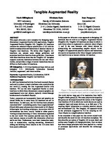
Figure 1: An augmented reality scene, viewed through the screen of a mobile device that is running our framework. The scene contains virtual buildings that the user can position through the tangible manipulation of multiple cameratracked markers in the real world.
However, often only either the orientation or the position of an object has to be changed, which requires only 3DOF.
P. Rojtberg & A. Olwal / Tangible Interfaces using Handheld Augmented Reality
uses 6DOF tracking of the camera to register rendered computer graphics overlaid on a live video stream of the real world. This allows the use of marker-based AR as a cheap 6DOF input device, as it only requires a camera and printed markers, as shown in Figure 3. Using the position and orientation of the markers as input allows direct positioning of an object in the 3D scene. This interaction can be extended to multiple objects by tracking multiple markers simultaneously and mapping one marker to each virtual object. Using this approach we create a tangible interface for 3D authoring which makes most of the necessary operations spatially seamless [BKP08]. Furthermore, the one-toone mapping gives us spatial references in the real world [HPGK94]. Figure 2: A typical scene for 3D authoring. The camera and the object require 6DOF input and the omnidirectional light requires at least 3DOF to be positioned in space.
In these cases one can try to map the 2D input to 3D to speed up the task. A widely used technique called ArcBall rotation maps 2D movements to 3D rotations [Sho92]. It works by projecting the user’s input onto a virtual sphere around the object. The projected 2D movement results in a 3D arc on the sphere. The object is then rotated in 3D along the trajectory of the arc. While this is generally considered a reasonable mapping of 2D movements to 3D rotations, it is not very intuitive, as the user has to know how the mapping works to perform a predictable rotation. But even then, predicting the projection is not trivial. For certain scenarios it might instead be more appropriate to use 6DOF input devices. Tangibles are particularly interesting, as they support physical manipulation and naturally offer 6DOFs. One might consider using a device with embedded sensors (e.g., accelerometers, gyroscopes and magnetometers† ) to create the tangible objects, but the use of such sensors on a larger scale is limited by issues like performance, resolution, power requirements and cost.
Figure 3: Camera-based marker tracking provides the rotation and translation of the camera relative to marker. Marker-based augmented reality (AR), on the other hand, † http://www.xsens.com/en/general/mti
This speeds up the operations for arranging the scene and is generally a natural choice for interacting with AR environments. There are, however, still operations where 6DOF input is counterproductive. Consider the fine arrangement of a scene where only a small rotation along one axis has to be performed. In this situation only one dimension has to be changed and the involuntarily control of free-hand 6DOF input would most likely affect all other dimensions. In these cases one can apply constraints to limit the dimensions that are affected by the input. While marker-based AR interaction has a number of advantages, as mentioned, most real-world examples do not go beyond just positioning the camera inside a non-interactive scene‡ ,§ .
2. Related Work Rekimoto and Nagao used the term “augmented interaction” already in 1995, when they presented their NaviCam system [RN95]. Their goals were to move from human-computer interaction to human-real-world interaction as this is where the user’s focus actually lies (Figure 4). Furthermore, they wanted to make the interface context-sensitive and narrow the gap between the computer and the real world by making the computer understand real-world events. The NaviCam concept envisioned using handheld devices for interaction and presentation. Due to the limited processing and rendering capabilities on handhelds at the time, the video from the handheld camera was fed to a workstation that did the marker recognition and added the overlays onto the video stream, which was sent back to the handheld display. This still allowed the system to pioneer the proof-of-concept of using a handheld that recognized color codes attached to objects and then displayed a context-sensitive 2D overlay with additional information. It is, however, worth noting that any
‡ http://www.bmw.co.uk/bmwuk/augmented_ reality/homepage § http://ge.ecomagination.com/smartgrid/#/ video
P. Rojtberg & A. Olwal / Tangible Interfaces using Handheld Augmented Reality
further interactions happen on the human-computer interaction side, which does not affect the real world. Our system, in contrast, puts a stronger emphasis on the human-real-world interaction as the primary interactions happen in the real world and the human-computer interaction is mainly used for providing feedback.
information from carrier cells to localize the phone and display context-aware content, but the augmented interactions were still limited to panning on the augmented map. Lee et al. [LNBK04] focused on interaction and combined AR with a tangible interface to create an immersive environment for authoring. They modeled behaviors and interactions of a scene rather than modeling geometry. The markers in their system were used to represent: • Workspaces where objects can be placed • Virtual paddles that act as a 6DOF cursors • Buttons that change object properties
Figure 4: Augmented Reality emphasizes interactions happening in the real-world Poupyrev et al. [PTW98] presented a virtual notepad as an intuitive method for creating annotations in Virtual Reality (VR) environments. Their application tracked a pen and a paper in the real world and transferred the input to the VR environment. As this is a straightforward and easy-toimplement method for mapping pen-interaction in the real world into a VR environment, we used it to enhance our AR scenario. The touchscreen on the handheld device serves as the notepad and the stylus as the pen. In recent years, research also started to use mobile phones and PDAs with cameras, as handheld AR devices. As the computational capabilities of these devices improved, it became possible to create self-contained AR applications for large-scale deployment. But the computing power was still limited; although Wagner and Schmalstieg [WS03] presented the first self-contained AR client running on a PDA, the system’s 3 frames per second (fps) update rate prohibited interactive applications. They managed to increase the frame rate to 5 fps after outsourcing the tracking computations to a server. The performance was limited in part because they had to use a software pipeline for 3D rendering as the devices did not support hardware-accelerated graphics at the time. The limited hardware also made it necessary to use an optimized fixed-point implementation of the algorithms. Mohring et al. [MLB04] faced the same problem, but achieved 5 fps without server assistance by using a simpler marker detection algorithm where they used special 3D paper markers. While these projects provided 6DOF input by marker tracking, the motivation behind them was to overcome the technical limitations of their platforms. AR was still primarily used for displaying overlays without further interactions with the real world. Henrysson and Ollila [HO04] worked around the performance problem by using 3DOF tracking and 2D rendering, which was sufficient in their specific scenario of augmenting a 2D paper map. The motivation here was to use context
Generally, our application follows their approach, as we also focus on the relations between objects and their behavior. Instead of a virtual paddle, however, we use the markers as direct 6DOF input for the virtual objects and the handheld device as a 6DOF cursor and viewport. Henrysson [Hen07] evaluated the use of mobile phones as 6DOF input devices and implemented a multi-player game as an example application. The two-player AR tennis game has a virtual court that is overlaid on a real table and the players’ mobile phones are used as rackets to hit a simulated ball. The work was supplemented by a comparison of different input methods: • Isometric input: value controlled by buttons • Isotonic input: relative phone movement controls object • ArcBall rotation Henrysson also reports on users’ subjective feedback regarding the performance of rotation and translation with the different methods. While ArcBall and isometric input were the fastest methods with only 1DOF, isotonic input was the best for translation and the second best for rotation with 3DOF. Unfortunately, the use of a physical marker for input was excluded as it was occupying too much of the camera’s field-of-view. We, however, find it interesting to explore the use of direct manipulation with markers as it enables tangible interaction. Recent work by Wagner et al. [WLS08] focuses on replacing the obtrusive binary marker patterns with different designs that range from "split markers" (markers that allow any content in their center) to arbitrary images that are tracked using Natural Feature Tracking (NFT) [WRM∗ 08]. They demonstrate that these techniques can be run on handheld devices. NFT makes it possible to use images of the virtual objects as markers, which is not only less obtrusive, but could also be used for a more intuitive representation and indication of the marker that controls the virtual object. In this work, we focus on general interaction techniques that are independent of the marker tracking used. While the library our work is based on (ARToolKitPlus) only supports binary markers, more meaningful image-based markers would not have changed the general way of interaction. We are, however, interested to explore the use of NFT for more compelling tangibles in the future.
P. Rojtberg & A. Olwal / Tangible Interfaces using Handheld Augmented Reality
3. Combining Tangible Interfaces and Handheld AR Using handheld AR for creating a tangible interface has several advantages, where the explicit camera control is perhaps the most important one. While head-worn displays implicitly place the camera at the users’ point-of-view, the handheld device can be placed independently. This allows conscious placing of the camera when a specific perspective is desired. The explicit placement also allows using the handheld device as a 6DOF cursor in the scene. Generally speaking, the 6DOF input from the handheld device is always used to place the camera but can optionally also control other parameters. The effect of this could be previewed in real-time as the camera is at the cursor position. Furthermore, there is a one-to-one mapping between the markers and the virtual objects. (See Figures 5 and 6.) This makes it possible to use the marker as a direct and tangible input device for the corresponding virtual object, which avoids the input indirection that is necessary when using, e.g., a virtual paddle. By choosing the corresponding marker for moving a virtual object, object picking becomes implicit. This is an advantage over isotonic input when working with multiple objects. Additionally, the touchscreen of the handheld device can be used as a freely positionable plane for 2D authoring inside the 3D scene.
Figure 6: A virtual house model is assigned to a marker. Shadow-mapping helps blending the virtual object with the video of the real-world environment.
is, however, that one hand is occupied by holding the device. This restricts the possible interactions as only the free hand can be used to interact with the scene, while the hand holding the device can only control the camera. A possibility to overcome this limitation is to create the scene without the help of the device, purely relying on manipulating markers. Then one would use the handheld device only for a final visualization and simulation of the scene. This requires meaningful markers in order to be practical. Still, one would obviously loose the AR feedback during this “offline” authoring step. Any operations, which require interactive feedback, like scaling or changing the geometry of the virtual object, would be difficult to perform. Because of this limitation and since the underlying library did not allow sufficiently meaningful markers, this work only focuses on one-handed interaction. 4. Urban Planning Scenario
Figure 5: A marker-based handheld AR configuration. The handheld device controls the camera, while printed paper markers control the position and orientation of virtual objects that can be seen through the device’s display. The approach provides 6DOF input for the corresponding virtual object, such that moving a marker in the real world directly corresponds to the movement of the virtual object. We thus shift the focus from human-computer interaction to human-real-world interaction (See Figure 4), which allows an easy-to-use 3D authoring interface. But as the scene is perceived on the screen of the mobile device and not directly from the user’s point of view, the output may be redirected. Using a handheld device has the above-mentioned advantages, while still using widely available and easily deployable techniques. One major drawback of a handheld device
As we wanted to demonstrate the advantages of tangible interfaces for 6DOF input, we chose a scenario in which the primary task is to arrange rigid objects in 3D space. This constitutes the final step in 3D authoring, where the individual objects are composed to a scene. An applicable scenario can be found in architecture and urban planning, where a common task is to examine how a new building would fit into an existing environment. During the placement of a new building, one has to, for example, consider the impact on lighting. A new residential building that is added to a group of existing residential buildings should avoid shading the previously lit apartments. (See Figure 1.) This scenario was also explored in the Luminous Planning Table project [UI99], which used augmented reality and tangible interfaces, but using interactive surfaces rather than handheld devices. The particular task would be to move the building in the terrain and examine the lighting
P. Rojtberg & A. Olwal / Tangible Interfaces using Handheld Augmented Reality
conditions for different times of the day. While this task can still be performed using traditional input methods, the input method will become the limiting factor when the simultaneous manipulation and adjustment of multiple residential buildings has to be made. In this scenario, a spatially seamless method like the proposed tangible marker-based interface, has the potential to be more intuitive. This motivated our implementation to target this use case. The use case is, of course, not limited to city planning or the arrangements of static objects. It may also be interesting to include dynamic objects, such as trees, and take their growth over time into into account, as the trees may shade buildings after they exceed a certain size. Such scenarios are supported in our implementation through mechanisms to modify geometry at runtime, e.g., by scaling them. This can of course also be applied to any geometry, for example, when modeling houses of different sizes.
Figure 8: As the user changes the perspective by moving the handheld, the 2D annotation plane stay fixed in the 3D scene.
The lighting simulation adds a behaviorist aspect and thus goes beyond the 3D positioning which most existing AR interfaces focus on. For realistic lighting simulation with real-time shadows, we take advantage of the programmable graphics hardware which has recently become available on mobile phones. 5. Interactions In the following we will look at adding an annotation in more detail, as it shows two different approaches for handling input. Adding an annotation happens in two stages; first the user puts the device to the desired position and then the tracking is frozen such that the annotation can be drawn.
Figure 7: Our framework allows the user to enter an annotation mode, which freezes the video view. The user’s annotations on the screen plane are then mapped to the corresponding 2D plane in the 3D scene. As there might be further information one might want to add to the scene, like wind direction or location of a nearby highway, we allow annotating the scene by drawing on a 2D plane placed in the 3D space, in the spirit of the Virtual Notepad [PTW98], as shown in Figures 7 and 8. In summary, the application enables the following ways to experience and manipulate the scene: • Video see-through (6DOF camera positioning and projected overlay). • Specify light vector using the current direction of the handheld (time of day). • Draw annotations on the 2D plane defined by the handheld display. (See Figures 7 and 8.) • Tangible 6DOF manipulation of virtual objects using physical markers. (See Figure 1.) • Virtual interaction (scaling).
5.1. Positioning an Annotation The annotations are drawn on 2D planes that are positioned (3DOFs) and oriented (3DOFs) in 3D space. Using the device as a 6DOF cursor to place this plane is a natural choice as it is a good real-world representation for the virtual plane to be created. 5.2. Drawing an Annotation To provide a stable 2D plane, we pause the tracking during the drawing action, such that 6DOF input is temporarily disabled. The device’s touchscreen is used as a canvas on which the user’s input is mapped to annotations in the 2D plane. (See Figure 8.) The resulting scene satisfies the user’s expectations of interacting with a 2D plane [HPGK94]. If we would continuously update the position and orientation of the 2D plane based on the 6DOF tracking, the user would effectively be drawing a 3D-curve in the annotation volume. While this might be desirable for authoring a new 3D object, it is beyond the scope of our scenario, where we want to constrain the input to virtual annotations similar to the “virtual notepad” approach by Poupyrev et al. [PTW98].
P. Rojtberg & A. Olwal / Tangible Interfaces using Handheld Augmented Reality
6. Rendering and Object Selection
6.2. Depth Texture Generation
An enhanced version of ARToolKitPlus is used for tracking the markers and rendering overlays, where each virtual object is represented by an ARToolKit binary marker.
The drivers for the PowerVR SGX530 currently do not support the DEPTH_TEXTURE texture format, therefore we instead store the depth information in an ordinary RGBA texture. Here, it is not sufficient to just store the value in one of the color channels. The resulting conversion from float to byte would lead to a significant loss of precision, since the float is stored using 32 bits and a byte is stored using 8 bits. We, therefore distribute the floating point number across all four channels.
Real-time shadowing is performed using shadow mapping, utilizing the programmable OpenGL ES 2.0 pipeline¶ . A permanent on-screen overlay is displayed to provide functionality for controlling light position and toggling the annotation mode.
6.3. Packing 6.1. Nokia N900 as a Handheld AR platform Previously, the difference between a workstation and a handheld device required a different programming approach to develop AR applications. This often involving special fixedpoint implementations [WS03] and software rendering, but this is not an issue anymore, thanks to today’s modern mobile platforms. The Nokia N900 provides a similar software environmentk to that found on a Linux workstation. This makes it possible to use the same APIs for development, testing, and deployment. Furthermore, the hardware capabilities are similar to a workstation – although obviously not quite as fast. There is no considerable penalty in relying on floating point calculations and there is dedicated programmable hardware for 3D rendering. In fact, the OpenGL ES 2.0 API is very similar to the standard OpenGL 3.2 API, which makes it attractive to use advanced shader-based rendering techniques on handheld devices. Although the CPU on the N900 is sufficiently fast for realtime tracking, the fill-rate of the graphics chipset is unfortunately not sufficiently high yet to support the display of multiple complex objects at high frame rates at the native resolution (800×480). The video is captured at 800×480, and processed and displayed at 400×240. We found the video texture upload to be the main bottleneck as it limits the performance to maximum 22 fps in our application. In our current application we are rendering two buildings (487 triangles) at 11 fps with shadow mapping and at 19 fps without. Performance could, however, be increased, for example, by reducing the video and display resolution, and through the use of native DEPTH_TEXTURE support.
¶ http://www.khronos.org/opengles/sdk/docs/ man/ k http://wiki.maemo.org/Documentation/Maemo_ 5_Developer_Guide/Architecture/Top_Level_ Architecture
Storing the depth value in an RGBA texture works by using the following method in the fragment shader: as the first step, the packing vector ~p is created. It contains the shifting factors to break the 32 bit number into 4 bytes: � � ~p = 2563 2562 2561 2560 The result vector is then computed by the following equation, where z ∈ [0, 1] is the depth value: ~y = mod(~p · z, 1) As the result is not automatically converted to bytes, we need to manually cut the resulting floats to fit inside 8 bits. The element-wise modulo cuts off the number to the left. To cut the number to the right, first a vector ~c is created. It contains shifting factors to shift the numbers to the right again: � � 1 1 1 ~c = 0 256 256 256 A vector ~t is created to pick the components from our intermediate result: � � ~t = y0 y0 y1 y2 Finally, the cutoff mask ~c ∗~t is applied, where ∗ denotes element-wise multiplication: ~r =~y −~c ∗~t As our intermediate result was created by shifting the z value to the left, the displaced shifting back and subtracting leaves exactly the range of numbers which can now be safely converted to a byte. 6.4. Unpacking In contrast to the packing operation, the unpacking is quite simple. Again we create the shifting vector ~u: i h 1 1 1 1 ~u = 256 3 2 1 0 256 256 256 The depth z is then simply z =~r ·~uT . The packing happens for every pixel in the shadow map and can be limited by the size of the shadowmap, but the unpacking has to be performed for every pixel in the resulting image and thus introduces the overhead of a floating point vector multiplication
P. Rojtberg & A. Olwal / Tangible Interfaces using Handheld Augmented Reality
and 3 additions. The rendering process is thus also affected by the fragment shader’s performance. 6.5. Object Selection/Picking OpenGL ES 2.0 does not support selection-buffers and simulating these by using multiple rendering passes would lower performance even further, as the scenes are already fill-rate limited. Therefore the selection is implemented by storing an object identifier in the alpha channel (which can be recovered through alpha picking). 6.6. Object Format The wavefront OBJ format∗∗ was chosen, as it is straightforward to parse and supports static objects with textured geometry. All faces in the OBJ file must be triangles, as this is the only geometry that OpenGL ES 2.0 supports rendering of. Although it would be possible to triangulate the faces after loading the file, doing so as a preprocessing step saves startup time on the device. It is, furthermore, assumed that the models fit inside the unity cube. This simplifies correct placement of the models on the markers and the positioning of the light source such that it results in good depth-map resolution. Model preparation can be done in most 3D editors, such as Blender†† . 7. Improving ARToolKitPlus As part of this work the library ARToolKitPlus 2.1.1 was refactored and its architecture optimized. This lead to the release of ARToolKitPlus 2.2 which is now usable as a lightweight library for marker-based AR applications. Although the feature set is small compared to modern AR libraries that support NFT‡‡ , it is still powerful for rapid prototyping. Its low computational requirements also make ARToolKitPlus well-suited for handheld devices, where resources are limited. It may be reasonable to at this stage trade NFT tracking for more advanced graphics or simulation, as the computation and memory requirements of NFT are much higher than those for binary marker tracking. In the following, the main changes to the library will be motivated and explained. 7.1. Accessing Multiple Marker Positions Although the internal marker detection function returned all markers detected in the image, ARToolKitPlus::TrackerSingleMarker only returned the best one by certainty. This class was extended to work in two stages: • Return the IDs of all detected markers. • Allow selection of which detected marker to process. ∗∗ http://en.wikipedia.org/wiki/Obj †† http://www.blender.org ‡‡ http://studierstube.icg.tu-graz.ac.at/
7.2. Building as a Shared Library The original ARToolKit library used static sized arrays for loading, e.g., additional markers. Hence the size had to be defined at compile time using the preprocessor. ARToolKitPlus was an advancement in this regard as it was a templated library, where the template arguments were used for configuration. This allowed simultaneous usage of several differently configured instances. Yet it has the major drawback that the templated source code has to be available during compilation, which results in longer compilation time, as no compilation units can be cached. As there are no shareable compilation units, one also loses all the advantages of shared libraries, e.g., updates without recompiling. Therefore, templated parametrization at compile time was removed in favor of runtime parametrization and dynamic memory allocation. This should even allow the framework to completely abandon parametrization and manage the memory fully dynamically. 7.3. Architectural Optimization To reduce the complexity of ARToolKitPlus, its architecture was restructured and reduced to contain a minimal set of interfaces and classes that support all required functionality. This included removing some abstractions, fixed-point implementations (no advantages on modern mobile hardware) and legacy camera calibration files. It was also identified that the library did not expose the full functionality of the underlying ARToolKit library, like the tracking of multiple individual markers. • MemoryManager This class abstracted calls to malloc/ f ree and new/delete. Although this might have been useful when running ARToolKit on the first Windows-based PDAs, many devices today have modern Linux kernels with better memory management. Furthermore, there was no working alternative memory manager available and the same functionality can be achieved by overloading std :: new. • CameraFactory, CameraImpl, arParam ARToolKitPlus supported both old style binary configuration files, as well as, newer and more precise textfiles from the Camera Calibration toolbox. As loading the binary files involved changing the byte order of floating point numbers, which can not be guaranteed to work correctly, and there was a better alternative available, the old style CameraImpl was removed and replaced by CameraAdvImpl. Furthermore, all abstracting interfaces were removed so Camera could replace both CameraAdvImpl and arParam. • Logger This class allowed output redirection, which was used for error messages and for status output. Error messages should be printed regardless of a logger being set or not. Status messages on the other hand can be easily redirected using the shell or overriding std :: cout. Therefore this class was removed and error messages are printed using std :: cerr.
P. Rojtberg & A. Olwal / Tangible Interfaces using Handheld Augmented Reality
• Profiler This class allowed timing of some selected methods, but was removed as it is not a very accurate method for performance evaluation. Bottlenecks can be found using callgrind and timing information can be obtained using SystemTap. • TrackerImpl, TrackerSingleMarkerImpl, TrackerMultiMarkerImpl These were the only available implementations for Tracker, TrackerSingleMarker, TrackerMultipleMarker. Therefore the abstraction was removed and the implementations were renamed to the former interfaces names. 8. Conclusions We have presented an optimized, lightweight framework for creating tangible user interfaces through AR on commercially available mobile devices. We exploit the capabilities of modern mobile platforms to blend the boundaries between real and virtual worlds through rendering with hardwareaccelerated graphics and techniques for realistic shadows. In our architecture and urban planning scenario, AR is used for intuitive authoring and interaction with a complex scene. We demonstrate how a tangible AR interface can enable direct manipulations of 3D scenes and a more efficient workflow with the interactive lighting simulation in our application. Moreover, we show how the display’s viewport can be used as a stable annotation surface in the 3D environment. 9. Future Work As most of the relevant information is already available to multiple users, as it is simply stored in the topology of the markers, the next logical step would be to implement a communication interface between the handheld devices (similar to what was demonstrated in AR tennis [Hen07]). This would allow collaboration by sharing annotations and lighting position between multiple devices. The best way to achieve this would be to use link-local multicast IP or a peerto-peer Bluetooth connection between the devices. For the chosen architecture scenario it may also be interesting to include sound in the simulation. This could, for instance, allow the simulation of the noise level based on the distance to the street and intermediate objects, like anti-noise barriers. We are also interested in supporting NFT to allow more meaningful markers like photographs or renderings of the virtual objects. This would make an “off-line” editing mode more feasible, where the scene is constructed only using the real-world objects. The augmented view through the device would primarily be used to view the simulation results and for interaction with the virtual content. This separation would allow two-handed interaction in the authoring process, which could increase performance for sorting and arranging physical objects.
On-board sensors, e.g., accelerometers and gyroscopes, could be employed for improved tracking robustness and performance during, e.g., high-speed movement and temporary marker occlusion. We also plan to look into how the cursor’s role on the device could be expanded by allowing direct manipulation of virtual objects. We are, for example, considering supporting the dragging of parts on the virtual model using the touch screen or even with the whole device. We see our framework being usable for a number of different application scenarios, which we plan to explore further, in future work. Some examples include: 9.1. Interactive Simulation for Museum Exhibitions The technique can be used in museums to bring exhibitions to life. Consider a ship that sunk because of the wrong weight distribution. Visitors could experience the physics using the tangible interface presented in this work together with the simulation, through a handheld device. One can use one marker on the blueprint of the ship and another marker representing the counterweight. While manipulating the placement of the counterweight on the ship, one could experience water running inside the ship and see a 3D model of the ship and how the simulated physics affects its buoyancy. While the same simulation would also be possible only using VR, the interaction might be more difficult and the usage inside the museum could be limited. By using AR on the other hand, one might also use miniature models of the ship and the weights to provide real physical sources and only run the simulation on the device. 9.2. Cannonball Game Players place markers, which represent castles with cannons, on a shared surface with the goal to destroy the opponent’s castle first. The rotation of the marker controls the cannon, while the handhelds provide feedback of simulated wind and projectile trajectory. The concept is borrowed from "Ballerburg", a popular computer game from the 90s. A tangible AR version could provide an easier-to-use interface for 3DOF input and be used as a teaching tools for the physics of uniform acceleration. 9.3. Sociology simulation The markers are placed on a city map and represent vaccination centers. The map itself is also tracked using an additional marker. The device runs a simulation and visualizes the amount of people that can be reached using the topology that is controlled by manipulating the position of the different centers. This application can be used for education or for rapid prototyping. It reuses existing data provided by the map and augments it with distance information to perform a simulation.
P. Rojtberg & A. Olwal / Tangible Interfaces using Handheld Augmented Reality
10. Acknowledgments We thank Nokia for providing the N900 mobile devices that were used in this research.
References [BKP08] B ILLINGHURST M., K ATO H., P OUPYREV I.: Tangible augmented reality. In ACM SIGGRAPH ASIA 2008 courses (2008), ACM, p. 7. 2 [Hen07] H ENRYSSON A.: Bringing Augmented Reality to Mobile Phones. Linköpings universitet, Norrköping (2007). 3, 8 [HO04] H ENRYSSON A., O LLILA M.: UMAR: Ubiquitous mobile augmented reality. In Proceedings of the 3rd international conference on Mobile and ubiquitous multimedia (2004), ACM, p. 45. 3 [HPGK94] H INCKLEY K., PAUSCH R., G OBLE J., K ASSELL N.: A survey of design issues in spatial input. In Proceedings of the 7th annual ACM symposium on User interface software and technology (1994), ACM, p. 222. 2, 5 [LNBK04] L EE G., N ELLES C., B ILLINGHURST M., K IM G.: Immersive authoring of tangible augmented reality applications. In Proceedings of the 3rd IEEE/ACM International Symposium on Mixed and Augmented Reality (2004), IEEE Computer Society, p. 181. 3 [MLB04] M OHRING M., L ESSIG C., B IMBER O.: Video seethrough AR on consumer cell-phones. In Third IEEE and ACM International Symposium on Mixed and Augmented Reality, 2004. ISMAR 2004 (2004), pp. 252–253. 3 [PTW98] P OUPYREV I., T OMOKAZU N., W EGHORST S.: Virtual Notepad: handwriting in immersive VR. In Proceedings of the Virtual Reality Annual International Symposium (1998), Citeseer, pp. 126–132. 3, 5 [RN95] R EKIMOTO J., NAGAO K.: The world through the computer: Computer augmented interaction with real world environments. In Proceedings of the 8th annual ACM symposium on User interface and software technology (1995), ACM, p. 36. 2 [Sho92] S HOEMAKE K.: ARCBALL: a user interface for specifying three-dimensional orientation using a mouse. In Graphics Interface (1992), vol. 92, pp. 151–156. 2 [UI99] U NDERKOFFLER J., I SHII H.: Urp: a luminous-tangible workbench for urban planning and design. In Proceedings of the SIGCHI conference on Human factors in computing systems: the CHI is the limit (1999), ACM, pp. 386–393. 4 [WLS08] WAGNER D., L ANGLOTZ T., S CHMALSTIEG D.: Robust and unobtrusive marker tracking on mobile phones. In Proceedings of the 2008 7th IEEE/ACM International Symposium on Mixed and Augmented Reality-Volume 00 (2008), IEEE Computer Society, pp. 121–124. 3 [WRM∗ 08] WAGNER D., R EITMAYR G., M ULLONI A., D RUM MOND T., S CHMALSTIEG D.: Pose tracking from natural features on mobile phones. In 7th IEEE/ACM International Symposium on Mixed and Augmented Reality, 2008. ISMAR 2008 (2008), pp. 125–134. 3 [WS03] WAGNER D., S CHMALSTIEG D.: First steps towards handheld augmented reality. In Proceedings of the 7th IEEE International Symposium on Wearable Computers (2003), Citeseer, p. 127. 3, 6
P. Rojtberg & A. Olwal / Tangible Interfaces using Handheld Augmented Reality
Appendix A: Preparing geometry, and compiling/running the application Model preparation in Blender • Import the model using File → Import • Align the model to the center of the coordinate space using Space → Trans f orm → ObData to Center • Scale the model using Space → Trans f orm → Properties so that the size along any axis is at most 2 (so the model fits in the unity cube) • Export the model in the .obj File Format (File → Export → Wave f ront). It is important that you check “Triangulate” and “Normals" in the following dialog. Compilation Instructions
allow copying files outside the home folder, and files inside the home folder can not be executed. USB networking∗ ∗ ∗ also gives much higher transfer rates than WLAN. Manual for running the Application The easiest way to install the application is to enable the extras-devel repository on the N900 and then install it using the App Manager (ARapp in Section Graphics). 1. Print the two supplied markers SimpleStd_000 and SimpleStd_001 (See previous page). 2. Open the camera to adopt to the ambient light. Close the camera application, but leave the lens cover open. 3. Start the ARapp.
As default the application associates marker-id 0 with “models/casa/casa.obj” and marker-id 1 with “models/farm/farm.obj”. These are hardcoded in Scene.cpp and therefore changing the association or adding further markers requires recompilation. Dependencies The application can be compiled on Ubuntu(≥ 10.04) and on Maemo 5. It has the following dependencies: • • • • •
Qt (≥ 4.6) gstreamer (≥ 0.10.13) ARToolKitPlus (≥ 2.2) X11 (only for grabbing volume keys under Maemo 5) GLEW (for non GLES 2.0 compilation only)
On Ubuntu this requires an additional PPA§§ and on Maemo 5, the extras-devel repository has to be enabled. Compiling QMake is used as the build system. To initiate the build process first run qmake and then make. The according build flags are set automatically depending on the platform. To configure the build options edit “arapp.pro” in the source folder. Maemo specific notes The compilation for the N900 happens inside a cross compilation environment called Scratchbox. The installation of the Scratchbox environment and the Maemo 5 SDK are described in the Maemo Wiki¶¶ . To transfer data to/from the device ssh f skk is recommended, as simply attaching the device over USB does not §§ https://edge.launchpad.net/~rojtberg/ +archive/ppa ¶¶ http://wiki.maemo.org/Documentation/ Maemo_5_Final_SDK_Installation kk http://wiki.maemo.org/Documentation/Maemo_ PC_Connectivity_Tutorial/File_Sharing#Using_ SSHFS_mounts
Figure 9: The AR application with on-screen controls in the corners. Sun icon sets light to camera position (top-left), X icon closes the application (top-right), and the Palette icon enters/exits annotation mode (bottom-left). • The controls overlay allows fixing the light vector to the current camera position (Sun icon, top left), closing the application (X icon, top right) and entering/exiting annotation mode (Palette icon, bottom left). (See Figure 9). • The display of the annotation plane can be toggled pressing “c” on the keyboard (only works for new annotations). • Once fixed, the light vector can be manually rotated around the y-axis using the arrow keys. • Objects can be scaled using the zoom keys of the device. An object can be selected by tapping on it on screen. Alternatively the application can be started using the console, the binary is located in /opt/arapp/arapp and can be started with the “noshadow” option which disables shadowmapping for better performance.
∗ ∗ ∗ http://wiki.maemo.org/USB_networking