modeling course called Model Engineering where we elabo- rate current trends
... Teaching Model Engineering, Design of an Advanced Mod- eling Course ...
Teaching Model Engineering in the Large∗ †
Petra Brosch , Gerti Kappel, Martina Seidl, and Manuel Wimmer Institute of Software Technology and Interactive Systems Vienna University of Technology Vienna, Austria
{lastname}@big.tuwien.ac.at
ABSTRACT Traditionally, models are considered as pretty pictures supporting merely the documentation of a software development project. With the rise of model-driven engineering (MDE) this viewpoint has to be reconsidered. Models become firstclass artifacts which yield the basis for the generation of executable program code. In modern university curricula of computer science and related fields this paradigm shift must not be ignored. At the Business Informatics Group (BIG) of the Vienna University of Technology we offer an advanced modeling course called Model Engineering where we elaborate current trends, development, and state-of-the-art techniques necessary to realize the visions of MDE. In this paper we report which concrete concepts and approaches we teach and how we structure and organize a practical hands-on lab where the students have to build their own model-driven development environment consisting of their own modeling languages, certain types of model transformations, and code generation facilities.
Keywords Teaching Model Engineering, Design of an Advanced Modeling Course, Practical Exercises for Model Engineering
1.
INTRODUCTION
The term model engineering comprises different aspects of model-driven engineering (MDE) such as model-driven architecture (MDA), domain specific languages and software factories. All of these approaches rely on the power of models instead of pure program code. At the Business Informatics Group of the Vienna University of Technology, we offer ∗This work has been partly funded by the Austrian Federal Ministry of Transport, Innovation and Technology (BMVIT) and FFG under grant FIT-IT-819584. †Funding for this research was provided by the fFORTE WIT - Women in Technology Program of the Vienna University of Technology, and the Austrian Federal Ministry of Science and Research.
an advanced modeling course—consisting of a lecture and a lab—called Model Engineering (ME). The course is obligatory for business informatics master students and optional for master students of computer science. Overall, about 150 students attend ME each term. More than half are computer science students which shows that students are interested in model-driven techniques. The goal of this course is the elaboration of basic concepts of model-driven software development. Preconditions. Because the course is attended by master students only, we may presume multiple skills and experiences in object-oriented modeling, object-oriented programming, data modeling, and data engineering, as well as in software engineering. All students have completed the course “Introduction to Object-Oriented Modeling” (cf. [2]) where the basic modeling concepts have been presented on the basis of the UML. In the “Data Modeling” course the students have learned about the Relational Model and the EntityRelationship Model. Depending on their specialization, the students might also have some knowledge about business process models. So far, they have seen models either only in a self-contained environment where the teaching goal was to introduce the notation of a modeling language where hardly any relation to practice could be provided. Or they used models for documentation purposes in the traditional software engineering course. Finally, the ME course closes the gap between previous programming courses and modeling courses which are not connected appropriately in the bachelor studies, but are rather seen as being competitive by the students. Our course helps them to gain an idea of the practical usage of modeling techniques in a broader context. The lecture and the lab are worth 3.0 ECTS (European Credit Transfer System) points each which allows us to expect the students to spend about 150 hours of work for this course. Postconditions. As indicated by its name, during the lecture the different concepts, tools, and practical approaches from the field of model engineering are examined including meta-modeling, model transformation, code generation, and concrete syntax specifications (textual and graphical). In the accompanying lab the students are given practical assignments chosen from the topics of this lecture. The final output of the lab part is a model-driven development environment comprised of self-designed metamodels, model transformations and code generation facilities for producing running applications for a particular domain. We emphasize that the students gain practical experience with state-of-the-
art MDE frameworks. The used frameworks include EMF1 for metamodel development, ATL2 for defining model transformations, and oAW3 for developing code generators. In this paper we report how we design our Model Engineering course, which tools we use, and which experiences we have made over the four years we offer ME. In the next section we give an overview about the contents of the lecture. Then we show how we organize the practical part of this course by reviewing the exercises given in winter term 2008. We conclude the paper with the lessons we have learned ourselves by teaching model engineering.
Lecture Title Introduction to Model Engineering
Metamodeling (3 units)
UML Profiles
2.
LECTURE
The lecture consists of 12 units at 90 minutes. Due to the vast extent of the field of model engineering, we had to make some decisions which topics to treat in a detailed manner and which we only shortly touch or even omit. The contents are shown in Table 1. The course covers all basic techniques necessary to realize the basic model-driven engineering architecture. Although we aim at a general introduction to model engineering, we explain many concepts and methods exemplarily on concrete languages and technologies like UML, OCL, ATL, etc. due to didactical reasons. As model engineering is an emerging field with much progress, the content of the lecture slightly varies each year, because we emphasize on teaching state-of-the-art approaches and technology. During the lecture, not only the theory of model engineering is presented but also many applications, examples, and tool demonstrations are given in order to set the taught content in a practical context. Especially at the beginning of the course the students are not used to deal with the high abstraction level of the models. Often they have the impression that the usage of models introduces further complexity compared to the direct traditional solution based on coding. We try to motivate that using models as central artifacts in the software development process may help to deal with the rise in complexity of software systems and that models are much more than just lines and boxes which visualize textual program code. Furthermore, we usually organize one additional lecture given by an external lecturer from industry. In winter term 2008, a talk about Microsoft’s Software Factories and Modeling Strategy was given by a lecturer from Microsoft to show the students that ME is emerging in various commercial development environments. Besides the set of our slides presented at the lecture as teaching material, we recommend (parts of) certain books like [5, 7, 8, 9], and we assembled a reading list consisting of interesting (research) articles which give deeper insights and motivation from practice. Some parts of the list are mandatory for the tests, others include further reading for interested students. The teaching language is German, hence the slides are prepared in this language. We refrain from translating specific terms from English to German in order to avoid confusion with the literature. 1
http://www.eclipse.org/emf http://www.eclipse.org/m2m/atl 3 http://www.eclipse.org/gmt/oaw 2
OCL (2 units)
ATL
Code Generation
Graph tion
Transforma-
MDA Tools
Content principles and goals, basic architecture of ME, notions and definitions, preliminaries and results, approaches (CASE, Executable UML, ...) with special focus on MDA meta languages (XML Schema, EBNF, ...), metamodeling languages, MOF, XMI, language architecture of UML, concrete vs. abstract syntax, semantics, Eclipse Modeling Framework, Ecore, generation of modeling editors extension of UML, definition and application of stereotypes, predefined stereotypes, MOF vs. UML Profiles formal specification languages, background, utilization, language constructs (types, expressions, operations, iterations, ...), libraries, tool support, concrete examples model transformation pattern, ATL language overview, ATL by example descriptive vs. constructive models, platform specific code generation, template languages, tools, using design patterns in code generation typed and attributed graphs, production rules, graph transformations, negative application conditions overview state-of-the-art tools, classification criteria (modeling, transformation, technical functionality), evaluation of selected tools, case study: 3-tier web application
Table 1: Contents of the lecture
To obtain a grade, the students have to pass a written test at the end of the course. The test covers the complete content of the lecture and consists of theoretical questions as well as practical exercises. Typical tasks are the creation of a metamodel from given example models, the specification of graph transformations, the translation of natural language constraints to OCL, finding errors in ATL code, completing XPand templates. To assess theory, we include open questions which have to be answered textually, or we use multiple choice which seems to be extremely challenging to students although the answer is definitely unambiguous. Although lecture and lab are graded independently, the topics are strongly linked and the contents covered by the lecture are the basics for solving the exercises of the lab and the practical exercises of the written test of the lecture are closely related to the exercises practiced in the lab. Hence, it is recommended to attend both courses in the same semester.
3.
PRACTICAL EXERCISES
The aim of the practical part of the course is to develop a basic infrastructure which supports model-driven engineering for a particular domain. In our course we want the students to understand the concepts and approaches behind MDE. Hence, we refrain from simply applying MDE tools and realizing a software project in a model-driven manner. Instead, we make them develop tiny parts of MDE tools which—when assembled—finally support a complete workflow for developing applications for a specific domain. Although the exercises of our course vary in their domain each semester, the principal setup of the exercises remains the same. We observed that it is extremely important and motivating for the students if the given exercises are from familiar domains where they develop solutions for typical problems during the course. In this way the students gain not only knowledge of the technologies behind MDE, but they directly see the additional benefits of using MDE. The topic of the exercises were taken from Object-Oriented Development, Web Engineering, and, most recently, from Data Engineering, which we will present in the following.
3.1
Exercise Description
As required from the MDA initiative [6], in the field of Data Engineering, already in the early 1980s, distinctions between platform-independent and platform-dependent models have been made. A first step in this direction was the introduction of the Entity Relationship model which allowed describing the problem domain-independent of the actual solution based on relational schema. From this distinction between problem space (platform-independent) and solution space (platform-dependent), the following practice for the design of database schema evolved which yields the standard approach in this area and which may be considered as the predecessor of model-driven approaches. 1. Conceptual Design: Conceptual modeling aims at the definition and the analysis of the requirements in a language which is independent from any technology (cf. PIM in MDA). 2. Logical Design: During the logical design, the conceptual model is translated to a form of representation which is close to the implementation (cf. PSM in MDA). 3. Coding: Finally, an implementation in a concrete programming language is possible as the logical model contains all information necessary. The students have experiences in Object-Oriented Programming as well as in Object-Oriented Modeling. They know the data engineering process [1] consisting of transformation of conceptual schema to logical schema and the implementation of Data Definition Language (DDL) code from previous courses where they performed all of those steps manually. In the Model Engineering course, a model-driven development environment is created which allows the automatic transformation of conceptual schema to executable DDL supporting the following strategy.
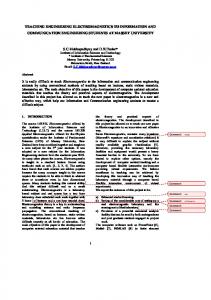
1. Manual Conceptual Design: Building of UML Class Diagrams which describe the structural aspects of database schemas. 2. Automatic Logical Design: Transformation of the UML Class Diagrams to Relational Schema without losing information. 3. Automatic Coding: Derivation of the DDL Code from the Relational Schema.
To achieve this goals, different components for the modeldriven development have to be implemented. Figure 1 illustrates the process of developing database schema, the correspondence to the MDA paradigm, and the most important building blocks to realize a model-driven, automatic approach. The development of those components is divided into three parts corresponding to the three exercises which have to be solved by the students in our course. In the following we describe each exercise in detail.
3.2
Lab1: Meta-Modeling
In order to translate UML Class Diagrams to Relational Schemas, a formal definition of both languages is indispensable. In Model Engineering, we use metamodel languages— comparable to meta languages like EBNF or XML schema— to define the modeling languages. The development of the abstract syntax of the modeling languages UML Class Diagram and Relational Schema is the first exercise in our course. The output of the exercise are metamodels for the simplified variant of the UML Class Diagram and for Relational Schema as well as automatically generated modeling editors supporting the definition of well-formed instances of both languages. The exercise is solved within the Eclipse Modeling Framework (EMF) which offers the metamodeling language Ecore to design metamodels and a component for code generation to automatically create modeling editors. The specification of the modeling languages is done in a byexample manner either in a textual or a graphical form (see the Appendix for examples). The students understand that metamodels may be used for both, textual and graphical languages. Those examples contain all language constructs which have to be included in the metamodel. Hence, the students have to derive the abstract syntax from the concrete syntax. This approach usually supports them to understand the different abstraction levels, because designing a language in this direction is often more natural than the other way around. Usually, the metamodels are not unique, as even the concepts of very restricted languages may be represented in different ways. In personal conversation with our staff members, different design decisions and metamodeling patterns are discussed.
3.3
Lab2: OCL and ATL
The first part of the second lab is to define static semantic constraints expressed in OCL for metamodels developed in Lab1. The second part is concerned with the development of a model-to-model transformation between the UML Class
Database Engineering Prozess Database Engineering Prozess Conceptual Design
Conceptual Schema
ME Lab 2008 ME Lab 2008
T Logical Design Logical Design
Logical Schema
DDL Code
2
3
MDE‐Process MDE Process Metamodel Modeling Language
PIM
M d ll2M d ll Modell2Modell Transformation Language Relational Metamodel M d l
Relational Schema
T Coding
UML Metamodel
UML Class Diagram
1
1
Metamodel Modeling Language d li
PSM
Modell2Code Transformation Language DDL Grammar
DDL
Code
1 …Lab 1 2 …Lab 2 3 …Lab 3
Figure 1: Illustration of the database engineering process Diagram metamodel and the relational metamodel. For ensuring a consistent evaluation, the students have to use the example metamodel solutions of Lab 1 given by the teachers. Exercise 1: OCL Constraints. For the UML metamodel, several constraints cannot be directly specified within the metamodel, thus, also inconsistent models may be created. The students have to specify a list of constraints given in natural language as OCL constraints. For testing the created constraints, two sample UML models are given. The first one represents a well-formed model for which no errors should be reported during validation, whereas the second one represents a faulty model which contains for each constraint a violation. For developing and testing the OCL constraints, the students use the Interactive OCL Console of Eclipse supporting sophisticated code completion which allows the incremental development of OCL statements. The complexity of the OCL constraints range from simple constraints such as a class needs a unique name to more complex constraints such as a class must not inherit directly or indirectly from itself. Exercise 2: UML 2 Relations Transformation. The students have to develop an ATL transformation for generating relational models from UML Class Diagrams. For this task, we provide again the metamodels for both languages as well as an input/output model pair. The transformation is correct when the given input model is exactly transformed into the given output model. Because there are several strategies to derive a relational model from a UML Class Diagram, we describe for each UML Class Diagram element how it should be represented in the relational model by giving a concrete example. Thereby, we start with simple one-to-one transformations, e.g., a class is transformed into a table, and then more complex strategies are described for bridging the gap between the object-oriented paradigm and the relational paradigm as enumerated in the following:
• n-to-m associations as join tables • ternary associations as join tables • attributes of association classes as columns of join tables • inheritance as delegation Strategy Description Example. In Figure 2, the strategy description for the resolution of n-to-m associations is shown. The descriptions always consist of three parts, namely the problem description (why a special transformation is necessary), a solution (how to represent the concept in the relational model), and a concrete example (taken out of the input/output model pair) describing the result of the transformation. Strategie g zur Auflösung g von N-M Assoziationen Problem: The relational model does not support N-to-M associations, because of the first normal form. … Solution: N-to-M associations may be presented by introducing additional Join Tables. … Example UML ToDoList
• multi-valued attributes as value tables
id1 (PK)
0..* consistsOf
T
ToDo
Table Constraints
JoinTable consistsOf JoinTable_consistsOf id1
0..*
id2
ToDo
PK: (id1, id2), FK: id1 REF T D Li (id1) O ToDoList(id1) On delete CASCADE, FK: id2 REF ToDo (id2) On delete CASCADE,,
id2 (PK)
Figure 2: Excerpt of the strategy description for representing n-to-m associations in relational models
3.4 • enumerations as domains plus check constraints
RELATIONAL ToDoList
Lab3: Code Generation
Since the automatic generation of executable source code by simply pushing a button is one vision of MDE, the last step of the lab focuses on code generation. For this, we are
applying the Xpand language of the oAW framework which is specialized on code generation based on EMF models. The lab consists of three parts.
4.
CONCLUSIONS
After solving the exercises in the labs and attending the lecture, the students should have obtained knowledge and experiences covering the following points:
Exercise 1: Relational to SQL. The first part comprises the generation of SQL-DDL code from the platform-specific relational model of Lab2. The required code generation templates are straightforward (mostly one-to-one transformation rules) to give the students a convenient entry in code generation.
• Design of modeling languages by defining metamodels • Development of rule-based model transformations • Development of template-base code generation scripts
Exercise 2: Class to Java. The second part omits the relational model and asks for an Xpand template for the transformation of the Class Diagram directly to annotated Java code. Current code generation techniques work quite well for generating skeletons out of static models. For demonstrating the usefulness of MDE in terms of reduced time of implementation, with guaranteed equality of code and model at the same time, generating skeletons is not enough for the ME lab. Instead, executable code should be generated which follows the semantics of the models. Therefore, we apply tagging techniques at the model level as well as at the code level. Special tags for model elements allow the modeler to define directly technical details in the models and enable the translation of the model’s semantics at the code level. Attribute-oriented programming is a tagging technique at code level. Program elements like classes, methods, and attributes can be marked to indicate that they keep some application-specific or domainspecific semantics. With the inclusion of JSR-1754 in Java 1.5 attribute-oriented programming is supported by annotations. For certain application-specific contexts annotations are provided by the Java EE framework. In our example, we make use of the annotations provided by the Java Persistence API (JPA)5 , which is included in the Java EE framework, to preserve the information of the model about unique values and primary key at code level, without implementing complex transformation code. The students must fully concentrate on developing the code generation, because the resulting Java code as well as JUnit tests for self-checking the code generation templates are given by the teachers. Exercise 3: Mapping Problems. In the third part, the students have to describe mapping problems consisting of concepts of the Class Diagram which are not properly transformed to the code level. This exercise reflects on Exercise 2 of this lab to understand which concepts of the Class Diagram are difficult to automatically transform to Java and were left out for the lab. For example, the xor constraint could be implemented in Java by using type variables or by more complex patterns. Although this exercise does not require the students to develop code generation templates, it is of special interest for the students. When examining which constraints are not guaranteed at the code level, the students realize the benefit of conceptual modeling because of its precise and concise representation possibilities for a particular domain.
4 5
http://jcp.org/en/jsr/detail?id=175 http://java.sun.com/javaee/technologies/persistence.jsp
• Development of a complete MDE environment based on Eclipse
On the way to reaching these goals we have made several observations and experiences on which we report in this section. Observations in the Lab. For the students, the model-tomodel transformation is the hardest part of the exercises as students are used to programming in an imperative manner. Consequently, they focus on imperative aspects when using hybrid languages, hence the solution gets sometimes more complex than they would have got when solved declaratively. On the other hand, the students are familiar with templatebased languages and hence they like the code generation exercise in general. Students also like the metamodeling examples, however, they first have to explore that Ecore-based metamodels have a concrete semantics (compared to using UML Class Diagrams in software engineering courses where they are mostly used as sketches) and that some guidelines have to be ensured for producing working editors out of the metamodels, such as the names of classes must be valid Java identifiers. Last year, we decided not to run a dedicated lab for developing a graphical editor with the GMF6 , because of the steep learning curve due to the size of this framework. However, we found out that students are really interested in developing graphical editors and that graphical editors are beneficial also for the other labs in general and in particular for testing model transformations. Therefore, we plan to provide again a dedicated lab for developing graphical editors, but this time we want to apply tools for developing graphical editors which build on top of GMF and hide some complexities of GMF such as GenGMF7 . What we often observed is that the students underestimate the necessary effort and start too late with the solution of the exercises. Especially making the tools run caused several problems in the past, when they started with only very little time left before the hand-in deadline. To overcome this problem, we introduced additional milestones where they have to show that they have some basic parts of the examples already solved and that they are able to deal with the tools. The exercises are solved in groups of three students and the results have to be presented to one academic staff member. The group size of three persons usually works out very well, because for the students it is still easy to organize such a small group, but they are not working alone on their exercises. 6 7
http://www.eclipse.org/gmf http://sourceforge.net/projects/gengmf
Development Infrastructure. The only complaints from students about the Model Engineering course concern the maturity of MDE technologies which are often not well documented and are sometimes not as user friendly as it is known from programming environments. However, with videos, tutorials, concrete suggestions, as well as forum support, we are trying to eliminate most issues about tooling problems in advance. Furthermore, it has to be noted that in the latest versions of the employed frameworks many issues have been eliminated. Currently, very different technologies and tools are used in the field of MDE, which do not integrate very smoothly. Partly, the students are faced with different terms and specifica of the tools which introduce unnecessary effort. To overcome this, we provide a dedicated Eclipse bundle which comprises all necessary plug-ins. But in the future, we would like to develop a dedicated model engineering platform for teaching purposes based on Eclipse which is reduced to the maximum of necessary operations for our courses and where consistent and complete tool support is provided from language engineering to transformation engineering. Furthermore, a text book covering the complete content of our lecture (including many illustrating examples) is not available. Currently, we are preparing a scriptum which will be provided to the students. Student Feedback. Especially for the lab, a complete running example is highly appreciated by the students. Those running examples must be chosen from a domain the students are familiar with like from the fields of data engineering or object-oriented modeling. When the students prepare solutions for the model transformations and code generation exercises, they like to see how executable applications may be generated from models. In this sense, the Model Engineering course closes the gap between previous programming courses and modeling courses which are not connected appropriately in the bachelor studies, but are rather seen as competitive by the students. Model Engineering helps the students recognize the benefits of modeling. Summary. With the rise of model-driven engineering, more and more dedicated modeling courses have been established at different universities. For example, in [3] has been reported that model-based approaches are the right mean for teaching the development of distributed systems. Another example is [4], where formal methods are taught with the help of models. While the former aims at applying a given modeling language to specify software systems with threelayer architectures, the latter takes advantages of formal verification for software models. However, our model engineering course is different to the aforementioned courses. We are focusing on teaching the students how to employ industrial-strength frameworks to develop their own modeldriven engineering environment which supports the generation of complete applications from platform independent models. The students have implemented in previous courses, e.g., in web engineering, data engineering, and software engineering, such applications by hand. After this course, the students realize the benefits of modeling in general and using a model-driven development approach in particular. This is reflected by the comments of the feedback sheets which the students have to fill out after completing the course.
In our course the students acquire a profound knowledge and hands-on experience concerning state-of-the-art Model Engineering techniques. Although the tool support is not mature what results in numerous pitfalls, in general the students appreciate to work with approaches directly stemming from ongoing research. For multiple students this course is the beginning of contributing in the area of Model Engineering in the form of seminar works, practicals, master theses and sometimes even of PhD theses.
5.
REFERENCES
[1] C. Batini, S. Ceri, and S. B. Navathe. Conceptual Database Design: An Entity-Relationship Approach. Addison Wesley, 1991. [2] M. Brandsteidl, M. Seidl, M. Wimmer, C. Huemer, and G. Kappel. Teaching Models @ BIG: How to Give 1000 Students an Understanding of the UML. In Promoting Software Modeling Through Active Education, Educators’ Symposium Models’08, pages 64–68. Warsaw University of Technology, 2008. [3] J. Cabot, F. Dur´ an, N. Moreno, A. Vallecillo, and J. R. Romero. From programming to modeling: our experience with a distributed software engineering course. In Proceedings of the 30th International Conference on Software Engineering (ICSE 2008), Leipzig, Germany, pages 749–758. ACM, 2008. [4] P. V. Gorp, H. Schippers, S. Demeyer, and D. Janssens. Transformation techniques can make students excited about formal methods. Information and Software Technology, 50(12):1295 – 1304, 2008. [5] M. Hitz, G. Kappel, E. Kapsammer, and W. Retschitzegger. UML @ Work. dpunkt, 2005. [6] OMG. MDA Guide Version 1.0.1. http://www.omg.org/docs/omg/03-06-01.pdf, June 2003. [7] T. Stahl and M. V¨ olter. Model-Driven Software Development. Wiley, 2007. [8] D. Steinberg, F. Budinsky, M. Paternostro, and E. Merks. Modellgetriebene Softwareentwicklung. Addison-Wesley, 2009. [9] J. Warmer and A. Kleppe. The Object Constraint Language: Getting Your Models Ready for MDA. Addison-Wesley, 2003.
APPENDIX Figure 3 shows an example describing a textual language (Relational Schema) and Figure 4 depicts a graphical language (simplified UML Class Diagram). Metamodels are proposed in Figures 6 and 5.
CREATE SCHEMA Administration; CREATE TABLE Employee ( oid INTEGER PRIMARY KEY, name UNIQUE VARCHAR(25), employed_since Funktion NOT NULL, boss INTEGER FOREIGN KEY(boss) REFERENCES Employee(oid) ); CREATE TABLE Person ( oid INTEGER PRIMARY KEY, name VARCHAR(30) ); CREATE TABLE Hobbys ( oid INTEGER NOT NULL, hobby VARCHAR(20), PRIMARY KEY(oid, hobby), FOREIGN KEY (oid) REFERENCES Person(oid) ON DELETE CASCADE ); CREATE DOMAIN Function AS VARCHAR(30) CHECK( VALUE IS IN {’Assistant’, ’Manager’} ); Figure 3: Example for the Relational Schema language
Figure 4: Example for the Class Diagram language
Figure 5: Metamodel of the Relational Schema language
Figure 6: Metamodel of the Class Diagram language