that the cache line size over 64 bytes has a good chance to let two basic blocks ... trace cache, instruction stream buffer, ILP, superscalar processor, x86 archi-.
JOURNAL OF INFORMATION SCIENCE AND ENGINEERING 26, 1273-1288 (2010)
The Basic Block Reassembling Instruction Stream Buffer with LWBTB for X86 ISA JIH-CHING CHIU, YU-LIANG CHOU AND TSENG-KUEI LIN Department of Electrical Engineering National Sun Yat-sen University Kaohsiung, 804 Taiwan The potential performance of superscalar processors can be exploited only when processor is fed with sufficient instruction bandwidth. The front-end units, the Instruction Stream Buffer (ISB) and the fetcher, are the key elements for achieving this goal. Current ISBs could not support instruction streaming beyond a basic block. In x86 processors, the split-line instruction problem worsens this situation. In this paper, we proposed a basic blocks reassembling ISB. By cooperating with the proposed LineWeighted Branch Target Buffer (LWBTB), the proposed ISB can predict upcoming branch information and reassemble current cache line together with the other cache line containing instructions for the next basic block. Therefore, the fetcher could fetch more instructions in a cycle with the assistance of the proposed ISB. Simulation results show that the cache line size over 64 bytes has a good chance to let two basic blocks present in a reassembled cache line and the fetch efficiency is about 90% as the fetch capacity is under 6. Keywords: trace cache, instruction stream buffer, ILP, superscalar processor, x86 architecture, multiple instruction fetch
1. INTRODUCTION High issue rate has been a crucial factor in superscalar processor design. This in turn requires high instruction fetch bandwidth. In most current processors, their Instruction Stream Buffers (ISBs) could not support instruction streaming beyond a basic block. The fetch rates will be constrained by the branch barriers. The trace cache studies [1-4], for example, focus on this point and suggest supporting super basic block instruction fetching. In the variable instruction length architectures, such as the x86 processors, the split-line instruction problem (one instruction is split across two separate cache lines) worsens this instruction-streaming problem. The x86 architectures are the dominant PC market standard in the personal computer marketplace. However, improving their performance is not an easy task. Current x86 architectures are implemented in the superscalar processing fashion, which requires the ability to run multiple instructions in a clock cycle. Being able to fetch sufficient instructions in a clock cycle is the first step to increase processor performance but is also the most difficult. To support a high instruction fetch bandwidth, some mechanisms such as the ISB in [5, 6] and the trace prediction in [7] are discussed. The ISB is used to maintain a small number of instructions which are most likely to be needed early with current fetchers limited to fetch one basic block or up to the maximum instruction fetch width per cycle [8]. In Wallace’s fetching model [9], a Received June 4, 2008 revised May 27 & August 17, 2009; accepted October 1, 2009. Communicated by Chung-Ping Chung.
1273
1274
JIH-CHING CHIU, YU-LIANG CHOU AND TSENG-KUEI LIN
block is defined as a group of sequential instructions. By increasing the block size, fetch performance will be increased. One way to fulfill this goal is to support super basic block fetching. The ISB must realign instructions in the predicted order, and then pass the instructions on to the fetcher [10]. Considering the many hurdles in fetching x86 instructions, we propose a design for a basic block reassembling ISB that can efficiently deal with branch taken and split-line instructions for CISC. Our previous work can be found in [11], it proposed the primary idea of basic block reassembling ISB but the hardware implementation of the ISB was not explained in detail. In this paper, we present a feasible hardware implementation method and reevaluate the performance of the ISB with the CPU SPEC2000int benchmarks [12]. We also propose a Line-Weighted Branch Target Buffer (LWBTB) to support future branch predictions.
2. THE CONCEPTS AND ALGORITHM OF PROPOSED INSTRUCTIONLINE-REASEMBLING MECHANISM 2.1 The Concepts of the Proposed Instruction-line-reassembling Mechanism Many hazards may exist in fetching x86 instructions. When a taken branch is encountered, the target instruction may not be fetched at the same time because of the branch instruction. And when a split-line instruction is encountered, the fetcher may need to access the instruction cache twice to get the full instruction. If these problems can be solved, more instructions can be fetched in a cycle. Thus the performance of the processor can be improved. To avoid these hazards, our ideas are described as follow: 1. Using a prefetch mechanism to prefetch useful cache lines into prefetch buffers. 2. To divide prefetch buffer entries into several equal parts. 3. To dynamically select and reassemble the equal parts into one buffer-entry-length piece according to BTB prediction. 4. To point each instructions in the prefetch buffer entry with instruction pointers. We call the reassembled parts as an instruction line. We first divide each prefetch buffer into two equal parts. Since the parts can be assembled dynamically, a target instruction can be placed in the same line with the corresponding branch instruction. Hence the taken branch problem is solved. The split-line instruction problem in CISC cases is solved by the same way; merging the parts dynamically makes it possible to place the sequential bytes of the requested instructions within the line. Thus, the fetcher can fetch beyond the limitation of branches and split-line instructions. 2.2 The Algorithm of the Proposed Instruction-line-reassembling Mechanism To avoid an interrupted instruction stream caused by branches and split-line instructions, we dynamically select two different half-line parts of the prefetch buffer entries to reassemble them in the desired order. The instruction-line-reassembling algorithm is given below:
THE BASIC BLOCK REASSEMBLING INSTRUCTION STREAM BUFFER
1275
Step 1: If the part containing the requested instruction does not exist in prefetch buffers, prefetch that cache line and exit; Step 2: Select the requested part as the lower-half part of the instruction line; Step 3: If there are no branches present from the requested instruction position to the end of that part, go to step 9; Step 4: If a branch instruction is encountered but split, go to step 9; Step 5: If the target instruction part is not in prefetch buffers, prefetch that target instruction cache line and exit; Step 6: If the branch and target are in the same part, go to step 9; Step 7: If the target instruction is split, exit; Step 8: Select target instruction part as the upper-half part of the instruction line and exit; Step 9: Select the lower-half part of the subsequent buffer line as the upper-half part of the instruction line if this lower-half part exists in prefetch buffers, otherwise prefetch that cache line and exit. Fig. 1 will show six cases of how to reassemble the instruction lines and we will explain each of these cases in turn. Fig. 1 (a) shows the Case 1, the sequential fetch situation. A small arrowhead is used to indicate the starting location of the requested instruction, and the shaded blocks are the blocks being selected to compose an instruction line. As Case 1A shown, since there are no branches present from the requested instruction position to the end of the part, the subsequent part is selected as the upper-half part of the instruction line. On the other hand, as Case 1B shown, if the subsequent part does not exist in prefetch buffers, it does not matter what the upper-half part of the instruction line is. Fig. 1 (b) shows the Case 2, the split branch situation. As Case 2A shown, there is a taken branch present and this branch instruction is a split-line instruction. The only part we can choose to reassemble is the subsequent part so that we can send the whole branch instruction to the fetcher after reassembling. On the other hand, as Case 2B shown, if the subsequent part is not in the buffers, we can still send the instruction line to the fetcher so as to trigger the prefetcher to prefetch the subsequent part, and then wait until the other portion of the branch instruction is obtained. Fig. 1 (c) shows the Case 3, the target miss situation. Although the branch instruction is not split, this branch’s target is not in the buffers. Thus the half-line part of the buffer entry containing the requested instruction is selected as the lower-half part of the instruction line. It does not matter what the upper-half part of the instruction line is Fig. 1 (d) shows the Case 4, branch and target (B&T) in the same part situation. Since the branch and its target are in the same half-line part of one buffer entry, we choose this half-line part as the lower-half part of the instruction line. And the subsequent half-line part can be selected as the upper-half part of the instruction line, if it exists. Fig. 1 (e) shows Case 5, the split target situation. The target instruction is in the buffers, but it is split across two half-line parts of one buffer entry. Because we can only select two half-line parts of different buffer entries to reassemble, we cannot send the branch and target instructions to the fetcher at the same time, even though we have some portions of the target instruction. Since the target instruction is already in the buffer, there is no need to prefetch it. The target line can only be sent to the fetcher in a whole
JIH-CHING CHIU, YU-LIANG CHOU AND TSENG-KUEI LIN
1276
piece the next time. Fig. 1 (f) shows Case 6, the target fetch situation. The branch and target instructions are not split across different half-line parts, so we simply select the half-line part containing the branch as the lower-half part of the instruction line and the half-line part containing the target as the upper-half part of the instruction line. (a) Case 1:sequential fetch Case 1A: subsequent part exists in buffer
(d) Case 4:B&T in the same part Case 1B: subsequent part does not exist
Case 4A: subsequent part exists in buffer B
T
B
…
…
…
…
B
T
T
B
T
(e) Case 5:split target
(b) Case 2:split branch Case 2A: subsequent part exists in buffer
Case 4B: subsequent part does not exist
Case 2B: subsequent part does not exist B
T …
…
…
B
B
invalid
(f) Case 6:target fetch
(c) Case 3:target miss
Prefetch buffer entry:
B
B
Instruction line: T …
…
B
B
invalid
T
lower-helf
upper-helf
Fig. 1. Scenarios of the proposed instruction-line-reassembling mechanism. LWBTB read address LWBTB
BTB BTB BTB BTB Banks BTB Banks Banks Banks Banks Pre-fetch addresses
Pre-fetch address to I-cache
Fetch Sequencer Pre-fetch buffer
Next PC
Reassembly Unit Next PC Generator Buffer line Reassembly Unit
Instruction Instruction Identifier Identifier0
Instruction identifier & pre-fetch buffer read address 2 Branch Predictions
Instruction Stream Buffer
…
Cache lines from I-cache
LWBTB Logic
Instruction identifier & pre-fetch buffer read address 1
Pointer Reorder Unit
Reassembled instruction line to fetcher Reordered pointers to fetcher
Fig. 2. The organizations of the proposed ISB.
3. THE HARDWARE DESIGNS OF THE PROPOSED ISB We will present the structure and functions of the components of proposed ISB in this section. Fig. 2 shows the architecture of proposed ISB. The proposed ISB consists of
THE BASIC BLOCK REASSEMBLING INSTRUCTION STREAM BUFFER
1277
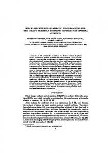
five major components: instruction identifier, prefetch buffers, LWBTB, fetch sequencer, and reassembly unit. In this paper, we use the instruction identifiers proposed in [13] to identify instruction length and to store the instruction pointers as superscalar instruction group indicators. The prefetch buffers can store the cache lines prefetched from the instruction cache (I-Cache). The size of each prefetch buffer entry is equal to the cache line size. Moreover, since the fetcher may not consume all the instructions provided in a reassembled line in a cycle, a small queue or a dual buffer might be needed to decouple the ISB and fetcher. 3.1 Designs of the LWBTB The BTB should be extended to provide enough reassembled information for proposed ISB. Thus we propose a new BTB architecture based on the EBTB architecture proposed in [14]. Similar to the EBTB architecture, the proposed BTB can provide the previous execution trace of a branch instruction. If there is a hit in the proposed BTB, two addresses are provided. The first address is the target of the first-encountered branch after current PC. The second address is the target or the fall-through address of the branch that is the first-encountered branch after the first target address. The proposed BTB can use the current fetch PC to explore the first-encountered branch in the near future. This is the key feature of our BTB different from the EBTB and the traditional BTB. Assuming that there are three successive branches: A, B, and C on the same cache line and the current PC is located between A and B. If we use the current PC to look up the traditional BTB or the EBTB, the search will be a miss under this situation because the current fetched instruction is not a branch. On the other hand, the search of proposed BTB will be a hit. The information of Branch B will be provided since proposed BTB will provide the information of the nearest branch after the current PC. In proposed BTB architecture, each branch on the cache line has its assigned weight according to its offset ahead from the current PC. The branch that has the smallest offset ahead from the current PC has the highest weight (the highest priority) and then will be selected by the proposed BTB. Thus we refer to the proposed BTB as the Line-Weighted BTB (LWBTB). Fig. 3 (a) shows the mechanism of how to save the branch information into LWBTB. In the right part of Fig. 3 (a), the organization of LWBTB is shown. The LWBTB consists of two components: the EBTB and an extended Branch Index Vector (BIV) table. The structure and mechanism of the EBTB are identical to [14]. A BIV table is introduced to cooperate with the EBTB to explore the upcoming branch after the current PC. In the BIV table, each entry of the table records a Branch Index Vector (BIV), a list of bits that indicates the positions of the branches on a dedicated cache line. By these BIVs, the LWBTB can rapidly find the nearest branch after the current PC. In the left part of Fig. 3 (a), a binary-tree-like structure gives an abstract representation of a program execution flow. Each square stands for a basic block. Inside each square, “branchX” stands for the last control transfer instruction of that basic block, and “inst n” stands for the target instruction of the last branch in previous basic block. If branchA is taken, the branchA’s information will be recorded in the LWBTB. When recording the branchA’s information into LWBTB, two actions will be performed simultaneously. One action is that a corresponding entry of the BIV table will be indexed by the
JIH-CHING CHIU, YU-LIANG CHOU AND TSENG-KUEI LIN
1278
address of branchA and then this entry will be updated. The other action is that a corresponding entry of the EBTB will be indexed by the address of branchA and then the address of inst 0 will be stored into the “target addr_1” field of this entry. As the instruction stream flows ahead, the branchB will be encountered. If the branchB is not taken, the address of inst2, the fall-through instruction of branchB, will be saved into the “target addr_2” field of the branchA’s entry. If the branchB is taken, not only the branchB’s corresponding entries of the BIV table and the EBTB need to be recorded but also the address of inst1, the target instruction of branchB, need to be saved into the “target addr_2” field of the branchA’s entry. This maintaining mechanism can be realized by using a two-entry FIFO queue and the detail implementation can be found in [14]. (a)
LWBTB Branch Index Vector (BIV) table Index into branchA not taken
line
1
1
taken
EBTB
branchB Taken? not taken
inst 2
l
o line offsethistorytaken addr_1taken addr_2 line offsethistorytaken addr_1taken addr_2 line offsethistorytaken addr_1taken addr_2 line offsethistorytaken addr_1taken addr_2
=
inst 0 branchC
1
taken inst 1
Branch address
(b)
PC ( instruction Cache line size fetch address): line offset Branch address
=
=
=
Branch index vector 1 1 1 En En En En
line offset history target addr_1 target addr_2 Selector Hit ?
Mux Selected target addr_1 and target addr_2
(a) Maintaining mechanism of the LWBTB. (b) An example of the searching mechanism of the LWBTB. Fig. 3. Organizations of the LWBTB.
Fig. 3 (b) shows an example of the searching mechanism of the LWBTB. In this example, we assume the information of each branch (the branch address, history, target_1 address, and target_2 address) can be saved into all the entries of the LWBTB. For determining whether the branches and the current fetched instruction are on the same cache line, each PC (instruction fetch address) can be viewed as consisting of two fields, line and offset fields. The offset field, the least significant o bits, identifies a specific position of a cache line. The line field, the remaining l bits, specifies the lines of the cache. The symbol “ ” stands for a comparator. By simultaneously comparing the line field of PC with the line fields of every LWBTB entries, we can determine which branches and the current fetched instruction are on the same cache line. When finding the branches on the same cache line requested by current PC, we also need to search the nearest branch after the current PC. We use the line field of the PC to obtain the corresponding BIV from the BIV table. The symbol “ ” stands for an encoder. This encoder can rapidly generate the offset from current PC to a branch address kept in a LWBTB entry according to three inputs: the offset of PC, the offset of a branch address, and the BIV. Finally the selector will select the corresponding target addresses and generate the hit signal according to the offsets generated by the encoders and the results generated by the comparators. To reduce the complexity of the large-scale LWBTB, we divide the LWBTB into M banks (each bank has N entries) and we limit each bank can only store one of the branches on the same cache line; that is, LWBTB can keep up to M branches on the same
THE BASIC BLOCK REASSEMBLING INSTRUCTION STREAM BUFFER
1279
cache line. We separate branches into three types: always taken branch and conditional branch, and call return branch. We use a conditional branch predictor to predict the always taken branch, conditional branch. We also use the return address predictor to predict call return branch. Different strategies may be used for maintaining the information stored in LWBTB, we consider three placement rules: arbitrarily, fixed bank, and Nclusters rules for LWBTB to store branch information: 1. Arbitrary placement rule: the branch can be placed in an arbitrary bank according to the LRU (Least Recently Used) algorithm, and hence the branch will be placed into the least used bank. This rule can increase the utility rate of each bank, but the hardware for searching the branches will become more complex. 2. Fixed bank placement rule: the branch has its own specific bank for placement. The hardware for searching the branch will become simpler but the hit rate of LWBTB will drop. 3. N-clusters placement rule: it will combine the first and second rules described above to take advantage of both rules. The high bits of branch address offset will be decoded in order to decide into which bank cluster the branch will be placed. After choosing the placing bank cluster, we place the branch into the least used bank according to the LRU algorithm. Each bank in LWBTB is like the cache and hence each bank structure can also be configured as direct mapped, set associative, and fully associative. Different placement rules lead to different selector hardware costs. Under the same performance, the simple architecture may not have lower hardware costs. This is because the complex architecture can use fewer banks to obtain the same performance. In section 4.1, we will simulate different LWBTB architectures to estimate which architecture is a good performance choice. 3.2 Designs of the Fetch Sequencer The fetch sequencer will guide the direction of the instruction stream according to the branch information preserved by it. As Fig. 4 shown, it can generate the access addresses of the LWBTB, instruction identifier and prefetch buffer. The LWBTB can provide the information of two successive branches, and this information can be saved in the fetch sequencer as a guide for directing the instruction stream. The fetch sequencer compares the address of the branch whose information is preserved by it with the current PC to check whether this branch was fetched in the previous cycle or not. If the branch was fetched, the branch information will be cleared or updated. In each cycle, fetch sequencer generates the access addresses of the LWBTB, instruction identifier and prefetch buffer. In the first half cycle, the read address of LWBTB and first read addresses of instruction identifier and prefetch buffer are sent. In the second half cycle, the second read addresses of instruction identifier and prefetch buffer are sent. If the instruction identifier and prefetch buffer are both hit, we can obtain the reassembled buffer line and reordered instruction pointers in the end of this cycle. Also, in the end of the cycle, the information of two branches is also obtained from the LWBTB. Fetch sequencer will use this information to generate the addresses for the next cycle.
1280
JIH-CHING CHIU, YU-LIANG CHOU AND TSENG-KUEI LIN
LWBTB
Cycle1
Branch A (first branch after PC1) Branch B (first branch after the target address of branch A) BTB BTB Logic Logic
BTB BTB Bank Bank
Pre-fetch Buffer
PC1 Fetch Sequencer PC1
PC1
Empty
A
The address of the next sequential buffer line
B C
LWBTB
Cycle2
Reassembled Line A
D
subsequent part
Branch C (first branch after the target address of branch B) Branch D (first branch after the target address of branch C) BTB BTB Logic Logic
BTB BTB Bank Bank
Pre-fetch Buffer
Target address of branch B Fetch Sequencer PC2
PC2
Branch B
A B C D
Target address of branch B
Reassembled Line B
C
Fig. 4. The mechanism of the proposed ISB.
Fig. 4 shows an example of how the fetch sequencer directs the instruction stream. In cycle 1, we assume that there is no branch information in the fetch sequencer. The fetch sequencer generates two read addresses, the PC1 and the starting address of the next sequential buffer entry after PC1, to the prefetch buffers. If the prefetch buffer is hit, two corresponding buffer entries will be sent to the reassembly unit. The half-line part of the buffer entry containing the requested instruction will be selected as the lower-half part of the reassembled line. The lower half-line part of the next sequential buffer entry after PC1 will be selected as the upper-half part of the reassembled line. In cycle 1, the fetch sequencer also uses PC1 to access LWBTB to get the information of two successive branches for next cycle, branch A and branch B in this example. If branch A is not fetched by fetcher in this cycle, its information will be saved in the fetch sequencer in the next cycle, otherwise branch B’s information will be saved and the next PC will be the target address of branch A. Both target addresses of these two branches can be the prefetch addresses of the prefetch buffer to prefetch the cache line that may be used in the near future. In cycle 2, we assume branch A is the fetched instruction in cycle 1 and then the information of branch B is saved in the fetch sequencer with PC2 as the target address of branch A. The fetch sequencer generates two read addresses, PC2 and target address of branch B, to the prefetch buffers. If the prefetch buffer is hit, two corresponding buffer entries will be sent to the reassembly unit. The half-line part of the buffer entry containing branch B will be selected as the lower-half part of the reassembled line. The half-line part of the buffer entry containing branch C will be selected as the upper-half part of the reassembled line. The fetch sequencer will use the target address of branch B to access the LWBTB to get the information of branch C and branch D. If branch B is not fetched in this cycle, the information of branch C and branch D will be abandoned but the target addresses of these two branches can be the prefetch addresses for prefetching.
THE BASIC BLOCK REASSEMBLING INSTRUCTION STREAM BUFFER
1281
3.3 Designs of the Reassembly Unit The Reassembly unit consists of three major components: the buffer line reassembly unit, the pointer reorder unit, and the next PC generator. The buffer line reassembly unit can reassemble two buffer lines into an instruction line according to the algorithm discussed in section 2. The next PC generator can generate the next PC according to the number of instructions fetched in this cycle and the branch information in the fetch sequencer. Since we reassemble the cache lines into an instruction line for fetcher, the instructions pointers that indicate the instruction length on a cache line also need to be reordered. The pointer reorder unit is responsible for this work and provides reordered instruction pointers for the fetcher. We use the two instruction identifiers to obtain the two pointer groups.
4. SIMULATION RESULTS To evaluate the performance of the proposed ISB, we build a trace-driven simulator. In the simulations, ten SPECint2000 benchmarks [12], the bzip2, crafty, gap, gcc, gzip, mcf, parser, twolf, vortex, and vpr are used. Ten benchmarks are compiled by gcc and executed on an x86 machine with Linux OS. When a benchmark is executed, we use the system call “ptrace” to get the traces and save them in files. Then, we feed the trace files and a group of simulation parameters to the simulator. After completing the execution of the trace-driven simulator, the simulation results are obtained. All the results presented in the later subsections are the average of ten benchmark results. By analyzing the instructions of the ten CPU SPEC2000int benchmarks, we find that the most frequently appearing lengths of the x86 instructions are 2 or 3 bytes and the average basic block size is 6 instructions. Thus the length of the sequential fetchable instructions is 12-18 bytes. This is an important simulation result for our later simulations. 4.1 LWBTB Simulations In this section, we change the number of the LWBTB banks and its entries to simulate the average miss rate of ten benchmarks. The branch predictor used for the simulation is GAg architecture (Two-Level Adaptive Branch Prediction Using a Global History Register and a Global Pattern History Table) mentioned in [15]. The strategy used to identify the current branch is a Global History Predictor with an Index Sharing Strategy (a strategy of exclusive ORing branch address and global history register) mentioned in [16]. We assume that the return address predictor is sufficiently large (i.e., as large as the maximum call depth). The remaining simulation parameters are according to AMD Athlon processor features [17]: • Global Pattern History Table has 16384 entries. • Global History Register is 14 bits. • Cache line size is 64 bytes.
JIH-CHING CHIU, YU-LIANG CHOU AND TSENG-KUEI LIN
1282
(b)
Miss Rate(%)
Miss Rate(%)
(a) 20 15 10 5 0
20 15 10 5 0 512
4
8
16
32
Number of LWBTB's Bank
Fixed bank placement rule Arbitrary placement rule
2-clusters placement rule
1024
2048
4096
Number of LWBTB's Entry Direct Mapped Bank Structure 2-Way Set Associative Bank Structure
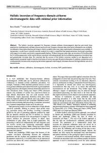
(a) The relationship between the banks and (b) The relationship between the entries and the different placement rules. different bank structure. Fig. 5. The simulation results of the LWBTB.
In Fig. 5 (a), we simulated the relationship between the banks and the different placement rules. The simulation parameters of LWBTB are as below: • Number of Banks: 4, 8, 16, and 32. • Placement rules: Fixed bank, 2-clusters, and Arbitrarily placement rule. • Bank structure: Direct mapped structure. • Total entries: 512. The x-axis represents the number of banks of the LWBTB, and the y-axis represents the miss rate. We observe that the miss rate of 4 banks for the LWBTB is much higher than for other LWBTB bank numbers because the cache line size is 64 bytes and the length of the sequential fetchable instructions is 12-18 bytes; that is, there are an average 5.3-3.5 branches in a cache line. But, under the cost effective design consideration mentioned in section 3.1, the 4 banks LWBTB can only handle 4 branches on the same cache line. Thus 4 banks LWBTB could not keep all branches on the same cache line and may incur the high miss rate. Moreover, we observe that the 8 banks LWBTB is a good choice as the placement rule of LWBTB is a 2-cluster placement rule or an arbitrary placement rule. When the placement rule of LWBTB is a fixed bank placement rule, the 16 banks LWBTB is a good choice. In Fig. 5 (b), we simulated the relationship between the entries and different bank structure. The simulation parameters of LWBTB are as below: • Bank number: 4. • Placement rules: Arbitrary placement rule. • Bank structure: Direct mapped structure and 2-way set associative structure. • Total entries: 512, 1024, 2048, and 4096. The x-axis represents the number of entries of LWBTB, and the y-axis represents the average miss rate of ten benchmarks. Although the 4096 entries LWBTB with a 2-Way set associative bank structure has the lowest miss rate, its hardware cost is the highest in the simulation. Considering the cost-effectiveness, the 2048 entries LWBTB with a 2-Way set associative bank structure is a good choice; its miss rate is slightly higher than the lowest, but its total entries are the half of entries of the 4096 entries LWBTB with a 2-Way set associative bank structure.
THE BASIC BLOCK REASSEMBLING INSTRUCTION STREAM BUFFER
1283
4.2 Proposed ISB Simulations In this section, we will simulate the ability of the proposed ISB to improve frontend performance. We will simulate the fetch rate with different fetcher capacities and cache line sizes to estimate the performance. The simulation assumptions are as below: • Prefetch buffer hit rate 100%. • LWBTB hit rate 100% and the predictions are always accurate. • Instruction identifier hit rate 100%. • The back-end issue rate is assumed as infinity. (a)
2 parts reassembled scheme
Y-axis 12 11 10
Traditional fetch scheme
9 8 7
IPC
6
(b)
4 3 2 1
is
0 5122 56 28 1 64 2 3 512
Cache Line Size
8 6 4 2 5 61 2 8 4 6 32
2
10
12
14
16
Z-axis
Fetch Capacity (instructions)
(a) The IPCs of traditional fetch scheme and 2 part reassembled scheme0.
IP C
5
x X-a
Cache Line Size:64 Bytes
5.421989 4.5 4 3.5 3 2.5 2 1.5 1 0.5 0 2
3
4
5
6
7
8
9
10
Fetch Capacity(instructions) I-Cache:1 Read Port Buffer:2 Line Buffer:8 Line
I-Cache:2 Read Port Buffer:4 Line
(b) The cache line fetching scheme analysis.
Fig. 6. The simulation results of the proposed ISB.
The can bars in Fig. 6 (a) show the average ten benchmarks’ IPCs (instructions per cycle) of different cache line sizes with traditional fetch scheme. The Z-axis represents the fetch capacities from 2 to 16, and the Y-axis represents the IPC. The five can bars represent five different cache line sizes: 32, 64, 128, 256, 512 bytes. In each different fetch capacity simulation result, more instructions can be fetched per cycle when the cache line size is larger. However, when cache line size is over 128 bytes, we will get poor fetch efficiency (IPC divided by fetch capacity) if we attempt to obtain higher IPC by further enlarging the fetch capacity. The cube bars in Fig. 6 (a) show the average ten benchmarks’ IPCs of different cache line sizes with the 2 part reassembled scheme. When the cache line size is over 64 bytes, the IPCs of proposed scheme are larger than those of the traditional fetch scheme. When the fetch capacity is under 6, the fetch efficiency is about 90% expect for the result of 32 bytes cache line simulation. Because the length of sequential fetchable instructions is 12-18 bytes mentioned in the beginning of this section, there is a good chance of having two basic blocks on the reassembled instruction line as cache line size is over 64. In the 32-byte cache line size simulation, the half cache line size is 16 that is approximate
1284
JIH-CHING CHIU, YU-LIANG CHOU AND TSENG-KUEI LIN
the length of the sequential fetchable instructions. Hence the reassembled scheme can not gain any advantages with the 32bytes cache line size. Finally, we consider the memory hierarchy delays in the simulation. The memory module parameters are referenced from the memory system of AMD Athlon processor: • 64K two-way set associative L1 I-cache. • L1 I-cache access takes 3 cycles, 100% hit rate. Since the 64K bytes L1 I-cache is large enough to keep all instructions of a single benchmark program, the miss rate of L1 I-cache might be very small when executing a single benchmark. That is, L2 cache might be rarely accessed when executing a single benchmark. Thus we assume that the L1 I-cache’s hit rate is 100%. According to the memory read cycle of CACTI3.2 [18], memory read cycle module program, and the memory frequency of AMD Athlon processor, we assume the read cycles of L1 I-cache with one read port are 3 cycles and the read cycles of L1 I-cache with two read ports are 4 cycles. The summaries of simulation parameters are as follows: • Cache line size is 64 bytes. • Buffer entry size is 64 bytes. • LWBTB hit rate 100% with the predictions always accurate. • Instruction Pointer table hit rate 100%. • L1 I-cache hit rate is 100%. • The back-end issue rate is assumed as infinity. • If the hardware uses a prefetch buffer, it will take 3 cycles to obtain one cache line. • If the hardware uses one read port L1 I-cache, it will take 3 cycles to obtain one cache line. • If the hardware uses a two read port L1 I-cache, it will take 4 cycles to obtain one cache line. Fig. 6 (b) shows the results with different memory fetch architecture as well as showing the relation between fetch capacity and IPC. When the fetch capacity is greater then 6, the performance of hardware with a two read port cache is better than the hardware with a 2 entries prefetch buffer. The reason is that the miss rate of a 2 entries prefetch buffer is high. The performance of hardware with more than 4 entries prefetch buffer is less affected by the access delay. Hence we suggest the prefetch buffer have at least 4 entries. Even when we add the memory access delay factors, the fetch efficiency is still held at 70% when a 4 entries prefetch buffer with 4 fetch capacities hardware or 8 entries prefetch buffer with 5 fetch capacities hardware is adopted. This simulation results reveal that the proposed ISB can increase the instruction fetch bandwidth efficiently.
5. RELATED WORK Previous works have proposed some fetch architectures capable of fetching multiple non-sequential basic blocks in a single cycle. Yeh et al. [19] introduced the Branch Address Cache (BAC) for supporting fetch addresses of predicted blocks and an extended two-level branch predictor that can predict multiple branches per cycle. Similarly, Conte
THE BASIC BLOCK REASSEMBLING INSTRUCTION STREAM BUFFER
1285
et al. [20] proposed the collapsing buffer as a mechanism to fetch basic blocks simultaneously. Both of these two front-end architectures require multiple read ports to the I-cache, a complex branch predictor, and a complicated realignment network to join the fetched blocks. Moreover, both front-end architectures are not suitable for the x86 architecture. The x86 variable-length ISA complicates the design of realignment network. On the other hand, our method dose not has the drawbacks described above. Since the LWBTB can forecast future branch and enable the fetch sequencer to generate the corresponding prefetch addresses for the prefetch buffers as early as possible, the I-cache bandwidth demand for our front-end architecture is low and the I-cache does not need any modification. Since each entry of the LWBTB stores the previous execution trace of two successive branches, we need not to predict whether the second branch is taken or not. A traditional branch predictor is sufficient for our method. Since we simply select two half-line parts of the prefetch buffers to reassemble rather than collecting the non-sequential instructions from different cache lines, the reassembling hardware is simple. Recently, Reinman et al. [21, 22] proposed the fetch target queue (FTQ) to decouple the dynamic branch prediction mechanism from the instruction cache access. Since this architecture efficiently decouples branch prediction from the memory access, the high bandwidth I-cache is avoided. The fetch target buffer (FTB) is also proposed by Reinman et al. The FTB extends the BTB by allowing the storage of variable length fetch blocks. A fetch block is a sequence of instructions starting at a branch target, and ending at a strongly biased taken branch. Therefore, a fetch block may contain multiple basic blocks, and multiple branches, as long as all the intermediate branches are strongly biased nottaken. When the fetcher fetches instruction from a fetch block, such not-taken branches can be easily predicted by simply ignoring them. Based on [21, 22], the stream fetch architecture [23, 24] was proposed. The stream fetch architecture is the use of a specialized branch predictor (the stream predictor) which provides streams level sequencing. Each prediction contains information about a whole instruction, possibly containing multiple basic blocks. Different from the fetch block, a stream is a sequential run of instructions, from the target of a taken branch to the next taken branch. Therefore a stream may contain more multiple basic blocks than a fetch block. In [25, 26], the multiple stream predictor is proposed for the stream fetch architecture to make streams as long as possible to hide the prediction table access delay without increasing the fetch engine complexity. In conclusion, both architectures can fetch multiple basic blocks in a single cycle only when the execution path of branches is proceeding according to their desire (the path starts at a branch target, goes through many not-taken intermediate branches, and then ends at a taken branch). An interrupted instruction stream will be encountered under two situations. First is that a stream or a fetch block is split across two cache line. Second is that the fetch of the architecture across two successive streams or fetch blocks. On the other hand, basing on the trace predictions of LWBTB and the reassembling mechanism our architecture can not only do the same works that [21-26] can do but also deal with the above situations of interrupting the instruction stream. Another front-end architecture, the trace cache [1-4] recently implemented in the Intel Pentium4 processor, provides high fetch bandwidth by reusing dynamic instruction traces stored in a special purpose cache. Since these traces may contain multiple basic blocks, and several branches, regardless of their being taken or not, the trace cache avoids the realignment network required by mechanisms mentioned above. However, the
1286
JIH-CHING CHIU, YU-LIANG CHOU AND TSENG-KUEI LIN
trace-rebuilding mechanism becomes a performance bottleneck during trace cache misses. To resolve this, [27] proposed a mechanism for combining a trace cache with conventional branch-predictions architecture to help reduce the latency and hardware requirements of the trace-rebuilding mechanism. The main disadvantage of the trace cache is its high complexity. It needs a dynamic mechanism for building traces and then stores the trace into a special purpose cache. This architecture has turned out to be less efficient than expected and is no longer used in new designs of current Intel processors [28].
6. CONCLUSIONS In this paper, we deal with the intrinsic difficulty of x86 superscalar architectures by introducing an improved instruction stream buffer design. Although current x86 superscalar microprocessors employ different kinds of instruction stream buffers, all of them are constrained by the one basic block limitation. The goal of this research is to place instructions across branch boundaries or to split two cache lines in the fetch buffer. This goal is realized by dividing each prefetched instruction lines into two half-line parts, and by dynamically selecting and reassembling two of these parts into the fetch buffer according to the LWBTB prediction information. Simulation results suggest that the LWBTB with these parameters: 2-clusters placement rule, 8 banks, 2-way set associative bank structure, and 2048 entries is a good choice. From the ISB simulation results, the cache line size over 64 bytes has a good chance to let two basic blocks on the reassembled instruction line and when the fetch capacity is under 6, the fetch efficiency is about 90%. We suggest the prefetch buffer have at least 4 entries and use the predicted target address of LWBTB to prefetch cache lines. When the memory access delay factors are considered, the fetch efficiency is still held at 70% as a 4 entries prefetch buffer with 4 fetch capacities hardware or an 8 entries prefetch buffer with a 5 fetch capacities hardware are adopted. In the future, an instruction cache line can be divided into finer segments for more flexible fetch buffer reassembling. And this direction will certainly be a key enhancement for x86 microprocessor designs.
REFERENCES 1. S. J. Patel, D. H. Friendly, and Y. N. Patt, “Evaluation of design options for the trace cache fetch mechanism,” IEEE Transactions on Computers, Vol. 48, 1999, pp. 193204. 2. E. Rotenberg, S. Bennett, and J. E. Smith, “Trace cache: A low latency approach to high band-width instruction fetching,” in Proceedings of the 29th International Symposium on Microarchitecture, 1996, pp. 24-34. 3. S. Jourdan, L. Rappoport, Y. Almog, M. Erez, A. Yoaz, and R. Ronen, “eXtended block cache,” in Proceedings of the 6th International Symposium on High-Performance Computer Architecture, 2000, pp. 61-70. 4. B. Black, B. Rychlik, and J. P. Shen, “The block-based trace cache,” in Proceedings of the 26th International Symposium on Computer Architecture, 1999, pp. 196-207.
THE BASIC BLOCK REASSEMBLING INSTRUCTION STREAM BUFFER
1287
5. M. Slater, “AMD’s K5 designed to outrun pentium: four-issues out-of-order processor is first member of K86 family,” Microprocessor Report, Vol. 8, 1994, pp. 1-11. 6. L. Gwennap, “Intel’s P6 uses decoupled superscalar design,” Microprocessor Report, Vol. 9, 1995, pp. 9-15. 7. A. Siamak, S. Howard, and D. Sreeram, “An architecture for high instruction level parallelism,” in Proceedings of the 28th Annual Hawaii International Conference on System Sciences, 1995, pp. 153-162. 8. J. C. Chiu, J. N. Yang, R. M Shiu, and C. P Chung, “A proposed fetch rule model for fetching multi-ple x86 instructions,” in Proceedings of International Conference on Computer Systems Technology for Industrial Applications, 1998, pp. 31-36. 9. S. Wallace and N. Bagherzaqeh, “Modeled and measured instruction fetching performance for superscalar microprocessors,” IEEE Transactions on Parallel and Distributed Systems, Vol. 9, 1998, pp. 570-578. 10. G. Hinton, D. Sager, M. Upton, D. Dogs, D. Carmean, A. Kyker, and P. Roussel, “The microarchitecture of pentium 4 processor,” Intel Technology Journal, 2001. 11. J. C. Chiu, I. H. Huang, and C. P. Chung, “Design of instruction stream buffer with trace support for X86 processors,” in Proceedings IEEE International Conference on Computer Design, 2000, pp. 294-299. 12. Standard Performance Evaluation Corporation, http://www.spec.org/spec/cotact.html. 13. J. C. Chiu and C. P. Chung, “High-bandwidth x86 instruction fetching based on instruction pointer table,” in IEE Proceedings of the Computer and Digital Techniques, Vol. 148, 2001, pp. 113-118. 14. J. C. Chiu, R. M. Shiu, S. A. Chi, and C. P. Chung, “Instruction cache prefetching directed by branch prediction,” in IEE Proceedings of the Computer and Digital Techniques, Vol. 146, 1999, pp. 241-246. 15. T. Y. Yeh and Y. N. Patt, “Alternative implementations of two-level adaptive branch prediction,” in Proceedings of the 19th Annual International Symposium on Computer Architecture, 1992, pp. 124-134. 16. S. McFarlin, “Combining branch predictors,” WRL Technical Report TN-36, Digital Equipment Corp., 1993. 17. AMD Corp., “Software optimization guide for AMD Athlon 64 and AMD opteron,” Technical Document, 2004. 18. S. J. E. Wilton and N. P. Jouppi, “An enhanced access and cycle time model for on-chip caches,” WRL Technical Report 93/5, Digital Equipment Corp., 1994. 19. T. Y. Yeh, D. T. Marr, and Y. N. Patt, “Increasing the instruction fetch rate via multiple branch prediction and a branch address cache,” in Proceedings of the 7th International Conference on Super-Computing, 1993, pp. 67-76. 20. T. Conte, K. Menezes, P. Mills, and B. Patell, “Optimization of instruction fetch mechanism for high issue rates,” in Proceedings of the 22nd Annual International Symposium on Computer Architecture, 1995, pp. 333-344. 21. G. Reinman, T. Austin, and B. Calder, “A scalable front-end architecture for fast instruction delivery,” in Proceedings of the 26th International Symposium on Computer Architecture, 1999, pp. 234-245. 22. G. Reinman, B. Calder, and T. Austin, “Optimizations enabled by a decoupled frontend architecture,” IEEE Transactions on Computers, Vol. 50, 2001, pp. 338-355. 23. A. Ramirez, O. J. Santana, J. L. Larriba-Pey, and M. Valero, “Fetching instruction
1288
24. 25. 26. 27. 28.
JIH-CHING CHIU, YU-LIANG CHOU AND TSENG-KUEI LIN
streams,” in Proceedings of the 35th international Symposium on Microarchitecture, 2002, pp. 371-382. O. J. Santana, A. Ramirez, J. L. Larriba-Pey, and M. Valero, “A low-complexity fetch architecture for high-performance superscalar processors,” ACM Transactions on Architecture and Code Optimization, Vol. 1, 2004, pp. 220-245. O. J. Santana, A. Ramirez, and M. Valero, “Multiple stream prediction,” Lecture Notes in Computer Science, Vol. 4759, 2008, pp. 1-16. O. J. Santana, A. Ramirez, and M. Valero, “Enlarging instruction streams,” IEEE Transactions on Computers, Vol. 56, 2007, pp. 1342-1357. G. Reinman and G. Pitigoi-Aron, “Trace cache miss tolerance for deeply pipelined superscalar processors,” in IEE Proceedings of the Computer and Digital Techniques, Vol. 153, 2006, pp. 355-361. A. Fog, “The microarchitecture of Intel and AMD CPU’s: An optimization guide for assembly programmers and compiler makers,” Copenhagen University College of Engineering, 2009, http://www.agner.org/optimize/. Jih-Ching Chiu (邱日清) received the B.S. and M.S. degrees in Electrical Engineering from National Sun Yat-sen University and National Cheng Kung University, Taiwan, in 1984 and 1986, respectively. He received the Ph.D. degree in Computer Science and Information Engineering from National Chiao Tung University, Taiwan, in 2002. In 1989 he joined the National Sun Yat-sen University, Taiwan, and is presently Assistant Professor of Electrical Engineering. His research interests are in the areas of ILP CPU design, computer system integration, and embedded system design.
Yu-Liang Chou (周育樑) received the B.S. and M.S. degrees in Electrical Engineering from National Sun Yat-sen University in 2003 and 2005, respectively. Currently, he is pursuing the Ph.D. degree in Electrical Engineering at National Sun Yat-sen University. His current research interests include computer architecture, x86 architecture, parallel processing, and reconfigurable system designs.
Tseng-Kuei Lin (林增奎) received the B.S. and M.S. degrees in Elctrical Engineering from National Sun Yat-sen University in 2003 and 2005, respectively. His current research interests include computer architecture design, x86 architecture, and computer system designs.