JOURNAL OF APPLIED PHYSICS 107, 103910 共2010兲
The demagnetizing field of a nonuniform rectangular prism A. Smith,1 K. K. Nielsen,1,2,a兲 D. V. Christensen,1,3 C. R. H. Bahl,1 R. Bjørk,1 and J. Hattel2 1
Fuel Cells and Solid State Chemistry Division, Risø National Laboratory for Sustainable Energy, Technical University of Denmark, Frederiksborgvej 399, DK-4000 Roskilde, Denmark 2 Department of Mechanical Engineering, Technical University of Denmark, Building 425, Niels Koppels Alle, DK-2800 Kongens Lyngby, Denmark 3 The Niels Bohr Institute, University of Copenhagen, Blegdamsvej 17, DK-2100 Copenhagen, Denmark
共Received 8 February 2010; accepted 12 March 2010; published online 20 May 2010兲 The effect of demagnetization on the magnetic properties of a rectangular ferromagnetic prism under nonuniform conditions is investigated. A numerical model for solving the spatially varying internal magnetic field is developed, validated, and applied to relevant cases. The demagnetizing field is solved by an analytical calculation and the coupling between applied field, the demagnetization tensor field, and spatially varying temperature is solved through iteration. We show that the demagnetizing field is of great importance in many cases and that it is necessary to take into account the nonuniformity of the internal field, especially for nonconstant temperature distributions and composite magnetic materials. © 2010 American Institute of Physics. 关doi:10.1063/1.3385387兴 I. INTRODUCTION
The importance of demagnetization for the properties of a magnetic body has long been recognized. The long-range nature of the dipolar force acting between individual magnetic moments will give rise to a demagnetizing field inside the body and can give rise to shape dependence of the thermodynamic properties, e.g., the heat capacity, of the body.1 Only in uniform ellipsoidal samples 共and a few other limiting cases such as an infinite sheet or an infinite cylinder兲 is the demagnetizing field uniform. Even in these cases, calculations of the demagnetizing field can be quite involved.2 The results can be expressed in terms of a demagnetization tensor N H = Happl − N · M,
共1兲
where H is the total internal magnetic field, Happl is the applied magnetic field, and M is the constant magnetization. The demagnetization tensor is symmetrical and has a trace equal to one. If the coordinate axes are chosen to coincide with the principal axes of the ellipsoid, the demagnetization tensor becomes diagonal. Thus, the demagnetizing field is determined by three quantities Nxx, Nyy, and Nzz whose sum is unity. When both the applied field and M are along a principal axis, Eq. 共1兲 becomes the scalar equation H = Happl − NM ,
共2兲
where N is the relevant demagnetization factor. This equation is often used for other geometries as well. In such cases N should be interpreted as an average demagnetization factor.3 This approach can be sufficient if one is only interested in the average demagnetizing field over the entire sample. Otherwise, it becomes necessary to consider the spatial variation in the demagnetization explicitly. In particular, this is the a兲
Electronic mail:
[email protected].
0021-8979/2010/107共10兲/103910/8/$30.00
case when the relevant physical properties of the material depend nonlinearly on the local field. In cases where the demagnetizing field is nonuniform, the calculation of it is nontrivial. Since the magnetization of the sample at a given point is dependent on the local field, which in its turn depends on the entire magnetization of the sample, the demagnetizing field has to be calculated selfconsistently, e.g., through an iterative approach. Often, the simplifying assumption that the magnetization can be considered as constant and independent of the external field is made. In this case, calculations for a wide range of nonellipsoidal bodies have been carried out.4–7 In Ref. 4 the case of letting the direction 共but not the magnitude兲 of the magnetization vary is considered and analytical expressions for the demagnetizing field to second order are given for a few special geometries. To go beyond such simple magnetic equations of state requires numerical methods. For thin disks with cylindrical symmetry Ref. 8 calculated the demagnetizing field for homogeneous applied fields and four different magnetic equations of state: constant susceptibility, constant susceptibility with step discontinuity, hyperbolic tangential field-dependent susceptibility and finally the equation of state for a mean field ferromagnet. In Ref. 9 an axisymmetric model was applied to the problem of demagnetization in an active magnetic regeneration 共AMR兲 device. In this work we present a full three-dimensional modeling of a rectangular prism based only on the assumption of discretizing the prism into a mesh of grid cells each assumed to have a constant temperature and magnetization. A similar approach was followed in Ref. 10 however, only the demagnetization tensor was calculated and not the demagnetizing field. The model is introduced in Sec. II. Then, in Sec. III the model is applied to the case of a flat prism with the magnetic field aligned along different axes and with different internal temperature distributions. Two main cases are considered: a
107, 103910-1
© 2010 American Institute of Physics
Downloaded 24 Jun 2010 to 192.38.67.112. Redistribution subject to AIP license or copyright; see http://jap.aip.org/jap/copyright.jsp
103910-2
J. Appl. Phys. 107, 103910 共2010兲
Smith et al.
single-material prism with an internal temperature gradient and a multimaterial prism, i.e., a single prism consisting of several materials, uniformly distributed for simplicity, each having an individual Curie temperature. In Sec. IV the model is compared to the average expression given in Ref. 3. The results, and in particular their relevance to the construction and optimization of an AMR magnetic refrigeration system where multiple materials are expected to be crucial for performance, are discussed in Sec. V.
II. DEMAGNETIZATION MODEL OF A RECTANGULAR PRISM
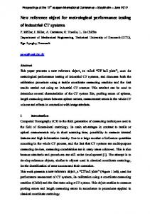
FIG. 1. The coordinate system of the modeled rectangular prism with the coordinate system defined with Origo at the center of the prism. Note that the z-direction is the “thin” direction, i.e., 2c Ⰶ 2a.
Hdem共r,T兲 =
The internal magnetic field can be written in the general form 共3兲
H = Happl + Hdem ,
where the difference between the internal and external field is the demagnetizing field Hdem. The demagnetizing field can be expressed as an integral over the interior ⍀ of the body in the following manner Hdem共r,T兲 =
1 4
冕
⍀
冕 ⬘冕 ⬘冕 a
b
dx
c
dy
−a
−b
dz⬘D共r − r⬘兲
−c
· M兵H关r⬘,T共r⬘兲兴,r⬘,T共r⬘兲其.
共5兲
Dividing the prism into nx ⫻ ny ⫻ nz rectangular cells 共following Refs. 10 and 11兲 the integral in Eq. 共5兲 may be written as a sum of integrals over each cell n
n
n
1 x y z Hdem共r,T兲 = 兺兺兺 4 i=1 j=1 k=1
dr⬘D共r − r⬘兲 · M关H共r⬘,T兲,r⬘,T兴, 共4兲
where D is a symmetric 3 ⫻ 3 tensor whose components are given in Appendix A. This expression is valid both for points r inside and outside the body. The magnetization is in general a function of both the internal field, position and temperature. The explicit position dependence is relevant when, e.g., a multimaterial prism is considered. Due to the appearance of the internal field in M, Eq. 共4兲 becomes an implicit equation for the demagnetizing field. Only when the magnetization is independent of the internal field, the equation may be evaluated explicitly. For constant magnetization this may be done either by direct integration4 or through a Fourier transform approach.6,7 At low applied fields the magnetization within a soft ferromagnetic body will form domains in order to minimize the magnetostatic energy. Upon application of a modest magnetic field the domains will be aligned bringing the ferromagnet into a single-domain, saturated state. This saturated state is always assumed in the following. To assume that the magnetization will not depend on the internal field will be a fair approximation for ferromagnetic bodies at temperatures far below the Curie temperature. However, close to the Curie temperature the magnetization has a strong field dependence. In the following, we will assume that the mean field equation of state captures the essential aspects of this dependence for the purpose of calculating the demagnetizing field. We do not expect our results to differ markedly for more realistic equations of state. For concreteness we will only consider rectangular prisms. However, the procedure below may readily be adapted to, e.g., multimaterial spheres or cylinders. Considering now a rectangular prism bounded by the inequalities −a ⱕ x ⱕ a, −b ⱕ y ⱕ b, and −c ⱕ z ⱕ c 共see Fig. 1兲 the demagnetizing field may be expressed as
1 4
冕 ⬘冕 ⬘冕 a⬘
−a⬘
dx
b⬘
−b⬘
dy
c⬘
−c⬘
dz⬘
D共r − r⬘兲 · M兵H关r⬘,T共r⬘兲兴,r⬘,T共r⬘兲其
共6兲
with a⬘ = a / nx, b⬘ = b / ny, and c⬘ = c / nz. Each cell has the same relative dimensions as the original prism. Assuming each cell to be sufficiently small to have constant magnetization, M0共r⬘i,j,k , Ti,j,k兲, Eq. 共6兲 may be approximated by nx n y
nz
Hdem共r,T兲 ⬇ − 兺 兺 兺
i=1 j=1 k=1
N共r − r⬘i,j,k兲 · M0关H共r⬘i,j,k,Ti,j,k兲,r⬘i,j,k,Ti,j,k兴, 共7兲 where N denotes the symmetric 3 ⫻ 3 demagnetization tensor field with the components given in Eqs. 共A8兲 and 共A12兲 below. The vector r⬘i,j,k denotes the center of the cell with index i , j , k. The magnetization is generally a function of both the magnitude of the internal field, H, and temperature, T. Therefore, Eq. 共3兲 has to be solved by iteration. For simplicity the magnetization is assumed to be aligned with H, i.e., there is no magnetocrystalline anisotropy.4 To obtain the magnitude of the magnetization, M, the mean field equation of state for a ferromagnet is assumed12 M共T,H兲 = NsgJBBJ共兲
共8兲
with Ns denoting the number of magnetic spins per unit mass, g the Landé factor, J the total angular momentum in units of ប, B the Bohr magneton, and the mass density. The Brillouin function, BJ, is defined as B J共 兲 =
冉
冊
冉 冊
2J + 1 1 2J + 1 1 coth − coth , 2J 2J 2J 2J
共9兲
Downloaded 24 Jun 2010 to 192.38.67.112. Redistribution subject to AIP license or copyright; see http://jap.aip.org/jap/copyright.jsp
103910-3
J. Appl. Phys. 107, 103910 共2010兲
Smith et al.
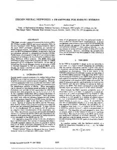
FIG. 2. The concept of grading the prism with different ferromagnets. In this case five materials are illustrated. The Curie temperatures differ from layer to layer as indicated by TC1−5.
=
3TCJ gJB0H + BJ共兲. k BT T共J + 1兲
共10兲
Here the vacuum permeability, 0, the Boltzmann constant, kB, and the Curie temperature, TC, were introduced. Equation 共10兲 is iterated to obtain a self-consistent solution. In Appendix B a numerical model solving the coupled problem in Eqs. 共3兲–共10兲 is described in detail. III. APPLICATION OF THE MODEL
Four different cases are investigated in the following. Two cases with a rectangular prism made of a single magnetic material, i.e., having one Curie temperature, and two cases with a so-called graded material, i.e., a composite material which contains regions with different Curie temperatures. In the latter case, the grading is assumed to be along the x-direction; for concreteness we consider five equal-sized regions each with its own Curie temperature 共illustrated in Fig. 2兲. This is presented in Sec. III B. Both materials configurations are considered under two different temperature situations: one with a constant temperature and one with an imposed temperature gradient. The latter case is relevant to investigate for, e.g., magnetic refrigeration, or in other cases where a thermal gradient is present in the system. In general, such a gradient may cause the prism to be in different magnetic phases at the same time. This is the typical operation mode of a magnetic material used in magnetic refrigeration, which will be roughly centered around the Curie temperature for optimal utilization of the magnetocaloric effect.13 As a magnetic material, gadolinium 共Gd兲 is used since it can be fairly well described by the mean field equation of state, Eq. 共8兲;14 additionally it acts as a de facto benchmark material in magnetic refrigeration. The Curie temperature of Gd is taken to be 293 K, and the other input parameters for the mean field equation of state are given in Table I. The dimensions of the prism are taken to be 2a = 0.02 m, 2b = 0.02 m, and 2c = 0.001 m in all cases. The coordinate system is illustrated in Fig. 1. TABLE I. Parameters for the mean field equation of state, Eq. 共8兲, for Gd. Data taken from Refs. 15 and 16.
Parameter Value
Ns 共kg−1兲
g 共⫺兲
J 共ប兲
共kg m−3兲
TC 共K兲
3.83⫻ 1024
2
7/2
7900
293
(a)
(b)
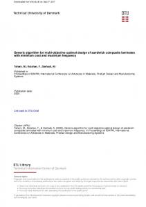
FIG. 3. The normalized mean of the magnetic field as a function of the 共spatially constant兲 temperature for four different applied fields in the case of a rectangular prism consisting of one magnetic material. 共a兲 The applied field is along the x-direction. 共b兲 The applied field is along the z-direction.
A. Single Curie-point flat prism 1. Constant temperature
We first consider the case of a single material with a constant temperature to validate our approach. This is a wellknown situation and will only briefly be discussed. In Fig. 3 the normalized mean of the magnitude of the internal field is plotted as a function of the 共spatially constant兲 prism temperature for four different applied fields. It is evident from the figure that the effect of demagnetization decreases at higher applied fields in the ferromagnetic phase. This follows directly from the fact that the magnetization is saturated in the ferromagnetic phase and thus the demagnetizing field becomes constant. However, a field of more than 5 T is needed in order for this to be the case 共this field value is material dependent, of course兲. Furthermore, when applying the field in the xy-plane of the prism, the magnetic field is reduced with a few percent whereas it is reduced with up to 70% in the case of applying the field along the z-direction. The decrease is dependent on temperature and material properties. 2. Linear temperature profile
In the following, the rectangular prism is assumed to have an imposed temperature profile ranging linearly from 280 to 300 K along the x-direction. This will make the magnetic state of the prism depend on x. This is a special case of great importance in, e.g., magnetic refrigeration where a magnetic material acts both as a regenerator material, i.e., upholding a thermal gradient, and as an active magnetic material through the magnetocaloric effect. Figure 4 shows the two cases where the applied field is along the x-direction and z-direction, 共a兲 and 共b兲, respectively. Four different fields have been applied, namely 1.0, 1.5, 2.0, and 5.0 T. The same trends as in Fig. 3 are observed. The rather large applied magnetic field of 5 T saturates the magnetization 共in the ferromagnetic phase兲 and the effect of demagnetization is thus small here. However, considering the cases of applied fields of 1.0–2.0 T a rather large gradient in the internal field is observed when the applied field is along the z-direction 关Fig. 4共b兲兴. In the case of applying the field along the x-direction 关Fig. 4共a兲兴, the internal field is generally not affected greatly by the demagnetizing field. However, on the low temperature edge, i.e., where x / a = −1, the field drops rapidly. A similar, though not as large, drop is seen on the
Downloaded 24 Jun 2010 to 192.38.67.112. Redistribution subject to AIP license or copyright; see http://jap.aip.org/jap/copyright.jsp
103910-4
J. Appl. Phys. 107, 103910 共2010兲
Smith et al.
(a) (a)
(b)
(b)
FIG. 4. The magnetic field along the line y = 0, z = 0, and −1 ⱕ x / a ⱕ 1. The prism has an imposed thermal gradient along the x-direction ranging from 280 to 300 K and consists of one magnetic material with a Curie temperature of 293 K. 共a兲 The applied field is along the x-direction. 共b兲 The applied field is along the z-direction.
high temperature edge 共at x / a = 1兲. These two drops in the internal field are due to the fact that the demagnetization tensor field is largest on the edges perpendicular to the direction of the applied field. The reason that the lower temperature edge has the somewhat greater drop in internal field is because this part of the prism is in the ferromagnetic phase and thus the magnetization is largest here and consequently the demagnetizing field is greater.
(c) FIG. 5. The magnitude of the magnetic field along the line defined as −1 ⱕ x / a ⱕ 1, y = 0, and z = 0 through the prism for five different constant temperatures. The prism is divided in five regions each being a magnetic material resembling Gd but with different Curie temperatures 共280 K, 285 K, 290 K, 295 K, and 300 K, respectively兲, as illustrated in Fig. 2. 共a兲 The applied field is along the x-direction. 共b兲 The applied field is along the y-direction. 共c兲 The applied field is along the z-direction. In all cases 0Happl = 1.0 T.
B. Flat prism with multiple Curie temperatures
In the following a rectangular prism consisting of five equally distributed magnetic materials resembling Gd but with Curie temperatures 280 K, 285 K, 290 K, 295 K, and 300 K, respectively, is considered. The grading of the prism is along the x-axis. With the temperature of the prism in the interval 280 to 300 K the individual parts of the prism will be in different magnetic phases but still in the vicinity of their respective Curie temperatures.
when the magnetic field is applied along the y-axis. Since H is virtually constant 共to within a few per mille; see Fig. 5兲, the magnetization is dominating the spatial variation in B. This is seen in the staircaselike plot on Fig. 6共b兲. At, e.g., a constant temperature of 280 K, the value of B in the part of the prism with a Curie temperature of 280 K is equal to B at a temperature of 285 K in the part of the prism with a Curie
1. Constant temperature
Considering the case with the prism having a constant temperature the magnitude of the internal field across the prism in the direction of the grading is plotted in Fig. 5 for five different constant temperatures. The applied field is in all cases equal to 1 T. The magnetic field is seen to be discontinuous in the x-direction when applying the field in this direction 关Fig. 5共a兲兴, whereas it is continuous in the x-direction when applying the field along the y-direction and z-direction 关Figs. 5共b兲 and 5共c兲兴. This is to be expected since in the former case the magnetic field lines are crossing material boundaries and the normal component of H is discontinuous. In the latter cases the field lines are perpendicular to the materials boundaries and the parallel component of H across boundaries is continuous as expected. It should be noted that the largest component of H is along the direction of the applied field. Considering the magnetic flux density, B = 0共H + M兲,
共11兲
the opposite is true, i.e., the normal component is continuous whereas the parallel component is discontinuous. This is seen in Figs. 6共a兲 and 6共c兲. Figure 6共b兲 shows a plot of the magnitude of the magnetic flux density along the x-axis
(a)
(b)
(c) FIG. 6. The magnitude of the magnetic flux density, B, along the same line as in Fig. 5, i.e., −1 ⱕ x / a ⱕ 1, y = 0, z = 0 for five different temperatures. The prism is the same as considered in Fig. 5. 共a兲 The applied field is along the x-direction. 共b兲 The applied field is along the y-direction. 共c兲 The applied field is along the z-direction. In all cases 0Happl = 1.0 T.
Downloaded 24 Jun 2010 to 192.38.67.112. Redistribution subject to AIP license or copyright; see http://jap.aip.org/jap/copyright.jsp
103910-5
J. Appl. Phys. 107, 103910 共2010兲
Smith et al.
point of 285 K, etc. The discontinuities across the internal materials boundaries are expected again due to the boundary conditions. When applying the magnetic field along the x-direction, which causes minimal demagnetization, it is observed that the variation in the temperature of the prism does not change the internal field significantly. However, when applying the field along the z-direction, Fig. 5共c兲, a significant difference is observed between the various temperature cases. The lower the temperature of the prism the more of the individual composites are in their ferromagnetic state. This produces higher magnetization values and thus also a larger demagnetizing field. For increasing Curie temperature 共along the x-axis兲 the magnetic field decreases because of the larger magnetization. It should be noted that for a constant temperature of 280 K the average internal field is about 60% of the applied field. The maximum decrease is observed to be around 80% for the cases studied here. The reason for the increase in magnetic field at either ends for all temperature cases is the relatively low demagnetization factor on the boundary. It is noted that the internal field may actually be greater than the applied field locally. This is seen in Fig. 5共a兲 and can be explained by flux shimming due to the discontinuity in the permeability on the boundary between two different magnetic materials.9 Finally, it is noted that applying the field along the y-direction 关Fig. 5共b兲兴 yields both a continuous and large internal magnetic field. The difference in this situation between the largest and smallest values of the magnitude of the internal field is only a few percent whereas in the case of applying the field along the x-direction may give a decrease in as much as 30%, though only in relatively small regions. 2. Linear temperature profile
Figure 7 shows the magnetic field in the x-direction of a prism similar to the one considered in Sec. III B 1 but with an imposed linear temperature profile ranging from 280 to 300 K. For the four different applied fields, 1, 1.5, 2.0, and 5.0 T, Figs. 7共a兲–7共c兲 show the case when magnetizing along the x-direction, y-direction, and z-direction, respectively. A magnetic field similar to that obtained in the constant temperature case, Fig. 5, is produced in this case. However, when applying the field along the x-direction the drop in magnetic field at either end is similar to the edge defined as x = −a in Fig. 5共a兲. Again, as discussed in Sec. III B 1, applying the field along the y-direction 关Fig. 7共b兲兴 yields both a smooth and large internal field. This may be explained by the simple fact that the normal component of H is continuous across materials boundaries and the demagnetization is low when the field is applied in the y-direction. Finally, when applying the field along the z-direction the internal field is more smooth than in the constant temperature case 关see Figs. 5共c兲 and 7共c兲兴. This is due to the fact that each section of the prism having a specific Curie temperature is relatively close to this temperature. Thus, the magnetization across the prism is fairly constant as opposed to the decrease with increasing x in Fig. 5共b兲. This results in a more constant demagnetizing field. It is also observed in Figs. 7共a兲–7共c兲
(a)
(b)
(c) FIG. 7. The magnitude of the internal field along the line −1 ⱕ x ⱕ 1, y = 0, and z = 0 for four different applied fields. The prism is divided into five materials each having a different Curie temperature as in Fig. 5. The prism has an imposed linear temperature profile along the x-direction ranging from 280 K to 300 K. 共a兲 The applied field is along the x-direction. 共b兲 The applied field is along the y-direction. 共c兲 The applied field is along the z-direction.
that lower applied fields induce larger variation along the x-direction, which is due to the fact that the magnetization becomes saturated above a certain field and thus the demagnetizing field becomes constant. IV. COMPARISON TO THE AVERAGE DEMAGNETIZATION FACTOR
In Ref. 3 the average demagnetization factor, N, of a prism under the assumption that the magnetization and internal field are homogeneous and constant was calculated by Aharoni. In the following a comparison between the results of the model presented here and this average value is performed. Experimentally, the applied field and the mean magnetization along the direction of the applied field may be obtained. This leads to the definition of a representative average demagnetization factor, N0,i 具Hi典 = Happl,i − N0,i具M i典
共12兲
with the subscript i denoting the component of the field. It should be noted that with this definition, N0,i, is not the average of the demagnetization tensor field given in Eqs. 共A8兲 and 共A12兲. In particular, the sum of N0,x, N0,y, and N0,z need not be unity. It should rather be interpreted as a simplification of the model results in terms of a single number, which is useful when analyzing experimental data. Figure 8共a兲 shows N0,x for the case of a constant temperature, single material rectangular prism with an applied field of 1 T along the x-direction. The prism has a symmetric yz-cross section and the length is varied in the x-direction giving rise to a variation in the aspect ratio. The average demagnetization factor is seen to coincide with the Aharoni
Downloaded 24 Jun 2010 to 192.38.67.112. Redistribution subject to AIP license or copyright; see http://jap.aip.org/jap/copyright.jsp
103910-6
(a)
J. Appl. Phys. 107, 103910 共2010兲
Smith et al.
(b)
FIG. 8. The representative average demagnetization factor as defined in Eq. 共12兲. 共a兲 Shows this factor as a function of aspect ratio for a rectangular prism with quadratic cross section 共in the yz-plane兲 and varying length 共along the x-direction兲. The applied field is along the x-direction and has a magnitude of 1 T. The temperature is fixed at 293 K, i.e., the Curie temperature. 共b兲 Three specific cases where the temperature and composition of the magnetic material are varied. Case 1 is for a constant temperature of 293 K with five materials, with Curie temperatures 280 K, 285 K, 290 K, 295 K, and 300 K, respectively, spaced evenly along the x-direction. Case 2 is for the same composition as in Case 1 but with a linear temperature profile ranging from 280–300 K. Case 3 is for a single material prism with an imposed linear temperature profile also from 280–300 K. In all cases the graphs show the ratio between the respective average demagnetization factor and the single material, constant temperature average demagnetization factor.
expression almost completely. In the limits where the aspect ratio goes to zero and infinity, respectively, the demagnetization factors are equal. However, for aspect ratios from one to five the Aharoni demagnetization factor is a few percent larger than the representative average defined in Eq. 共12兲. This may be explained from the fact that the corners of the prism have a relative large impact on the demagnetization factor in these cases, i.e., the magnetization and thus internal field deviate mostly from being parallel to the applied field for this range of aspect ratios. Since the Aharoni expression assumes the magnetization to be completely parallel to the applied field, a discrepancy is to be expected. Figure 8共b兲 shows the average demagnetization factor for the constant temperature and single material case compared to the three cases: 共1兲 a rectangular prism graded with five materials as discussed in Sec. III B 1, 共2兲 same as in 共1兲 but with an imposed linear temperature profile, i.e., as discussed in Sec. III B 2, and finally 共3兲 a single material prism with an imposed linear temperature profile as discussed in Sec. III A 2. It is clearly evident from the figure that the representative average demagnetization factor is not purely geometric. In the cases investigated here the effect of grading the material or imposing a linear temperature profile is of the order of 1% only. This should be taken as a consequence of the selected cases rather than as a general rule. Indeed, Ref. 8 found their effective demagnetization factor to vary with as much as 10%–20% due to nongeometric factors. V. CONCLUSIONS AND DISCUSSION
A numerical solution to the fully coupled problem of solving for the internal magnetic field in a three-dimensional rectangular prism with spatially varying temperature, applied magnetic field and magnetization has been derived and implemented. The model was applied to several relevant cases where the orientation of a magnetic material and an applied magnetic field is crucial combined with imposed
temperature gradients. The magnetic material was assumed to be either homogeneous or a multilayered composite. From the results presented in this paper it can be concluded that detailed knowledge of the demagnetizing field throughout the sample is important in many cases. This includes the situations when the temperature is not spatially constant or the sample is a composite material consisting of several materials each having a distinct Curie temperature. Imposing a temperature gradient across the sample makes the internal magnetic field become spacially asymmetric and especially when the demagnetization tensor field is rather large the internal field may be approximately linear as shown in Fig. 4共b兲. In this case the largest value of the internal field in the sample may be 50% greater than the smallest, which certainly invalidates any assumption of constant magnetization throughout the sample. When applying a magnetic field along the direction of the grading of the material 共in this case the x-direction兲 discontinuities on each internal boundary are observed. This is a direct consequence of the boundary conditions that apply generally for H and B. This leaves two preferred directions to apply the magnetic field in 共the x-direction and y-direction, respectively兲, in order to minimize the demagnetizing field. However, a large difference is observed in the behavior of the internal magnetic field between these two cases. When the external magnetic field is applied along the x-direction, discontinuities exist at every internal material boundary due to the boundary conditions for H. In the other case, when the applied magnetic field is along the y-direction, no discontinuities are present. Furthermore, the magnitude of the internal magnetic field is generally seen to be larger in this case. It may therefore be concluded that great care should be taken when deciding along which direction the magnetic field should be applied with respect to both the demagnetizing field and a possible grading of the magnetic material. In the case of applying the magnetic field in the z-direction to a constant temperature sample a difference between single and multiple material prisms is observed. In the former case the internal field is fairly constant. In the latter case the internal field becomes almost linear in the x-direction for a range of temperatures 关see Fig. 5共c兲兴. However, when imposing a temperature gradient in the x-direction the virtually opposite is the case 关compare Figs. 4共b兲 and 7共c兲兴. An average demagnetization factor was introduced and compared to the analytical expression calculated in Ref. 3 which is based on the assumptions that the magnetization is constant and completely aligned with the applied field. However, when the prism does not have a constant temperature or is made of a composite of different magnetocaloric materials, the demagnetization factor of Eq. 共12兲 changes slightly. Finally, it is concluded that the internal magnetic field is far from being constant under realistic circumstances and that it may be a poor approximation to assume so. As expected, when imposing a temperature gradient across the rectangular prism and assuming a composite material the internal field can become highly inhomogeneous, depending on the orientation of the applied field. Such inhomogeneities
Downloaded 24 Jun 2010 to 192.38.67.112. Redistribution subject to AIP license or copyright; see http://jap.aip.org/jap/copyright.jsp
103910-7
J. Appl. Phys. 107, 103910 共2010兲
Smith et al.
are important in any case where a good representation of the internal field is sought. It is noted that the results of this paper are valid for single prisms only. In many situations stacks or arrays of prisms will be relevant. A future paper on this using the model presented here is in preparation. ACKNOWLEDGMENTS
The authors thank the support of the Programme Commission on Energy and Environment 共EnMi兲 共Contract No. 2104-06-0032兲 which is part of the Danish Council for Strategic Research.
Dii共r兲 = −
Dij共r兲 =
Ai共r兲 =
0 mi ⫻ 共r − r⬘兲 . 4 兩r − r⬘兩3
Hdem共r兲 =
0 4
冕
⍀
dr⬘
Nii共r兲 =
H共r兲 =
1 1 B共r兲 − M共r兲 = ⵜ ⫻ A − M共r兲 0 0
=−
1 4
冕
⍀
dr⬘共M共r⬘兲 · ⵜ兲
r − r⬘ , 兩r − r⬘兩3
共A3兲
which is the required demagnetizing field, Hdem. The differentiations can be performed straightforwardly, giving rise to the following equation Hdem共r兲 =
1 4
冕
⍀
dr⬘D共r − r⬘兲 · M共r⬘兲,
共A4兲
with D being a symmetrical 3 ⫻ 3 tensor with elements
Nij共r兲 = −
冋
1 4
冕 冕 冕 a
b
dx⬘
−a
c
dy ⬘
−b
dz⬘D共r − r⬘兲 · M0
−c
共A7兲
1 关arctan f i共x,y,z兲 + arctan f i共− x,y,z兲 4 + arctan f i共x,− y,z兲 + arctan f i共x,y,− z兲 + arctan f i共− x,− y,z兲 + arctan f i共x,− y,− z兲
共A2兲
Note that this gives the vector potential both inside and outside of the prism. The resulting H-field is
共A6兲
where the symmetric 3 ⫻ 3 demagnetization tensor N共r兲 has the components
共A1兲
M共r⬘兲 ⫻ 共r − r⬘兲 . 兩r − r⬘兩3
i⫽j
= − N共r兲 · M0 ,
The total vector potential of a magnetic body is obtained by integrating over the interior of the body 共with mi = MdV兲: A共r兲 =
3xix j , 兩r兩5
共A5兲
Considering a rectangular prism with constant magnetization, M共r兲 = M0,4 the demagnetizing field becomes
APPENDIX A: CALCULATING THE D TENSOR FIELD
The vector potential of a single magnetic dipole at r⬘ is
3x2i 1 + 兩r兩3 兩r兩5
+ arctan f i共− x,y,− z兲 + arctan f i共− x,− y,− z兲兴 共A8兲 where f x共x,y,z兲 =
共b − y兲共c − z兲 共a − x兲关共a − x兲2 + 共b − y兲2 + 共c − z兲2兴1/2
f y共x,y,z兲 =
共a − x兲共c − z兲 共b − y兲关共a − x兲2 + 共b − y兲2 + 共c − z兲2兴1/2
共A9兲
共A10兲 f z共x,y,z兲 =
共b − y兲共a − x兲 . 共c − z兲关共a − x兲2 + 共b − y兲2 + 共c − z兲2兴1/2 共A11兲
The off-diagonal elements are
册
1 Fij共r,a,b,c兲Fij共r,− a,− b,c兲Fij共r,a,− b,− c兲Fij共r,− a,b,− c兲 ln , 4 Fij共r,a,− b,c兲Fij共r,− a,b,c兲Fij共r,a,b,− c兲Fij共r,− a,− b,− c兲
i⫽j
共A12兲
Fxz共r,a,b,c兲 = 共b − y兲 + 关共a − x兲2 + 共b − y兲2 + 共c − z兲2兴1/2 .
where
共A15兲 Fxy共r,a,b,c兲 = 共c − z兲 + 关共a − x兲 + 共b − y兲 + 共c − z兲 兴 2
2
2 1/2
共A13兲
Fyz共r,a,b,c兲 = 共a − x兲 + 关共a − x兲2 + 共b − y兲2 + 共c − z兲2兴1/2 共A14兲
APPENDIX B: NUMERICAL IMPLEMENTATION OF THE MODEL
This appendix describes the implementation of a numerical model for solving the demagnetization problem as stated in Eqs. 共3兲 and 共7兲. First a simple scheme for optimized
Downloaded 24 Jun 2010 to 192.38.67.112. Redistribution subject to AIP license or copyright; see http://jap.aip.org/jap/copyright.jsp
103910-8
J. Appl. Phys. 107, 103910 共2010兲
Smith et al.
(a)
(b)
FIG. 10. The mean of the internal magnetic field as a function of the number of grid points for three different constant temperatures and an applied field of 1.0 T applied along the x-direction 共a兲 and an applied field of 0.5 T applied along the z-direction 共b兲. FIG. 9. The mean of the internal magnetic field as a function of number of iterations for the case when applying the magnetic field in the z-direction, setting the temperature to be constant at 285 K 共below the Curie temperature兲 and 0Happl = 0.5 T.
convergence conditions is presented. Second, the resolution of the model is discussed. Finally, symmetry conditions and parallelization are considered since the problem is of order n2 with n = nx ⫻ ny ⫻ nz. 1. Convergence
The criterium for convergence is defined as the maximum difference between the internal magnetic fields in two following iterations should be less than 10−8 T. This is a criterium that is very similar to that of Ref. 8. An underrelaxation technique on the magnetization for obtaining convergence in situations with small applied fields and/or temperatures below the Curie temperature was applied in Ref. 8. By thorough testing, we found that under-relaxing on the internal field was better for convergence. This may be expressed as Hn+1 = Hn + n关H共M n兲 − Hn兴,
共B1兲
where n denotes the iteration step, H0 = Happl, M n = M共Hn兲 using Eq. 共8兲 and assuming M to be parallel to H in the previous step and H共M n兲 is obtained through Eqs. 共3兲 and 共7兲. The under-relaxation parameter for the nth iteration is denoted n, which attains a value in the interval 0 ⬍ n ⱕ 1. Finally, it is noted that Eq. 共B1兲 is used on every mesh point and the convergence is determined from the mesh point where two consecutive iterations yield max关abs共Hn − Hn+1兲兴 ensuring the slowest but most precise convergence. Figure 9 shows an example of the under-relaxation technique. 2. Resolution
A variation in resolution is shown in Fig. 10. The resolution of the prism is in all cases, except when comparing to the average demagnetization factor, 共nx , ny , nz兲 = k共2a , 2b , 10 ⫻ 2c兲 with k being an arbitrary scaling constant. As can be seen from the figure a fairly low resolution is sufficient. This corresponds to 共nx , ny , nz兲 = 共20, 20, 10兲 for the case discussed in this work.
3. Symmetry and optimization
The solution to the problem stated in Eqs. 共3兲 and 共7兲 both involves iteration of Eq. 共3兲 and an n2 problem from Eq. 共7兲. Optimization in the form of exploitation of symmetry should be employed. The rectangular prism is symmetric around all three axes meaning that only one octant needs be considered when calculating the demagnetization tensor field, N. Obviously, the applied field, temperature and magnetization cannot a priori be assumed to be symmetric since realistic scenarios include both temporally and spatially varying magnetic fields and temperatures. However, the nature of N is purely geometric and is thus only a function of r − r⬘i,j,k, a⬘, b⬘, and c⬘. Since the grid is defined to be homogeneous, the calculation of N only has to be performed once 共at the beginning of the iteration process兲. Furthermore, N needs only to be evaluated in one octant and from this result can be mirrored to the remaining part of the coordinate system. Finally, during the calculations needed for one iteration, the value of M is obtained from the previous iteration 共or, in the case of the first iteration, from the initial guess兲, which means that the evaluations of the dot products between N and M needed in Eq. 共7兲 are completely decoupled, which results in the possibility of maximized parallelization. P. M. Levy and D. P. Landau, J. Appl. Phys. 39, 1128 共1968兲. J. A. Osborn, Phys. Rev. 67, 351 共1945兲. A. Aharoni, J. Appl. Phys. 83, 3432 共1998兲. 4 R. I. Joseph and E. Schloemann, J. Appl. Phys. 36, 1579 共1965兲. 5 M. Beleggia and M. De Graef, J. Magn. Magn. Mater. 263, L1 共2003兲. 6 S. Tandon, M. Beleggia, Y. Zhu, and M. De Graef, J. Magn. Magn. Mater. 271, 9 共2004兲. 7 S. Tandon, M. Beleggia, Y. Zhu, and M. De Graef, J. Magn. Magn. Mater. 271, 27 共2004兲. 8 J. A. Brug and W. P. Wolf, J. Appl. Phys. 57, 4685 共1985兲. 9 O. Peksoy and A. Rowe, J. Magn. Magn. Mater. 288, 424 共2005兲. 10 M. Lu, Z. Yang, and F.-L. Wei, Int. J. Infrared Millim. Waves 19, 1027 共1998兲. 11 M. Schabes and A. Aharoni, IEEE Trans. Magn. 23, 3882 共1987兲. 12 A. H. Morrish, The Physical Priciples of Magnetism 共Wiley, New York, 1965兲. 13 A. Rowe and A. Tura, Int. J. Refrig. 29, 1286 共2006兲. 14 G. J. Liu, J. R. Sun, J. Z. Wang, T. Y. Zhao, and B. G. Shen, J. Phys.: Condens. Matter 19, 466215 共2007兲. 15 D. R. Lide, CRC Handbook of Chemistry and Physics 共CRC, Boca Raton, FL, 2004兲. 16 A. M. Tishin and Y. I. Spichkin, The Magnetocaloric Effect and its Applications 共Institute of Physics, London, 2003兲. 1 2 3
Downloaded 24 Jun 2010 to 192.38.67.112. Redistribution subject to AIP license or copyright; see http://jap.aip.org/jap/copyright.jsp