The design and implementation of a quality-based handover trigger
Recommend Documents
failure probability and probability of false handover initiation may be reduced in WiMAX networks. Keywords-- WiMAX; MIH; 802.21; Link Going Down. Trigger ...
Jan 15, 2018 - In order to resolve this issue, while limiting ping-pong (PP) ... (1) Frequent handover, which generates frequent cell re-selection, communication ...
RAM of 512MB and 1.5GHz processor speed for any user to have access to the LMS. Also, it will .... Language), PHP (Hypertext Preprocessor) and JavaScript.
Abstract: Information quality assessment of technical documentation is an ... information analysis as well as software and information quality management ...... Juran, J. (1998) Juran's Quality Control Handbook, 5th ed., McGraw-Hill, New York, ...
Sep 30, 2007 - safety and to make the journey enjoyable. This is ... A robust algorithm should ensure good quality of service (QoS) ...... margin of each network.
tion of new track and trigger (T&T) scoring and response .... trigger' model, nursing staff showed ... Receive free email alerts when new articles cite this article.
Neighbor BSs, it sends results to the BS. There exist two types of results reporting. In the first,. âEvent trigger reportâ, MS sends reports based on a defined.
Trigger implementation in the KLOE experiment. V. Bocci. 2,(*). , P. Branchini. 4. , F. Bossi. 5 .... a series of monitor registers to control dead time, arrival timing of ...
In this paper, we argue for a novel mobility trigger management framework that can handle a much larger set of notifications related to events originating not only.
pipelined architecture for the trigger electronics which departs significantly from ... the detector in real time, and process and transport it in parallel. The data are ...
International Journal of Applied Engineering Research ISSN 0973-4562 Volume 12, ... Faculty of Engineering Technology, Al-Balqa' Applied University, Jordan.
ubiquitous wireless network environment. ... or vertical handovers happen across different network .... analytics applications in science, technical and business.
Lack of strong pipeline in leadership succession ... •Technical skills ..... Group;
Dave Ulrich, University of Michigan; Norm Smallwood, Results-Based
Leadership.
TeleAdvisor is a versatile projection-based augmented reality system designed ... a production line, a help desk operator remotely guiding thefixing of a printer, or a junior ... portable, hands-free projected AR solution for remote collaboration, ..
University of Washington and Utah State University. ..... has been adapted from Bar-Itzhack and Oshman.7 The estimated accuracy is 1-10⦠absolute angle error ...
Software Research and Development Center ..... Abort-on-Commit Dependency(tj ACD ti): if transaction ti com- ..... call of restart() method of guard handler.
IA32) or class or method test (default on PPC). It uses the same size heuris ...... We use the tc tool from the IPROUTE2 utility suite [Kuznetsov 1998] to manipulate.
Feb 22, 2018 - iMessage capable device. Keywords: wearable fall detector; Bluetooth low energy; accelerometer; fall detection algorithm. 1. Introduction.
A flash and flash media server are used to turn on a web camera connected .... Many descriptions have been used during the years, to define what NC is.
Nov 28, 2011 - Figure 1. (a) Oval path followed by the legs of a freshwater turtle. ... develop a turtle-like AUV using hydrofoil propulsion. To this end, this work ...
Level Controller using Fuzzy Logic. Namrata Dey#1, Ria Mandal#2, M Monica Subashini#3. # School of Electrical Engineering, VIT University. Vellore â 632014 ...
+966538581611; email: [email protected], [email protected]. Manuscript ..... Moreover, Web portal creation can be developed in this system in order ...
The design and implementation of a quality-based handover trigger
it consists of a mobile terminal, a server we call a PBX, and load generating nodes .... Losses recorded at a stationary terminal (left) and a stationary PBX (center).
The design and implementation of a quality-based handover trigger Ian Marsh1 , Bj¨orn Gr¨onvall1 , and Florian Hammer2 1
2
SICS, Kista, Sweden {ianm,bg}@sics.se Telecommunications Research Center (ftw.) Vienna, Austria [email protected]
Abstract. Wireless connectivity is needed to bring IP-based telephony into serious competition with the existing cellular infrastructure. However it is well known that voice quality problems can occur when used with unlicensed spectrum technologies such as the popular IEEE 802.11 standards. The cellular infrastructure could provide alternative network access should users roam out of 802.11 coverage or if heavy traffic loads are encountered in the 802.11 cell. Therefore, our goal is to design a handover mechanism to switch ongoing calls to the cellular network when the 802.11 network cannot sustain call quality. We have investigated load and coverage scenarios and designed, implemented and evaluated the performance of an 802.11 quality-based trigger for the handover of voice calls to the cellular network. We show that our predictive solution addresses the coverage problem and evaluate it within a real setting.
Handsets that are equipped with multiple standard radios will become commonplace. PDAs with 2G cellular radios and IEEE 802.11 chipsets are already on the market, and dual-radio mobile phones are also beginning to appear. The primary motivations for a voice handover system are monetary. By connecting to 802.11 access points when available, it should be possible to avoid cellular tariffs. However when users leave the 802.11 area they may want to continue their voice calls. Therefore a handover mechanism for voice users is desirable. Excess traffic within the 802.11 cell is also a reason to handover a call to the cellular system. The basic problem is when to perform, or even schedule, a handover from one system to the other. The cellular infrastructure provides network support for its clients, and performs the handover on their behalf. The clients report periodically their reception status enabling the infrastructure to make an informed decision. In an 802.11 system this functionality is not available, therefore it becomes the task of the handset to determine when best to handover a session. Prediction is the key issue as a voice call setup takes approximately five
seconds to the fixed or cellular network. This is an average value we measured by ringing several times to the fixed PSTN and GSM mobile networks. During the change of networks, ideally no quality differences should be audible making the handover as transparent as possible. On the other hand, the system should not handover voice calls to the cellular system due to small audio glitches that many mobile users have become accustomed to, worse still switch back or forth between network types. Manual switching should always be an option, if users want to use the cellular network. However, in this work we assume that users normally want to use the 802.11 networks for voice communication when available. Therefore the contribution of this work is an automatic handover solution for real-time voice sessions on 802.11 networks to the cellular infrastructure.
2
Assessing the influence of packet loss using PESQ
Packet loss is critical when determining voice quality. Bursty losses are well known to be commonplace in wireless communication, and 802.11 networks are no exception. Therefore the goal of this first evaluation is to ascertain how many packets can be lost in a burst without significant reductions in the perceptual quality. We do not consider delay or jitter, as they are not part of PESQ quality estimation. Since tests that involve people are timely and expensive to conduct, the recent trend has been towards using computers for evaluating speech quality.
Reference Signal
Network
Preprocesing
Psychoacoustic Modeling
Degraded Signal
Preprocesing
Quality Estimation Algorithm
Psychoacoustic Modeling
Mean Opinion Score (MOS)
Fig. 1. The PESQ processing structure.
PESQ MOS 4.5 4 3.5 3 2.5 2 1
Linguistic equivalent Excellent Good Good/Fair Fair Fair/Poor Poor Bad
Quality degradation None Moderate Severe
Fig. 2. A quality degradation scale.
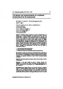
Figure 1 shows the functional units of PESQ, the ITU-T standard we derive our loss tolerances from [7]. A reference speech signal is transmitted through a network that results in a quality degradation corresponding to the path conditions and coding scheme. PESQ analyzes both the reference and degraded signal and calculates their representation in the perceptual domain based on a psychoacoustic model of the human auditory system. The disturbance between the original and the degraded speech signal is calculated by the quality estimation algorithm and a corresponding subjective Mean Opinion Score (MOS) is derived. The evaluation of speech quality using PESQ is performed off-line due to its computational complexity. For example a 400 packet sequence with ten
PESQ MOS Score
losses requires approximately two seconds of processing time for simple G.711 coded speech. G.711 yields the maximum PESQ score (4.5) in the absence of loss, however it is particularly sensitive to packet loss even with concealment. Therefore we consider the number of lost packets using G.711 as the worst case, other coding schemes would yield better quality during packets loss. It is the format used in our fully integrated solution, and thus allows us to directly set the loss thresholds in the handover trigger function without any transformation. The handover design is described within section 4. Figure 2 shows the PESQ MOS scale as defined by the ITU and their English linguistic equivalents. We have added an extra column, quality degradation, to indicate the quality reductions we have looked at as part of this work. The degradation of a MOS point is referred to as ”moderate” and for two points as ”severe”. We degrade the complete ITU-standardized eight second speech sample with between 1 to 50 continuous loss bursts. For each loss burst, we record the MOS score, and then shift it through the eight second sample until it has been completely assessed for loss sensitivity. The technique and its effectiveness is fully described in [2]. Since the results are highly influenced by the performance of the packet loss concealment (PLC) algorithms, we conducted the tests with and without PLC. The loss concealment algorithm used was the one standardized by the ITU for G.711 called G.711i [6].
4.5 4 3.5 3 1 loss 5 losses
2.5 0
100
200
300
400
Quality Language reduction Gender English French Japanese Male 3/7 9/12 4/8 Moderate Female 4/7 4/8 3/8 Male 30/31 43/45 45/46 Severe Female 31/32 46/48 45/48
Loss position in an 8 second sample
Fig. 3. Singular & quintuple loss scores for a female English speech sample.
Fig. 4. Packet loss lengths for 1 & 2 MOS reductions. The first value of the X/Y pair is without using PLC, the second is with PLC.
Examples of a single and quintuple consecutive loss lengths with loss concealment are shown in Figure 3. The samples are from an American English female, the spoken text reads “She broke her new shoelace that day, the coffee stand is too high for the couch” and lasts for seven seconds. Observe that the concealment works well for one lost packet, however five consecutive losses are more difficult to conceal, resulting in a lower PESQ score. Also note the silence period between samples 225 and 300 corresponding to the pause between the two phrases. The results for three different languages are given in Figure 4. The 90% percentile was taken for the MOS scores. As one can see the maximum number of consecutive packets one should allow in a burst without PLC is three
for a moderate drop in quality for an English speaker. However in reality loss concealment is employed, in our full working system too, so we take seven as the threshold. English is the most sensitive amongst these three particular samples.
3
Emulating a mobile system
We move onto understanding the effect of other parameters on the design of a handover trigger by creating an experimental testbed. Our experiments have three major goals, first to gauge the impact of distance on wireless VoIP communication, second to understand the dynamics of voice streams mixed with TCP downstream traffic, and third how to measure and combine the available metrics suitable for implementing a handover trigger. Figure 5 shows the setup, it consists of a mobile terminal, a server we call a PBX, and load generating nodes. The PBX connects VoIP calls to the Public Switched Telephone Network (PSTN) and has the capability to handover calls to the cellular network when requested. The PBX and load generator are on a 100 Mbits/sec Ethernet, the mobile node and the sink are on the 802.11b network. TCP load generator (downstream traffic)
Fig. 5. The experimental testbed setup used in emulating a system capable of handover.
Fig. 6. The office layout used for our quality tests with “walk” marked.
The target network is expected to be used for voice applications, but also for traditional TCP-based applications such as email and web surfing. Therefore, we have developed a TCP load generator which attempts to create flows targeting a specified rate when network resources permit. For our stated goal of the design of a quality-based handover trigger, we will now explain three separate experiments: Fading signal experiment: In this setup the mobile terminal moves past an access point and out of its coverage area. This is shown in Figure 6 as the arrowed line. The mobile terminal was carried along a corridor at walking speed and away from the access point. The left and center plots within Figure 7 show how voice packets arrive late or are lost due to environmental variations. From the figure we can see that during normal interference conditions there is little packet loss.
10
20
30
Time (seconds)
40
50
40 35 30 25 20 15 10 5 0
Signal/noise at mobile 60
Loss
S/N Smoothed
50 S/N (dB)
Loss
0
Consecutive losses at PBX Delta sequence number
Delta sequence number
Consecutive losses at mobile 40 35 30 25 20 15 10 5 0
40 30 20 10 0
0
10
20
30
Time (seconds)
40
50
0
10
20
30
40
50
Time (seconds)
Fig. 7. Consecutive losses observed by the moving terminal (left) and the PBX (center) and signal strength as reported by the terminal (right).
As the signal deteriorates however, losses become much more frequent and the length of the loss bursts increase. One interesting observation is that packet losses occur much earlier at the mobile than at the PBX, see the left and center plots. We assume this is due to the more sensitive antenna at the access point, a more sensitive antenna is probably better suited to receiving weak signals. Packet losses are first experienced at the mobile, but in the target system it is the PBX that will perform the handover. This is because the functionality to handle both PSTN and IP calls is within the PBX. Therefore the PBX needs to be continuously monitoring the signal and network conditions at the mobile. This information can be sent either by piggybacking data onto the voice packets, or by sending RTCP-like designated packets at fixed time intervals. From a system point design perspective, it is critical that the PBX knows the state of the mobile by receiving packets or indeed not, from it. The right plot of Figure 8 depicts how the mobile varies the transmission rate over time. During good signal conditions the mobile always uses the maximum transmission rate. During reasonable conditions the mobile varies the rate as it discovers link layer retransmissions become necessary [8, 9]. During poor conditions it constantly transmits at 1 Mbit/s. Notice that 1 Mbit/s is a critical point, as at this point it could lose connectivity altogether. Thus, when transmitting at 1 Mbit/s, a handover to the cellular network should be considered imminently, however it is not necessarily true that operating at 1 Mbit/s implies poor quality. Observe that a handover to the cellular network should ideally have completed at t = 36, which would have meant scheduling the handover approximately at t = 31 (the left plot of Figure 8), otherwise, poor quality could be experienced before the cellular call is in progress. Loaded network: In this experiment we study the effects of a network operating close, but below, its full capacity. The synthetic load is limited to a target rate by our load generator. Due to the TCP behavior, the network will be overloaded for short periods of time. The synthetic load is directed towards (into) the 802.11 network in order to simulate web browsing or an email download. In this experiment we monitor an ongoing call and after ten seconds add synthetic load so that the network is operating at almost its full capacity. After a further
One-way delay at mobile
One-way delay at PBX 100
80 60 40 20 0
Transmission rate at mobile
Delay Smoothed
80
Rate (Mbit/s)
Delay Smoothed
Delay (ms)
Delay (ms)
100
60 40 20 0
0
10
20
30
40
50
0
Time (seconds)
10
20
30
40
14 12 10 8 6 4 2 0
50
Rate Smoothed
0
10
Time (seconds)
20
30
40
50
Time (seconds)
Fig. 8. Delays at the moving terminal (left) and the PBX (center) and changing transmission rates recorded at the terminal (right).
Time (seconds)
Consecutive losses at PBX 20 Loss 18 16 14 12 10 8 6 4 2 0 0 5 10 15 20 25 30 35 Time (seconds)
Signal/noise at mobile
S/N (dB)
Consecutive losses at mobile 20 18 Loss 16 14 12 10 8 6 4 2 0 0 5 10 15 20 25 30 35
Delta sequence number
Delta sequence number
ten seconds stop the synthetic load. In the left plot of Figure 9, we observe how the mobile at time t = 10 experiences a contiguous sequence of 13 packets that are delayed for more than 20ms and are effectively lost. This is because we used a constant size jitter buffer of 20ms in both the terminal and PBX.
60 50 40 30 20 10 0
S/N Smoothed 0
5
10 15 20 25 30 35 Time (seconds)
Fig. 9. Losses recorded at a stationary terminal (left) and a stationary PBX (center) shown with signal strengths (right) on a loaded network.
At the same time, we can see in the left graph of Figure 10 how the delay increases for each packet on its way from the PBX to the mobile, a queue is building up in the access point. The web servers are sending more packets into the 802.11 network than it can handle, and it takes time before TCP reacts and consequently backs off. During this time a queue builds up as packets arrive on the fixed network and they must be enqueued before gaining access to the congested 802.11 network. Since voice packets are delayed behind the TCP packets, they will eventually arrive late at the mobile. From the center graph of Figure 10, we can see how the delay from the mobile terminal towards the PBX increases when the network is loaded. The increase in delay is a result of the 802.11 contention, however in this case there is no extra queuing in the access point as the 100 Mbits/sec Ethernet is much faster than the 11 Mbits/sec 802.11b network. The asymmetry in the network speeds is clearly evident in these two cases. To
One way delay at mobile
One way delay at PBX
30 20 10
TX Rate at mobile
50
0
Delay 40 Smoothed 30 20 10
Rate (Mbit/s)
Delay 40 Smoothed
Delay (ms)
Delay (ms)
50
0 0
5
10 15 20 25 30 35
0
Time (seconds)
5
14 12 10 8 6 4 2 0
10 15 20 25 30 35
Rate Smoothed 0
5
Time (seconds)
10 15 20 25 30 35 Time (seconds)
Fig. 10. Delays recorded at a terminal (left) and a stationary PBX (center) shown with transmission rates (right) on a loaded network.
Time (seconds)
Consecutive losses at PBX 20 Loss 18 16 14 12 10 8 6 4 2 0 0 5 10 15 20 25 30 35 Time (seconds)
Signal/noise at mobile
S/N (dB)
Consecutive losses at mobile 20 18 Loss 16 14 12 10 8 6 4 2 0 0 5 10 15 20 25 30 35
Delta sequence number
Delta sequence number
conclude, we observe that loss events in either direction are rare, even in a loaded network. For these loss events, the burst-loss length is typically one, and these can be dealt with using standard loss concealment methods such as G.711i. Overloaded network: In a continuation of the previous experiment, but with a synthetic load driving the network to its maximum operating capacity, we will see the difference of the increased traffic load. In these experiments, we observe serious loss problems from the PBX to the mobile, but not in the reverse direction, i.e. from the mobile to the PBX. This is to be expected, as we are again observing a queue building up in the access points as TCP packets arrive. It is trivial for the mobile to detect this and promptly inform the PBX since the traffic from the terminal to the access point is still unhindered. The problem arises with the speed this can occur. The network load can increase from unloaded to full capacity in a fraction of a second, however as we know it takes several seconds to establish a call through the PSTN. A better solution than triggering a handover in this case, is to give the voice traffic higher priority e.g. by marking the speech packets as having priority as proposed by the IETF Differentiated Services framework. The access point must also be capable of detecting these and scheduling the appropriate priorities.
70 60 50 40 30 20 10 0
S/N Smoothed 0
5
10 15 20 25 30 35 Time (seconds)
Fig. 11. Losses recorded at a terminal (left) and a stationary PBX (center) and signal strength as reported by the terminal (right) on a overloaded network.
40 30 20 10 0
One way delay at PBX 50 Delay (ms)
Delay (ms)
Delay Smoothed
Delay Smoothed
40 30 20 10
TX Rate at mobile Rate (Mbit/s)
One way delay at mobile 50
0 0
5
10 15 20 25 30 35 Time (seconds)
0
5
10 15 20 25 30 35 Time (seconds)
14 12 10 8 6 4 2 0
Rate Smoothed 0
5
10 15 20 25 30 35 Time (seconds)
Fig. 12. Delays recorded at a terminal (left) and a stationary PBX (center) shown with transmission rates (right) on a overloaded network.
4
Handover design and implementation
We now consider our real system with voice-enabled PDA’s using commercial software, firmware and hardware solutions. When using real systems, the availability, reliability and resolution of network and link layer metrics are not the same on all systems. Therefore we chose not rely on one or two metrics rather to use a linear combination of those available for our trigger mechanism. Ideally we would like to use as many as possible and reliable, but certain hardware and software limitations prohibit this. The single value to make the handover decision we refer to as the handover score. The usable metrics we call the handover contributors and rationalize their inclusion in the following paragraphs. Report intervals: We have stated it is important to inform the PBX of current quality conditions at the terminal. Loss and jitter metrics are sent every 0.5 sec from the mobile terminal to the PBX. Link layer metrics are read at intervals of 0.125 sec, four times the frequency of the VoIP metrics. Since the link layer situation ultimately reflects in the quality seen at the application layer, we deemed it necessary to use higher resolution at this layer. The link layer metrics are averaged and sent with the network parameters in RTCP-like reports. The timings are a tradeoff between the measurement resolution and CPU load on a PDA. Signal strength: As we have seen the signal to noise ratio is a good indicator of potential problems. Therefore given a dependable reading, we only need to record its value and scale it to our handover score. Unfortunately the signal strength reading from the PDAs tends to bottom out long before we loose connectivity, and consequently only makes a small contribution to the handover score, which is a limitation of the terminals we used. Loss: We have seen from our off-line PESQ experiments that eight losses are sufficient to reduce the quality from “excellent” to “good/fair”. A 20ms packeti-
sation represents 50 packets per second, therefore a loss of eight packets corresponds to a loss percentage of 16% percent. In each second there are two reports (0.5 sec per report), therefore a loss of 8% should be taken into account. Jitter: We have seen increasing jitter was the best indicator we had of poor upcoming quality. In an open system it is easy to calculate the mean and variance of the VoIP stream by observing packet interarrival times. However, in our full system jitter estimates are returned from a commercial VoIP encoding and playout system called the GIPS Engine3 . We were uncertain about the exact units returned, but found from experimentation that, values between 0-68 signified good conditions, whilst those between 69-80 were interpreted as neutral, 81-93 as bad and over 94 as poor. To find these values we loaded the network as described in the emulated cases, and observed the values reported. RTCP losses: It is important that the PBX has information about the state of the mobile terminal, as if the PBX is not receiving reports then the mobile is probably having reception problems and as we have seen, more likely worse than those seen at the PBX. Therefore sending regular reports from the mobile terminal to the PBX probes the 802.11 quality, and reports indicate potential problems. We chose three or more consecutive losses as sufficiently significant to reduce the score. Handover score weighting: Since we have chosen to use a linear combination of the metrics, it is simple a matter of combining the metrics into a single score value. Handover score = Signal + Loss + Jitter + Report losses Handover score values: For convenience our implementation uses a handover score that varies between -100 and 100. A large positive value indicates good quality. The user enters a threshold value and a handover will occur when the score falls below this level. By increasing the threshold, average quality will improve but at greater expense since the system will hand over the call to the GSM system earlier. Conversely by decreasing the threshold, GSM expenses will be reduced but the periods of degraded audio quality will be longer. It was necessary to smooth these scores in some cases by considering two intervals, however we attribute this to using some combinations of hardware. This was not necessary in the emulated testbed setup. Transmission rates: As the system reduces the rate we would ideally like to reflect this in the handover score. In particular changes to the lower rates i.e. 2 and 1 Mbits/sec should reduce the score as the probability of a connection loss increases. However the PDA terminals did not reliably report this value to our application, hence we could not include it into our score function. As we have shown, laptops in the testbed setup gave values that could have been used. 3
http://www.globalipsound.com
5
System evaluation
In this section we describe the procedure we used to evaluate the performance of the handover trigger in a real setting. Figure 14 shows the target system into which we have integrated our handover trigger module. The server and terminal are from Optimobile4 and comprises a system capable of voice roaming. The PBX connects to the local Ethernet and to the PSTN providing connectivity to the GSM network. We used an HP-6340 PDA terminal with 802.11 and GSM interfaces. 802.11 access point
LAN
Packet loss
PBX Packet jitter
"Quality"
RTCP loss TX rate Signal str.
Mobile terminal
PBX Quality reports VoIP
Network layer
MAC layer
Fig. 13. Quality reports are sent periodically from the mobile to the PBX.
Cellular infrastructure
Extended PBX (with IP & GSM)
T1/E1
PSTN/GSM
GSM & 802.11 enabled terminal
Fig. 14. The complete system used. Our module resides in the terminal & PBX.
When evaluating the trigger performance, we need to match our objective score with the listening judgment of a test subject. The role of the test subject is to indicate at what time the 802.11 quality becomes unacceptable. Therefore, we called from the mobile terminal over the 802.11b network using VoIP via PBX to the public PSTN to a phone picking up constant speech. Using the 802.11b network, the test subject walked out of the office waiting for a handover to occur, the walk is shown in Figure 6. The handover was never performed, rather when the score fell below the chosen threshold the time was recorded in a file. Later we compared the trigger time with the time when the test subject indicated unacceptable quality. Ideally, the trigger time should precede the subjective time by five seconds since it requires approximately this time to establish a PSTN connection. Note that it is possible to subjectively judge whether the handover occurred too late i.e. perceived poor quality, however not too early unless one examines the recorded times. Figure 15 shows the result of one coverage experiment whilst Figure 16 shows the results of 100 experiments. In most cases the quality did not deteriorate at the same physical location, due to radio interference and imperfect terminal software. In 68 cases the trigger released on time as desired. In 10 cases the trigger came too late, i.e. the subject perceived poor quality for a brief period while waiting for handover to occur. In 7 cases the trigger suggested an unnecessary handover, 4
http://www.optimobile.se
80
Score
40
0
-40 Handover score Signal contribution Loss contribution Jitter contribution
-80 0
20
40
60
80
Call quality started good & ended bad Call quality started good & ended good
Timely handover
Late handover
68
10
7
15
Time (secs)
Fig. 15. Handover score when walking out of the office. The bold line is the score, the others contribute to it.
Fig. 16. 100 trial results showing 83% success. The bold values are correct decisions.
i.e. the call became more expensive than necessary. The remaining 15 runs never triggered handover which is optimal. Therefore in 83% of the cases the algorithm made the ideal decision. In 10% of the cases quality temporarily deteriorated because the handover came late, this is inconvenient but not fatal.
6
Related work
Calvagna et al. present an overview of handover issues with a focus on hybrid mobile data networks [10]. They propose a neural network solution for handovers to/from 802.11 networks to GPRS networks and show its performance to be good. The E-Model as standardized by the ITU-T allows for the prediction of voice quality based on network QoS parameters [5]. However, it is not useful for our purposes because it does not take the signal strength and delay jitter into account. Very recent work by Hoene et al. propose a real-time implementation of PESQ called PESQlite [4]. It reduces the complexity by making simplifications to the PESQ algorithm e.g. using constant length test samples and non time alignment of the degraded samples. Our off-line method has a slightly different purpose, it is to obtain a mapping between consecutive packet loss and the PESQ MOS score. Hertrich looked at mixed traffic types in IEEE 802.11 networks including real-time voice [3]. He used a MAC “booster” and by tailoring it alters the number of retransmissions for different physical positions. Dimitriou et al. state that interference and users moving out of range as limiting factors for good VoIP quality in WLANs [1]. Their solution is to use better speech coding and suggest an enhanced version of G.711 to make the speech more resilient to loss.
7
Conclusions and acknowledgments
The goal of this work was to map measurable parameters to speech quality in order to implement triggers for voice handovers. The solution was integrated
into an existing system for evaluation. We have shown that automatic network roaming worked ideally in 83% of the trials we conducted. The results of the experiments can be changed by choosing the threshold value of the trigger. More precisely the balance between remaining in the 802.11 network longer and switching earlier can be adjusted. Therefore the threshold value can be seen as a monetary selection. The fraction of expensive calls may be reduced by lowering the threshold but this will increase the periods of deteriorated quality. It is future work to investigate this tradeoff. This work has been partly supported by the European Union under the E-Next Project FP6-506869, the Vinnova SIBED program in Sweden and the Austrian government’s Kplus competence center program. We are very grateful to Optimobile AB for allowing us to use their system in the testing and evaluation phases. Thanks also (alphabetically) to Bengt Ahlgren, Pekka Hedqvist, Henrik Lundqvist, Per Gunningberg, Gunnar Karlsson, Martin Varela and Thiemo Voigt for their valuable comments on this paper.
References 1. E. Dimitriou and P. S¨ orqvist. Internet Telephony over WLANS. Technical report, Global IP Sound, Sept. 2003. http://www.globalipsound.com/solutions/wlan.usta paper.pdf. 2. F. Hammer, P. Reichl, and T. Ziegler. Where Packet Traces meet Speech Samples: an Instrumental Approach to Perceptual QoS Evaluation of VoIP. In IEEE International Workshop on Quality of Service IWQOS 2004, pages 273–280, Montreal, Canada, June 2004. 3. D. Hertrich. Experimental Performance Evaluation of an 802.11b WLAN Supporting Mixed Multimedia Traffic. Technical report, TU Berlin, Sept. 2003. 4. C. Hoene. Internet Telephony over Wireless Links. PhD thesis, Technical University of Berlin, Germany, Dec. 2005. (to appear). 5. International Telecommunication Union. The E-model, a computational model for use in transmission planning. Recommendation G.107, Telecommunication Standardization Sector of ITU, Geneva, Switzerland, Dec. 1998. 6. International Telecommunication Union. Appendix I: A high quality lowcomplexity algorithm for packet loss concealment with G.711. ITU-T Recommendation G.711, Appendix I, Sept. 1999. 7. International Telecommunication Union. Perceptual evaluation of speech quality (PESQ), an objective method for end-to-end speech quality assessment of narrowband telephone networks and speech codecs. Technical report, Telecommunication Standardization Sector of ITU, Feb. 2001. 8. A. Kamerman and L. Monteban. WaveLAN-II: A High-performance wireless LAN for the unlicensed band. Bell Lab Technical Journal, pages 123–140, Apr 1990. 9. M. Lacage, M. Manshaei, and T. Turletti. IEEE 802.11 Rate Adaptation: A Practical Approach. In ACM International Symposium on Modeling, Analysis, and Simulation of Wireless and Mobile Systems (MSWiM), Venice, Italy, Oct. 2004. 10. K. Pahlavan, P. Krishnamurthy, A. Hatami, M. Y. J. M¨ akel¨ a, R. P. R., and J. V. J. Handoff in hybrid mobile data networks. IEEE Personal Communications Magazine, pages 34–47, Apr. 2000.