JRRD
Volume 42, Number 3, Pages 327–342 May/June 2005
Journal of Rehabilitation Research & Development
The effects of static friction and backlash on extended physiological proprioception control of a powered prosthesis Todd R. Farrell, MS;1,3* Richard F. Weir, PhD;1–3 Craig W. Heckathorne, MS;3 Dudley S. Childress, PhD1–3 1 Department of Biomedical Engineering, McCormick School of Engineering and Applied Science, Northwestern University, Evanston, IL; 2Jesse Brown VA Medical Center; Chicago, IL; 3Northwestern University Prosthetics Research Laboratory and Rehabilitation Engineering Research Center, Chicago, IL
ment but also receive information (feedback) regarding the state of the prosthesis. The exchange of information between the user and the artificial limb is governed by the interface between the user and prosthesis. The manner and effectiveness with which the interface of an upper-limb prosthesis transmits information (both commands and feedback) are critical to its function and ultimately its acceptance by the user.
Abstract—In general, externally powered prostheses do not provide proprioceptive feedback and thus require the user to rely on cognitively expensive visual feedback to effectively control the prosthesis. Applying the concept of extended physiological proprioception (EPP) to externally powered prostheses provides direct feedback to the user’s proprioceptive system regarding the position, velocity, and forces applied to the prosthesis. However, electric elbows with EPP controllers developed at the Northwestern University Prosthetics Research Laboratory have exhibited unexplained “jerky” behavior in both clinical fittings and bench-top operation. In addition, the development of limit cycles, a specific type of constant-amplitude oscillation, had been observed in bench-top use of these elbows. Backlash and static friction within the EPP system were found to be primarily responsible for the development of limit cycles. Reducing static friction and backlash improved the system’s performance. These results suggest that to most effectively implement EPP, prosthesis manufacturers should design prosthetic components that minimize static friction and backlash.
Abbreviations: DC = direct current, EPP = extended physiological proprioception, NUPRL = Northwestern University Prosthetics Research Laboratory, PC = personal computer. This material was based on work supported by the National Defense Science and Engineering Graduate Fellowship, the Kosciuszko Foundation Tuition Award, and the Department of Veterans Affairs (VA), Rehabilitation Research and Development Service, under grant A2364R administered through the Jesse Brown VA Medical Center, Chicago, IL, and the National Institute on Disability and Rehabilitation Research of the United States Department of Education under grant H133E980023. The opinions in this publication are those of the grantee and do not necessarily reflect those of the Department of Education.
Key words: backlash, control, EPP, extended physiological proprioception, friction, limit cycles, nonlinearities, prosthesis, prosthetics, upper limb.
INTRODUCTION
*
Address correspondence to Todd Farrell, Northwestern University Prosthetics Research Laboratory and Rehabilitation Engineering Research Program, 345 East Superior Street, Room 1441, Chicago, IL 60611; (312) 238-6500; fax: (312) 238-6510. Email:
[email protected]
To most effectively control a prosthesis, the user must be aware of its current state. Therefore, the user should be able to not only transmit information (commands) to the prosthesis regarding the intended move-
DOI: 10.1682/JRRD.2004.05.0052 327
328 JRRD, Volume 42, Number 3, 2005
A prosthesis should be designed to be an aid to an amputee, not a burden. A control strategy that mentally loads a user beyond a certain threshold is perceived as burdensome. To this end, low mental loading is one of the goals of prosthesis control. One way to achieve low mental loading is to provide appropriate, subconscious feedback and intuitive control schemes. Body-powered prostheses are generally acknowledged to be the most effective type of prosthesis with regard to manipulation. This effectiveness is largely a result of the interface created by their control system, which takes advantage of the proprioceptive capabilities of the amputee’s intact joints. This proprioceptive feedback occurs because the control cable directly relates the position and velocity of an anatomical joint to the position and velocity of a prosthetic joint. Studies have shown that tasks conducted with a cable-actuated, body-powered prosthesis place a lower mental load on the user than the same tasks conducted with an externally powered device that is not cable-actuated [1]. We believe that individuals who can effectively operate body-powered devices should do so because these devices provide proprioceptive feedback and also are lighter in weight, less costly, and more easily maintained than externally powered prostheses. However, externally powered devices are necessary for individuals who are unable to produce the force and excursion needed to effectively operate body-powered prostheses or for those whose activities require higher grip forces or lifting capacity than body-powered devices can provide. Fortunately, implementing externally powered prostheses so that they behave like body-powered systems is possible. As currently implemented, externally powered prostheses do not take advantage of the proprioceptive abilities of the remaining anatomy and thus require users to rely on vision as their main source of feedback. These devices usually use open-loop velocity control, which requires the user to visually integrate this velocity to determine the position of the device. Prostheses that use open-loop velocity control have been shown to produce inferior results in pursuit-tracking tasks (tasks in which users attempt to track the position of a target) compared to those that use position control [2]. Simpson believed that if the movements of an externally powered prosthetic joint (e.g., an elbow) were mechanically linked directly to the movements of a physiological joint (e.g., the shoulder), the amputee could “feel” the position of the prosthetic joint by using the proprioception inherent in the anatomical joint [3]. Much
like a body-powered prosthesis, the linkage between the two joints provides feedback about the position and velocity of the prosthetic joint, as well as loads that are applied to the prosthesis. Theoretically, Simpson’s proposed extended physiological proprioception (EPP) control is advantageous because it provides feedback on the state of the prosthesis in a manner that is physiologically appropriate, and this feedback allows the user to use subconscious pathways, thus reducing the mental load required to operate the device. Although Simpson and Kenworthy demonstrated the efficacy of EPP control in a four-degree-of-freedom prosthesis [4–5], EPP prosthesis controllers have not gained widespread clinical usage. Weir attributes this, in part, to bandwidth limitations of the available prosthetic components of the day [6]. He postulates that the dynamic properties of EPP-controlled prostheses need to be similar to those of the anatomical controlling joint. The sluggish response of available powered components causes EPP to have the opposite of the intended effect. Instead of providing subconscious control of the prosthesis, users feel as if they are constantly “tugging” at their artificial limb to actuate the device; thus their attention is continuously drawn to the control of their prosthesis. Theoretically, this problem will be eliminated as the performance of the component improves. Two configurations have been implemented for EPP control of externally powered prostheses. These configurations allow the user to control a single-degree-of-freedom prosthetic component with either one or two control sources. Unidirectional EPP control requires a single control source, but this configuration constrains the prosthetic and anatomical joints to follow each other directly in only one direction (e.g., elbow flexion linked to glenohumeral flexion, as seen in Figure 1(a)). Since the cable can restrict movement only when it is in tension, the anatomical joint can possibly move more quickly than the prosthetic joint in the antagonistic direction (e.g., glenohumeral extension in Figure 1(a)), producing slack in the control cable. Slack in the cable causes the system to behave as an open-loop velocity-controlled system in which EPP does not exist, and meaningful feedback is no longer being presented to the proprioceptive system of the user [7]. Full or bidirectional EPP control is implemented through the use of two control cables that create the mechanical connection between the anatomical and prosthetic joints. In a bidirectional configuration, the prosthesis is linked directly to the anatomical joint in a manner
329 FARRELL et al. Static friction and backlash effects on EPP-controlled protheses
Figure 1. Use of extended physiological proprioception (EPP) to convert forward flexion of glenohumeral joint into prosthetic elbow flexion: (a) unidirectional EPP control of a powered elbow with flexion about glenohumeral joint [used with permission from Northwestern University Prosthetics Research Laboratory (NUPRL)] and (b) EPP control implemented with a NY Electric Elbow (Hosmer Dorrance Corporation, Campbell, CA). EPP prosthesis control requires mechanical linkage between input (glenohumeral joint) and output (forearm). Note that cable is attached to shoulder harness, loops around pulley at elbow, and is connected to forearm. Also note: individual’s short residual limb required a socket design with lateral wall raised to acromion to permit sufficient surface area for load transfer when subject attempts to abduct limb (Source: McLaurin CA, Sauter WF, Dolan CME, Hartmann GR. Fabrication procedures for open-shoulder above-elbow socket. Artif Limbs. 1969;13(2):46–54). (Modified from Heckathorne CW, Strysik JS, Grahn EC. Design of a modular extended physiological proprioception controller for clinical applications in prosthesis control. Proceedings of the 12th Annual RESNA Conference; 1989 Jun; New Orleans (LA); 1989. p. 226–27.) [Used with permission from NUPRL.]
that eliminates the potential for open-loop operation and preserves EPP in both directions [8]. Preserving EPP in both directions creates a more intimate interface with the amputee and, theoretically, should be superior to that of unidirectional EPP control. However, the unidirectional configuration has been used more frequently because harnessing an individual for a unidirectional system is easier and unidirectional EPP allows users to uncouple themselves from the device by “parking” the elbow [7]. For unidirectional (as well as bidirectional) EPP control to be implemented, the input joint must be linked mechanically to the output joint. For transhumeral EPP control of a powered elbow, the shoulder harness (the shoulders are the input joint) must be mechanically linked to the prosthesis forearm (the powered elbow is the output joint). Figure 1(b) shows an example of the harness and cabling used in a clinical implementation of EPP control with a NY Electric Elbow (Hosmer Dorrance Corporation, Campbell, CA). The control cable originates at the harness, crosses the shoulder joint, extends down the humeral section of the prosthesis, loops around a pulley at the elbow, and attaches to the forearm. The pulley is used to
provide a linear relationship between the forearm’s angle of flexion and the control-cable excursion. The cable is connected in series with a force sensor that is anchored to the forearm. Al-Angari et al. provide an expanded review of EPP theory and its implementation [7]. Force-actuated EPP systems rely on the development of tension in the control cable to indicate that a movement of the prosthetic joint is intended. As we have implemented it, EPP is a form of admittance control, using a force input to control a position or velocity output [9]. Force-actuated EPP control is desirable because the input and output joints must be connected to one another as intimately as possible to take full advantage of the feedback provided by the prosthetic interface. Doubler and Childress explain that force-actuated EPP control allows for the creation of a system in which the prosthetic and anatomical joints are linked more directly than is possible with the more common position control [10]. Al-Angari et al. discuss force-actuated control and its use in EPP systems [7]. Our experience and Simpson’s work suggest that EPP control of externally powered prostheses should be an
330 JRRD, Volume 42, Number 3, 2005
advantageous control strategy. However, only a small number of clinical fittings have been produced [3,5,8,11–12]. Powered elbows with EPP controllers developed at Northwestern University Prosthetics Research Laboratory (NUPRL) exhibited “jerky” operation and limit-cycle behavior in bench-top prosthesis mock-ups [7,13–15]. A limit cycle, described in the following paragraphs, is essentially a constant amplitude oscillation. The jerky behavior was also observed in clinical fittings of the analog controller developed at NUPRL when the elbow was extended [12]. Previous attempts to understand the nature of the observed limit cycles demonstrated that static friction was a factor in the development of limit cycles in an EPP-controlled Michigan Feeder Arm [16]. However, the source of static friction that Doering identified did not translate directly to other EPP-controlled elbows [16]. The goal of this study was to identify and eliminate the source of the undesired behaviors of EPP-controlled elbows in an effort to develop a set of guidelines for prosthetists and manufacturers to maximize the performance of EPP-controlled prosthetic devices. Note: In its most formal sense, a limit cycle is a property of a nonlinear, nonconservative, self-sustaining system in which oscillations of a constant amplitude are produced that are insensitive to initial conditions. Systems that develop a limit cycle contain variable damping that will cause the amplitude of the oscillations of the system to grow or decay until a fixed amplitude is reached [17]. Since our systems have been observed to oscillate for a given amount of time and, at times, suddenly stop oscillating, the EPP systems described do not fit the classical theoretical definition of a limit cycle. However, these cessations in oscillations are rare, and for the remainder of this paper, the term “limit cycle” will refer to the constant-amplitude oscillatory behavior seen in the powered-elbow system.
that used a compensator transfer function to remove the limit-cycle behavior [18]. A force transducer located in series with the control cable provides the controller input for our EPP system. The controller classifies input forces (ranging from 0 lb to 5 lb) as belonging to one of five bands (“slack,” “extension,” “parking,” “flexion,” and “full flexion”) on the basis of four thresholds: Fslack, Flow, Fhigh, and Fmax (Figure 2). Fmax is the maximum comfortable force that can be produced by the controlling anatomical joint. The parking (or no motion) band is a narrow range of input forces between the thresholds Flow and Fhigh. Any force between Flow and Fslack will be in the extension band, and a force between Fhigh and Fmax will be in the flexion band. The slack and full flexion bands cause the elbow to be driven at full speed in extension and flexion, respectively. The flexion and extension bands cause the elbow to be driven in those respective directions at a speed that is proportional to the input force. An input force within the parking band (between Flow and Fhigh in Figure 2) causes the controller to send no output voltage to the motor, thereby holding the motor’s position constant. As stated previously, one of the applications of externally powered devices with EPP control would be for those individuals who cannot develop the
METHODS To investigate the observed limit-cycle behavior, we implemented an EPP controller using MATLAB’s Simulink, Real Time Workshop, and XPC Target toolbox (The MathWorks, Natick, MA). This approach allowed us to investigate different control strategies. Virtual controllers could be designed and readily modified in Simulink and then executed on a personal computer (PC). This system was particularly useful in other work
Figure 2. Output voltage vs. input force relationship for unidirectional extended physiological proprioception configuration. Four force thresholds (Fslack, Flow, Fhigh, Fmax) divide input force into five control bands: slack, extension, parking, flexion, and full flexion.
331 FARRELL et al. Static friction and backlash effects on EPP-controlled protheses
force and excursion necessary to effectively use bodypowered prostheses; therefore, we selected a maximum input force of 5 lb for the controller. We implemented the parking band to create a dead zone in the controller, as well as to allow the user to decouple from the control of the system. If the parking band were not included in the controller, the user would be required to maintain a precise tension in the control cable to keep the elbow at a constant position. Maintaining an exact input force would be difficult. To alleviate this potential problem, we added the parking band to allow the user to maintain a constant elbow position with a small range of input forces. When the input force is held within the parking band for a length of time that exceeds a preset threshold, the elbow is then “parked.” While the elbow is parked, users are uncoupled from the system and thus able to relax their musculature without having the elbow move. To “unpark” the elbow, the user produces an input force greater than Fhigh, and control returns to normal. Although adding the parking band adds yet another nonlinearity to the system, the control of the prosthesis a useful clinical feature. We conducted the tests described in this paper on an EPP-controlled powered-elbow system that was created with a Boston Elbow I (Liberating Technologies, Holliston, MA). The Boston Elbow I is normally powered by a 12 V battery. To increase the bandwidth and improve the performance of the device, we used a 16 V power source that could provide the elbow with approximately 4 A of current. The overvoltaged elbow was capable of an angular velocity of approximately 143 °/s (2.5 rad/s) with a load of 1.4 N•m (1.0 ft•lbf). A Boston Elbow I, running off its own battery, has an angular velocity of 123 °/s with no load and an angular velocity of 60.7 °/s with a load of 1.4 N•m (1.0 ft•lbf) [19]. Although the higher performance Boston Digital Arm System is the current model of elbow provided by Liberating Technologies, we selected the Boston Elbow I because one was available for use with the experiment and has a brushed DC (direct-current) motor, which allows it to be more easily integrated with the other system hardware than a brushless motor. For the sake of comparison, the Boston Digital Arm System has an angular velocity of 123 °/s with no load and an angular velocity of 113 °/s with a load of 1.6 N•m (1.2 ft.•lbf).*
*Liberating
Technologies, Inc., Boston Digital Arm System (product specification flier), November 30, 2000.
The Boston Elbow was fixed to a bracket that allowed the elbow to be mounted to a table as seen in Figure 3(a). A plastic forearm was molded to interface with the elbow, and a 450g mass was mounted at the distal end of the forearm (30 cm from the elbow’s axis of rotation) to simulate the mass of an electric hand. When the elbow is used in the vertical plane, gravity has an asymmetric effect, acting “with” the elbow as it extends and “against” it when it flexes. To eliminate the asymmetric effects of gravity and reduce the number of variables that could be affecting the development of limit cycles, we mounted the elbow on its side so that the forearm moved in a plane parallel to the ground as the elbow flexed and extended. The effects of gravity are discussed in the “Discussion” section. A control cable was made from a braided Dacron cord (Gudebrod, Pottstown, PA), and we measured the tension developed in the control cable with a Flexiforce 25 lb force sensor on the forearm (Tekscan, S. Boston, MA). A small lever was used to convert the tension in the control cable into a force acting perpendicular to the surface of the forearm. We measured the angular position of the elbow with a Helipot potentiometer (Helipot, Fullerton, CA). Figure 3(b) provides a close-up view showing these elements. Also shown in Figure 3(b) is the “step-input pulley,” which is another ball-bearing pulley that redirects the string to pull “up” with respect to the “normal” orientation of the elbow. Input signals were read into the PC controller through a 12-bit National Instruments PCI-6025E Data Acquisition Board (National Instruments, Austin, TX), and output signals from the controller were passed out through the same board and sent to an H-bridge driver circuit that used SGS-Thompson L293E IC H-bridge chips. A typical trial began with the elbow in a fully extended position. An elbow in the fully extended position will engage a limit switch that will cut power to the elbow; therefore, no limit cycles are present at the beginning of the trial. We then applied a position step input to the system and held it, causing the elbow to flex to a specified angle. We applied the position step input using the stepinput board shown in Figure 3(a). A knot was tied in the Dacron control cable, which would cause the step-input board to be held slightly above the step-input platform when the control cable was placed into the slot in the board. We initially supported the weight of the board and applied the step input to the system by pressing the stepinput board to the platform and holding it in place. As the step input was applied, the PC recorded the force and position data from the force sensor and potentiometer.
332 JRRD, Volume 42, Number 3, 2005
Figure 3. Experimental setup: (a) testing apparatus showing powered elbow with forearm, step-input board, platform, and H-bridge electronic circuitry. A knot was tied in Dacron control cable that held step-input board slightly above step-input platform when control cable was placed into slot in board. Experimenter initially supported weight of board and applied step input to system by pressing step-input board to platform and holding it in place; (b) close-up of setup showing lever and force sensor, position potentiometer, control cable, and pulleys. “Step-input pulley” redirects string to pull “up” with respect to normal orientation of elbow. EPP = extended physiological proprioception.
RESULTS Effect of Static Friction on EPP Control As mentioned previously, work done at NUPRL by Doering found that friction could develop limit-cycle oscillations in an EPP-controlled Michigan Feeder Arm [16]. The source of friction in Doering’s work did not exist in our setup because of differences in the cabling used to implement EPP. However, his work prompted us to explore the potential effects of friction in EPP systems. A source of static friction identified in our Boston Elbow system increased the likelihood of limit-cycle behavior. The pulley at the elbow (Figure 1(b)) exhibited a small amount of static friction that was found to negatively affect EPP control.
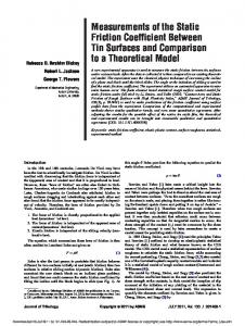
Static friction in the pulley was identified by “weight tray” tests in which we incrementally added known masses to a weight tray and then removed them while we measured the output of the force sensor. For the first set of tests, the force sensor was placed in a device specifically designed for its testing (Figure 4(a)), and in the second and third sets of tests (Figure 4(b)) and (c), the sensor was placed in a device specifically designed for testing force sensors (Figure 4(d)). This setup represents the orientation of the cable that produces the greatest normal force between the pulley and shaft and thus the greatest amount of friction between the two. By maximizing the friction at the pulley/shaft interface, we were able to fully demonstrate the effectiveness of the friction reduction technique.
333 FARRELL et al. Static friction and backlash effects on EPP-controlled protheses
Figure 4. Force sensor output voltage (Vf) vs. input force generated by weight-tray tests performed with force sensor placed in three different experimental setups: (a) results with force sensor mounted in force sensor-testing device. Results show nearly linear relationship with slight amount of hysteresis; (b) results with force sensor mounted on elbow with bearingless pulley. Note that when weights are being removed from weight tray, force that is registered by force sensor remains constant for almost an entire pound of input force; (c) results with force sensor mounted on elbow with ball-bearing pulley; and (d) schematic showing experimental setup used to obtain data shown in (b) and (c).
In the actual use of the elbow, the amount of friction that is present with a 5 lb load will vary with elbow angle. The amount of friction that is produced by a tensile force will be at a minimum when the elbow is in full extension because the force that is produced by the user will pull “up” on the pulley, while at the same time, this upward force will be coupled with a force applied by the cable between the pulley and the force sensor, pulling “down” on the pulley. These two forces will essentially
cancel. As the angle of elbow flexion increases, the angle between the force vectors that are produced by the tensile load will decrease, causing the sum of these forces on the pulley to increase and thus increase the amount of friction between the pulley and its shaft. Other factors that will affect whether or not the pulley will stick are the materials of the pulley and its shaft, as well as the tension in the control cable (as this force is increased, it will increase the normal force responsible for friction). In the
334 JRRD, Volume 42, Number 3, 2005
force sensor tester, the relationship between Vf (output voltage from the force sensor) and input force is nearly linear and possesses only a minimal amount of hysteresis (Figure 4(a)). When the force sensor was mounted on the elbow, the loading/unloading curve showed considerable hysteresis (Figure 4(b)). As the weights were unloaded from the weight tray, the input force was reduced initially by almost 1 lb, with no change in the output of the force sensor. Also, mounting the force sensor on the elbow caused the output of the force-sensor circuit to fail to reach 10 V when 5 lb of input force was applied (Figure 4(b)). Instead, the output voltage of the force sensor circuit reached its maximum at only 9 V, which is likely a result of the static friction in the pulley not allowing all of the input force to be transferred from the weight tray to the force sensor. To reduce static friction, we created a new pulley that contained an ABEC-5 ball bearing between the pulley and its axle. Figures 4(b) and (c) show weight tray tests on the system with the original pulley and with the ball bearing pulley, respectively. These experiments demonstrate that the ball-bearing pulley effectively removes the friction from this pulley/shaft interface. Eliminating the friction also causes the entire 5 lb of input force to again be presented to the force sensor, and thus the force sensor circuit registers an output of 10 V. Along with the previously mentioned static friction between the pulley and its shaft, some belt friction exists between the control cable and the pulley. However, this friction is not considered here because we conducted tests that showed that the friction between the cable and pulley was far greater than the friction between the pulley and its shaft. Therefore, the pulley will always slip on the shaft before the control cable will slip on the pulley. The method by which static friction causes limit cycles to develop in our EPP system can be explained if one considers the control cable to consist of one “spring” on either side of the pulley (Figure 5). The “forearm spring” represents the control cable between the pulley and the force sensor, and the “harness spring” represents the control cable between the elbow pulley and the harness (or in our experimental setup, the step-input board). The springs can be assumed to be made of the same material as the original control cable and thus possess the same modulus of elasticity. (Note: stiffness is a function of length but the modulus of elasticity is independent of length.) In this scenario, only the tension in the forearm spring acts as the input to the controller. Each subfigure in Figure 5 also contains a representation of Figure 2,
which shows the input force from the forearm spring at that moment in time. For one to understand the effect that friction has on an EPP system, it is useful to first consider the ideal response in the absence of friction. The elbow is considered to start at rest, as shown in Figure 5(a) with the elbow stationary because the input force lies within the parking band between Flow and Fhigh. With no friction in the pulley, the tension in the forearm spring will be equal to the tension in the harness spring. If the input point is moved a fixed distance away from the pulley, the tension is increased in both the harness and forearm springs, as shown in Figure 5(b). This increase in tension will cause the load on the force sensor to increase above Fhigh, the input force to the controller to enter the “flexion band,” and the elbow to flex. Elbow flexion will reduce the length of the forearm and harness “springs,” thus reducing the force sensor load until the input force falls back into the parking band, which will cause the elbow to stop moving. Alternatively, when the input point moves toward the pulley, the tension initially drops below Flow, but is returned to a value within the parking band as the elbow responds by extending. Although kinetic friction will undoubtedly play a role in this scenario, we chose to focus on the effects of static friction. Static friction was considered to be the worstcase scenario because the coefficient of static friction is usually much greater than the coefficient of kinetic friction. Static friction causes greater disparities between the tensions in the forearm and cable springs. Static friction also introduces the stick-slip phenomenon that is especially detrimental to EPP control. When we examine the step-input response of the system with static friction present, the tension in the forearm and harness springs is no longer necessarily equal. Again, we start with our system at rest as shown in Figure 5(a). As the input point is moved away from the pulley, the elbow will initially remain still with static friction present in the pulley. This is because the static friction at the pulley is not allowing the increase in tension in the harness spring to be transferred to the forearm spring/force sensor. After some amount of additional movement of the input point away from the pulley, the differences in tension of the harness and forearm “springs” will be greater than the amount of static friction, and the pulley will slip over its shaft. As soon as the pulley moves, the tension at the sensor increases into the flexion band and thus causes the elbow to begin moving (Figure 5(b)). If a large enough
335 FARRELL et al. Static friction and backlash effects on EPP-controlled protheses
Figure 5. Model demonstrating effects of static friction on system controlled by extended physiological proprioception. Control cable is modeled as a spring on either side of pulley. “Forearm spring” represents control cable between pulley and force sensor and “harness spring” represents control cable between elbow pulley and harness (or in our experimental setup, step-input board). In this scenario, only tension in forearm “spring” acts as input to controller. Each subfigure also contains a representation of Figure 2 to indicate within which controller band input lies: (a) shows system at rest. Note that input force lies within parking band; (b) step input is applied to system (note: input position has been moved away from pulley); tension produced in forearm spring causes controller to produce flexion command; (c) if friction in pulley holds the pulley’s position constant in relation to forearm as elbow flexes, harness spring will shorten and reduce its tension but forearm spring will not change length. Tension in forearm spring will continue to produce a flexion command; and (d) after pulley slips as a result of difference in tension in forearm and harness springs (note: lines on forearm and pulley are no longer aligned), forearm spring will shorten and apply a smaller force to force sensor that may be less than Flow and thus cause elbow to extend.
step input is applied, the difference in spring tensions will cause the pulley to slip almost immediately. Figure 5(b) represents a situation in which a step input has been applied to the system and has caused the tension in the forearm spring to be greater than the
threshold Fhigh, which causes the elbow to flex. It is assumed that the static friction between the pulley and its shaft does not initially allow the pulley to move, and because the pulley shaft is fixed to the forearm, the angular position of the pulley relative to the forearm remains
336 JRRD, Volume 42, Number 3, 2005
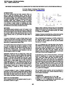
constant. Therefore, as the elbow flexes, the harness spring is able to shorten and decrease the amount of tension that it contains; however, the forearm spring is not allowed to shorten (Figure 5(c)). This causes the tension in the forearm spring to remain above the threshold Fhigh, and because only the tension in the forearm spring is the input to the controller, the elbow will continue to flex even though the tension in the harness spring may be within the parking or extension bands. As the elbow continues to flex and the harness spring continues to shorten, the difference in the tension contained in the harness and forearm springs increases. This difference in tension will exist until it becomes large enough to cause the pulley to overcome static friction, slip on the shaft, and move in relation to the forearm (Figure 5(d); note that the lines on the pulley and forearm are no longer aligned). After this slip, the forearm spring will shorten, and the tension in the forearm spring will be reduced. This reduced tension in the forearm may cause what was previously a flexion command to immediately convert into an extension command that will drive the elbow in the opposite direction. This same situation can occur in the opposite direction, resulting in alternating flexion and extension commands, producing a limit cycle. The effects of static friction in the pulley on the step response of an EPP system are shown in Figure 6. We can see that for a specific set of controller gains (the Fslack to Fmax range was approximately 1 lb), the system with the original high-friction pulley develops a limit cycle in each of a series of three step inputs (Figure 6(a)). Replacing the pulley with one that contains ball bearings eliminated the limit cycle (Figure 6(b)). During these experiments, the system’s backlash was reduced (as discussed in the following section) to ensure that these experiments focused solely on the effects of static friction. In the clinical implementation of EPP, static friction that exists at the pulley can be reduced in the same way it was here, with a pulley containing a ball bearing. Friction will also exist between the control cable and housing through which it is routed and can be reduced with Spectra® cable and a Teflon®-lined housing as described by Carlson et al. [20]. Even if static friction has no role in the control of the prosthesis, removing this friction is advantageous to allow for a strictly proportional relationship between the input from the user and the force presented at the force sensor. Removing static friction at the pulley improves the resolution in the force-feedback that the control cable provides which, in turn, produces an improved informa-
Figure 6. Series of three step responses for two similar systems except for pulley located at elbow. System in (a) has original pulley with no ball bearing, whereas (b) has pulley with ball bearing. When friction is reduced, limit cycles are eliminated.
tion exchange between the system’s input and output, i.e., the user and the elbow. Effect of Backlash on EPP Control Backlash was first thought to be an issue for EPP control when we observed that the forearm of the prosthesis could be moved while the position of the elbow motor was held stationary. Boston Elbows use a harmonic drive, and harmonic-drive gearing systems contain negligible amounts of backlash [21]. Thus, it was
337 FARRELL et al. Static friction and backlash effects on EPP-controlled protheses
unlikely that the observed backlash was a result of the motor/drive combination. We discovered that the primary source of backlash in the Boston Elbow I that we were using for this system was a result of the “free swing” option. The manufacturer provides a free swing option that allows the user to mechanically disengage the forearm from the motor drive to allow the arm to swing freely during walking. The observed backlash is a result of “play” in the pin used to lock the forearm to the motor-drive output of the elbow. We observed that this play is greatly reduced in later versions of the Boston Elbow. Although the amount of movement appears to be minimal (between 2° and 3°), this backlash has a significant effect when EPP control is used. Figure 7 shows how backlash could affect an EPP system. This schematic presents an exaggerated example of backlash in an EPP elbow. The control cable is modeled as a single spring with both ends fixed. As the position of the forearm is moved from one extreme of the backlash zone (position Ψ in Figure 7(a)) to the other extreme of the backlash zone (position Ψ in Figure 7(b)), the control cable spring is stretched. The relationship between the position of the forearm and the change in length of the spring is expressed by ∆X = R pulley × ( ∆Ψ ) × π/180 ,
(1)
where ∆X = the linear excursion of the spring ,
∆Ψ = the angular magnitude of the backlash ( in degrees ) ,
and R pulley = radius of a pulley about which the cable is wrapped .
As the forearm moves through the backlash zone, the control cable will be stretched or relaxed depending on the direction of movement. When the control cable is stretched, tension in the cable increases; therefore, an increased force is presented to the force sensor on the forearm. The change in force that is presented at the force sensor as the forearm passes through the backlash can be determined by Equation (2), which is simply Hooke’s Law: ∆F f = K cable × ∆X , where ∆F f = change in force at the force sensor, and
(2)
Figure 7. Schematics demonstrating how backlash affects extended physiological proprioception system. As forearm moves through an exaggerated backlash zone (from (a) to (b)), control cable, which is modeled as a spring, is stretched, and force at force sensor is increased.
K cable = the spring constant of the control cable . These two equations predict that reducing the amount of backlash in the system will reduce the change in input force that is created as the forearm passes through the backlash zone. By itself, Equation (2) also predicts that if the system contains a given amount of backlash, decreasing the spring constant of the control cable will reduce the change in force presented to the force sensor
338 JRRD, Volume 42, Number 3, 2005
as the forearm passes through this backlash. We conducted experiments to demonstrate that reducing the spring constant of the control cable did, in fact, eliminate the development of limit cycles. However, this solution is viewed as non-ideal because it reduces the coupling between the user and the prosthesis that is so important to the feedback that EPP provides. We conducted an experiment to determine the potential change in tension in the control cable as the forearm moves through the backlash zone. A step input was applied to the system and held, and then the forearm was cycled manually from one end of the backlash zone to the other. The angular magnitude of the backlash was approximately 2.5°, and the measured input force varied by approximately 1.25 lb. The controller input ranges from 0 lb to 5 lb; thus, the 1.25 lb change in input force that was observed in this experiment represents 25 percent of the input range of the system. In many of the controllers that have been used, a change of 1 lb of force could span several of the bands (e.g., full flexion, flexion, parking band, etc.) of the controller (Figure 2). Even though this 1 lb change in input force was produced manually, something similar will likely occur in the actual use of the elbow. The mass (450 g) located at the end of the forearm will likely give the forearm enough inertia to move through the backlash zone. It was observed experimentally that reducing the mass at the distal end of the forearm reduced the likelihood of limitcycle development. To bypass the forearm free-swing element, we modified the plate on which the EPP pulley is mounted to attach the forearm directly to the motor drive. Although these modifications did not remove all of the backlash present in the system, they greatly reduced the backlash magnitude. The previously described experiment of manually cycling the elbow through the backlash was repeated. The modifications reduced the amount of backlash from 2.5° to less than 0.5°. The magnitude of the change in force was reduced to approximately 0.25 lb. For a particular controller profile (Figure 2), we presented a series of step inputs to both the unmodified Boston Elbow system and the modified, reduced-backlash system. To ensure that only the effects of backlash were being investigated during these experiments, we used the ball-bearing pulley to eliminate the previously discussed effects of static friction. The resultant step response of the unmodified elbow and the position data for the sys-
tem in which the backlash was reduced are shown in Figure 8(a) and (b), respectively. A small amount of drift can be seen to exist during these trials. Although we hypothesize that this is a result of the Dacron control cable being stretched after repeated cycles and increasing in length, we do not have any specific evidence to support this claim. We can demonstrate the negative effect of the presence of backlash on EPP control by comparing the step responses. For a particular controller profile, reducing the backlash of the system eliminated the limit cycle. However,
Figure 8. Series of three step responses for two systems with different amounts of backlash. System in (a) has original, large amount of backlash, whereas (b) shows step-input responses for reduced backlash system. When system’s backlash is reduced, limit cycles are eliminated.
339 FARRELL et al. Static friction and backlash effects on EPP-controlled protheses
since some backlash still remains in the system, it is still possible to increase the gains of the controller to reintroduce the limit cycle to the system that has the reduced backlash. Although one particular elbow was examined in this study, we also observed that other powered elbows also contain backlash, such as the Utah Arm (Motion Control, Salt Lake City, UT) and NY Electric Elbow (Hosmer Dorrance Corporation, Campbell, CA). We have shown that backlash in the elbow can contribute to the development of limit cycles and therefore EPP control would benefit from the removal of all backlash from the powered-elbow systems on which it is implemented. However, individual prosthetists may have difficulty removing this backlash without manufacturer assistance. Therefore, we suggest that components be selected that possess minimal amounts of backlash for the clinical implementation of EPP.
DISCUSSION The suggestion that static friction and backlash are undesirable properties and induce unwanted effects on the control of many types of devices is not a novel one. In fact, the effects of friction and backlash on the development of limit cycles and methods of compensating for these effects have been studied widely in robotics and other related fields [22–28]. However, backlash and friction have not been considered to be significant problems in the field of prosthetics. A high-performance device in prosthetics usually refers to a device that can produce high torques and angular velocities, not necessarily devices that contain small amounts of friction and backlash. Because of the asymmetric contribution of gravity on this system, we mounted the elbow on its side to eliminate the effects of gravity. This facilitated identifying the issues involved in the development of limit cycles. However, in typical use, the elbow will be in an upright position in which gravity will be working “with” the mass of the prehensor as the elbow extends and “against” it as the elbow flexes. Further experiments found that, as with the elbow mounted on its side, removing the backlash and friction from the system makes eliminating the limit cycle possible when the elbow is operated in the upright position [18]. The results of our work also can be applied to other devices in which the human operator is connected directly to the output of the device being operated. Examples of such devices are “extender” robots [29–30], power-assisted manual wheelchairs, and haptic manipu-
lators. Wheelchairs such as the e.motion (Frank Mobility Systems, Inc., Oakdale, PA); iGLIDE (Independence Technology, Warren, NJ); and the Quickie Xtender (Sunrise Medical, Longmont, CO) are designed to provide external power assistance to manual wheelchair users. The chairs function with the use of a measurement of the force that the user produces on the hand rims to calculate the magnitude and direction of movement assistance. These sensors measure the input force through either torque or linear force measurement. Clinicians have observed that these systems tend to oscillate, especially when the user is trying to maneuver in tight spaces.* Backlash was observed to exist in the power-assist mechanism of one of the chairs mentioned above, and it can be hypothesized, based on our work, that reducing the backlash in this system might eliminate the oscillations.
CONCLUSIONS This work was driven by a need to eliminate the “jerky” behavior that was seen in previous clinical applications and indicate to prosthetists and component designers the factors that would affect the performance of EPP-controlled prostheses. We found that two of the many nonlinearities that exist in this system cause the tension in the control cable to vary from what was expected. These variations in control-cable tension cause alternating flexion and extension inputs to be applied to the system and thus cause the system to develop a limit cycle. We found that the backlash and static friction that exist in the system are primarily responsible for the development of the limit cycle in the step response of the system. We also found that the magnitude of the effect that the backlash had on the system was determined by the stiffness of the control cable as well as the mass located at the distal end of the forearm. We demonstrated that reducing the static friction and the backlash in the system could prevent the limit cycle. Therefore, prosthetic components should be selected that minimize both backlash and static friction when EPP control is being implemented. Finally, although one does not have a good deal of flexibility in selecting the prehensor, because a large mass at the distal
*Personal
communication with Rory Cooper; Chairman and Professor of the Department of Rehabilitation Science and Technology, University of Pittsburgh; 29 July 2003.
340 JRRD, Volume 42, Number 3, 2005
end of the forearm was shown to contribute to undesired behavior, prehensor weight should be kept to a minimum.
REFERENCES 1. Soede M. Mental control load and acceptance of arm prosthesis. Automedica. 1982;4:183–91. 2. Doubler JA, Childress DS. An analysis of extended physiological proprioception as a prosthesis-control technique. J Rehabil Res Dev. 1984;21(1):5–18. 3. Simpson DC. The choice of control system for the multimovement prosthesis: extended physiological proprioception. In: Herberts P, Kadefors R, Magnusson RI, Petersen I, editors. The control of upper-extremity prostheses and orthoses. Springfield (MA): C.C. Thomas; 1974. p. 146–50. 4. Simpson DC. An externally powered prosthesis for the complete arm. Biomed Eng. 1969;4(3):106–10. 5. Simpson DC, Kenworthy G. The design of a complete arm prosthesis. Biomed Eng. 1973;8(2):56–59. 6. Weir RF. Direct muscle attachment as a control input for a position-servo prosthesis controller [dissertation]. Evanston (IL): Northwestern University, Department of Biomedical Engineering; 1995. 7. Al-Angari HM, Weir RF, Heckathorne CW, Childress DS. A two degree-of-freedom microprocessor based extended physiological proprioception (EPP) controller for upper limb prostheses. Technol Disabil. 2003;15(2):113–27. 8. Weir RF, Heckathorne CW, Childress DS. Cineplasty as a control input for externally powered prosthetic components. J Rehabil Res Dev. 2001;38(4):357–63. 9. Van der Linde RQ, Lammertse P, Frederiksen E, Ruiter B. The HapticMaster, a new high-performance Haptic interface. Proceedings Eurohaptics; 2002 Jul 8–10; Edinburgh (UK); 2002. p. 1–5. 10. Doubler JA, Childress DS. Design and evaluation of a prosthesis control system based on the concept of extended physiological proprioception. J Rehabil Res Dev. 1984;21(1): 19–31. 11. Heckathorne CW, Philipson L, Hermansson L, Childress DS. Extended physiological proprioception for children’s electrical prostheses. In: Zupko J, editor. Proceedings of the 7th World Congress of the International Society for Prosthetics and Orthotics (ISPO); 1992 Jun 28–Jul 3. Chicago (IL). Arlington (VA): ISPO Publications; 1992. p. 317. 12. Heckathorne CW, Uellendahl J, Childress DS. Application of a force-actuated position-servo controller for electric elbows. In: Zupko J, editor. Proceedings of the 7th World Congress of the International Society for Prosthetics and Orthotics (ISPO); 1992 Jun 28–Jul 3. Chicago (IL). Arlington (VA): ISPO Publications; 1992. p. 315.
13. Heckathorne CW, Strysik JS, Grahn EC. Design of a modular extended physiological proprioception controller for clinical applications in prosthesis control. In: Presperin J, editor. Proceedings of the 12th Annual RESNA Conference, 1989 Jun 25–30; New Orleans (LA). Washington (DC): RESNA Press; 1989. p. 226–27. 14. Bertos YA, Heckathorne CW, Weir RF, Childress DS. Microprocessor based E.P.P. position controller for electricpowered upper limb prostheses. Proceedings of the 19th Annual International Conference of the IEEE-EMB Society; 1997 Oct 30–Nov 2; Chicago (IL). New York: Institute of Electrical and Electronics Engineers; 1997. p. 2311–14. 15. Al-Angari HM. A Design of two degrees of freedom microprocessor-based E.P.P. position controller for upperlimb prostheses [master’s thesis]. Evanston (IL): Northwestern University, Department of Biomedical Engineering; 2001. 16. Doering JE. Modeling of the Michigan Arm to explain limit cycle behavior [master’s thesis]. Evanston (IL): Northwestern University, Department of Mechanical Engineering; 2001. 17. Nayfeh AH, Mook DT. Nonlinear oscillations. New York: John Wiley and Sons; 1979. p. 6,103–7. 18. Farrell TR. The effect of non-linearities on extended physiological proprioception (EPP) control of a powered prosthesis. [master’s thesis]. Evanston (IL): Northwestern University, Department of Biomedical Engineering; 2003. 19. Heckathorne CW. Components for adult externally powered systems. In: Bowker JH, Michael JW, editors. Atlas of limb prosthetics: surgical, prosthetic and rehabilitation principles. 2nd ed., chapter 6C. St. Louis (MO): MosbyYear Book, Inc. 1992. p. 151–74. 20. Carlson LE, Veatch BD, Frey DD. Efficiency of prosthetic cable and housing. J Prosthet Orthot. 1995;7(3):96–99. 21. Kircanski NM, Goldenberg AA. An experimental study of nonlinear stiffness, hysteresis, and friction effects in robot joints with harmonic drives and torque sensors. Int J Robotics Res. 1997;16(2):214–39. 22. Boneh R, Yaniv O. Reduction of limit cycle amplitude in the presence of backlash. J Dyn Syst Meas Control. Jun 1999;121:278–84. 23. Tustin A. The effects of backlash and of speed-dependent friction on the stability of closed-cycle control systems. J IEE (London). 1947;94(II):143–51. 24. Armstrong-Helvouvry B, DuPont P, Canudas De Wit C. A Survey of models, analysis tools and compensation methods for the control of machines with friction. Automatica. 1994; 30(7):1083–138. 25. Radcliffe CJ, Southward SC. A property of stick-slip friction models which promotes limit cycle generation. Proceedings of the 1990 American Control Conference, American Control
341 FARRELL et al. Static friction and backlash effects on EPP-controlled protheses
Council; 1990 May 23–25; San Diego (CA). Green Valley (AZ): American Control Council; 1990. p. 1198–203. 26. Wang Y, Longman RW. Limit cycle behavior and convergence to zero error in learning control with stick-slip friction. IEEE International Conference on Systems, Man, and Cybernetics: Humans, Information, and Technology; 1994 Oct 2–5; San Antonio (TX). New York: Institute of Electrical and Electronics Engineers; 1994. p. 2774–79. 27. Yang S, Tomizuka M. Adaptive pulse-width control for precise positioning under influence of stiction and coulomb friction. Proceedings of the 1987 American Control Conference; 1987 Jun 10–12; Minneapolis (MN). Green Valley (AZ): American Control Council; 1987. p. 188–93. 28. Azenha A, Machado JT. Limit cycle prediction of robot systems with nonlinear phenomena in the joints. 27th International Symposium on Industrial Robots; Milan, Italy; 1996. p. 1003–8.
29. Kazerooni H. Human machine interaction via the transfer of power and information signals; Part I: Fundamentals. In: Youcef-Toumi K, Kazerooni H, editors. Proceedings of the AMCE Winter Annual Meeting; 1988 Nov 28–Dec 2; Chicago (IL). New York: American Society of Mechanical Engineers; 1988. p. 149–61. 30. Kazerooni H. Human machine interaction via the transfer of power and information signals; Part II: Dynamics and control analysis. In: Youcef-Toumi K, Kazerooni H, editors. Proceedings of the AMCE Winter Annual Meeting; 1988 Nov 28–Dec 2; Chicago (IL). New York: American Society of Mechanical Engineers; 1988. p. 163–75.
Submitted for publication on May 7, 2004. Accepted in revised form November 2, 2004.