Oct 5, 2011 - tor temperature (temperature below the boiling point of H2O). Flat-plate collectors can .... lithium bromide absorption cooling cycle. The detailed ...
This article was downloaded by: [Hanyang University] On: 12 September 2012, At: 21:14 Publisher: Taylor & Francis Informa Ltd Registered in England and Wales Registered Number: 1072954 Registered office: Mortimer House, 37-41 Mortimer Street, London W1T 3JH, UK
Heat Transfer Engineering Publication details, including instructions for authors and subscription information: http://www.tandfonline.com/loi/uhte20
The Influence of Collector Fluid Inlet Temperature on the Performance of a Solar-Assisted Absorption System Using Step-Finned Flat-Plate Collector Balaram Kundu a
a
Department of Mechanical Engineering, Jadavpur University, Kolkata, India
Version of record first published: 05 Oct 2011.
To cite this article: Balaram Kundu (2007): The Influence of Collector Fluid Inlet Temperature on the Performance of a SolarAssisted Absorption System Using Step-Finned Flat-Plate Collector, Heat Transfer Engineering, 28:5, 496-505 To link to this article: http://dx.doi.org/10.1080/01457630601166150
PLEASE SCROLL DOWN FOR ARTICLE Full terms and conditions of use: http://www.tandfonline.com/page/terms-and-conditions This article may be used for research, teaching, and private study purposes. Any substantial or systematic reproduction, redistribution, reselling, loan, sub-licensing, systematic supply, or distribution in any form to anyone is expressly forbidden. The publisher does not give any warranty express or implied or make any representation that the contents will be complete or accurate or up to date. The accuracy of any instructions, formulae, and drug doses should be independently verified with primary sources. The publisher shall not be liable for any loss, actions, claims, proceedings, demand, or costs or damages whatsoever or howsoever caused arising directly or indirectly in connection with or arising out of the use of this material.
Heat Transfer Engineering, 28(5):496–505, 2007 C Taylor and Francis Group, LLC Copyright � ISSN: 0145-7632 print / 1521-0537 online DOI: 10.1080/01457630601166150
Downloaded by [Hanyang University] at 21:14 12 September 2012
The Influence of Collector Fluid Inlet Temperature on the Performance of a Solar-Assisted Absorption System Using Step-Finned Flat-Plate Collector BALARAM KUNDU Department of Mechanical Engineering, Jadavpur University, Kolkata, India
In the present work, an extensive analysis is developed for an evaluation of the thermal performance of a solar-powered H2 O/LiBr absorption cooling system using a step-fin flat-plate collector (SFC). The performance parameters, namely, collector efficiency factor, heat removal factor, and collector efficiency, for the SFC is derived. A system simulation model has been developed to analyze the system performance—that is, to identify an operating criterion as a function of the collector fluid inlet temperature (TFI ). It has been observed from the results that the performance of the system depends strongly on TFI . Simulation results show that the system operates optimally (maximum coefficient of performance) at an optimal TFI . When the system runs at this optimal value of TFI , minimum collector material is required. Thus, when using SFC in place of a rectangular-fin flat-collector, thirty-five percent or more collector material can be saved. However, it has been observed that the effect of thermal conductivity on the plate volume of SFC has a marginal effect.
INTRODUCTION Cooling with the use of solar energy has become more attractive due to the critical shortage of fossil fuels in recent years. Because the demand for cooling is generally greatest at the time of strongest sunshine, the seasonable variation of terrestrial insulation meshes very well with the need for cooling to provide human comfort and food preservation. Furthermore, solar cooling systems have been most commonly employed in rural areas where there is no firm electricity to supply conventional power systems. These may be the primary motivating factors in the continuing development of solar cooling system. The solar-operated system differs from a customary fossil fuel-fired unit in that the energy supplied to the generator is from a solar collector. The most promising application to produce cooling by using solar energy is the vapor absorption system due to its simple operation and ability to utilize low-grade thermal energy.
Address correspondence to Dr. B. Kundu, Department of Mechanical Engineering, Jadavpur University, Kolkata, India. E-mail: bkundu123@ rediffmail.com
There are two approaches used for the solar operation of absorption coolers. The first approach is to consider a continuous cooler with energy supplied to the generator from the solar collector storage auxiliary system, and the second is to use an intermittent cooler. Flat-plate collectors are generally adapted to the operation of continuous absorption cycles. A water-lithium bromide (H2 O/LiBr) absorption system requires a low generator temperature (temperature below the boiling point of H2 O). Flat-plate collectors can meet this requirement. In addition, a flat-plate collector is the simplest means for converting solar energy into useful heat for heating up the generator. Because of the compatibility of the absorption system with the low-grade heat generated by flat-plate solar collectors, its application tends to gradually increase. Also, due to its use of water as a refrigerant instead of CFC and HCFC, the H2 O/LiBr absorption system becomes very attractive. To increase the thermal conductivity in solar collector, a metallic solar collector with fins is used. The performance of solar-assisted absorption cooling systems depends on the performance of both solar collectors and absorption systems. This performance is measured on an instantaneous basis and with the performance integrated over full days of operation.
496
Downloaded by [Hanyang University] at 21:14 12 September 2012
B. KUNDU
Different profile shapes (i.e., straight rectangular, rectangular with a step change in local thickness, straight trapezoidal, straight triangular, and straight of inverse parabolic) have been used for the design of flat-plate collectors by several researchers [1–3]. Kowalski and Foster [4] developed a general methodology for the design of a flat-plate solar collector based on solar collector theory. Riffat et al. [5] presented the performance testing of different types of liquid flat-plate collectors. Al-nimr et al. [6] derived an expression for the size optimization of a flat-plate collector that maximizes the life cycle savings of the collector. Lund [7] investigated a general thermal analysis of parallel flow flat-plate solar collector absorbers. For the thermal analysis of an absorber plate, he solved a two-dimensional heat conduction equation numerically. Many researchers [8–10] have also studied solar power absorption cooling systems. Using thermodynamic analysis, Mansoori and Patel [11] determined different refrigerantabsorbent combinations and developed a technique for the comparative evaluation of NH3 +H2 O, NH3 +NaSCN, and H2 O+LiBr combinations, which are favorable candidates for solar absorption cooling cycles. Li and Sumathy [12] presented the simulation of a solar-powered absorption system with the absorption pair of LiBr/H2 O. Xu et al. [13] studied the thermodynamic analysis for H2 O-LiBr absorption chiller. They investigated the effect of design parameters on the performance of a double effect absorption chiller. Sabir and Eames [14] analyzed a theoretical comparison between the performance of a LiBr-H2 O resorption and absorption cycles. They observed that at a low chilled water temperature, the relative improvement of the resorption cycle is more significant. Florides et al. [15] have given a method for evaluating the characteristics and performance of a single stage LiBr-H2 O absorption machine. The adiabatic absorption of water vapor into LiBr-H2 O solutions has been studied experimentally by Arzoz et al. [16]. Of the profile shapes mentioned previously (namely, rectangular, trapezoidal, triangular, parabolic, and hyperbolic), only a few are compatible with the collector design. Due to the simplicity and ease of fabrication, a straight rectangular profile is mostly found for the design of flat-plate collectors. In order to ensure the conservation of material for flat-plate collectors, a step-fin flat-plate collector (SFC) may be used. First, an investigation of this type of profile was proposed by Hollands and Stedman [1]. Their work was mainly concentrated on the determination of the fin efficiency. Later, Kundu [3] modified the work of Hollands and Stedman [1] and developed a generalized methodology to determine the optimum fin dimensions. A review of the literature reveals that the past work in solarpowered cooling systems were concerned mainly with the thermal analysis of SFCs and thermodynamic analysis of absorption cooling systems separately. However, in actual practice, energy is absorbed on the flat-plate solar collector, which is supplied to the generator of a solar-operated vapor absorption cooling system. Thus, a conjugate analysis of solar collector and vapor absorption system is needed to predict the overall system performance and optimum design condition. Furthermore, researchers heat transfer engineering
497
have rarely concentrated on the analysis of absorption system using SFC. But it is found in literature [1, 3] that SFC is the better choice for transferring heat per unit volume compared to the rectangular-fin flat-plate collector (RFC). In comparison with variable thickness fin flat-plate collectors, SFC is relatively easy to manufacture and hence less expensive. The present study deals analytically with the effect of collector fluid inlet temperature (T FI ) on the instantaneous overall performance of solar-operated H2 O/LiBr systems using SFC. To determine the collector performance factors (i.e., the collector efficiency factor, heat removal factor, and instantaneous collector efficiency of SFCs), an analytical model is established. The results are presented systematically to show the effect of T FI . A significant effect on system performances has been noticed. For a specified design, the maximum coefficient of performance (COP) of the system has been obtained at an optimal value of T FI . This temperature may be called the operational fluid-inlet temperature. If the system runs at this T FI , minimum plate material is required. A scheme has been developed to compare the relative amount of plate material required for a SFC and a RFC for the same design variables and desired effect. Finally, influences of thermal conductivity and ambient temperature on the plate volume have been carried out.
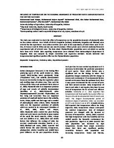
ANALYSIS A solar-powered absorption cooling system basically consists of a solar collector, a generator, a condenser, an evaporator, an absorber, an economizer, and two pressure reducing valves. Figure 1 shows the flow diagram of a solar-powered H2 O/LiBr absorption cooling system. The necessary heat is supplied to the generator by using a SFC. The solar-powered H2 O/LiBr cooling
Figure 1 system.
Flow diagram for solar-powered H2 O/LiBr absorption cooling
vol. 28 no. 5 2007
498
B. KUNDU
Beside the heat transferred through the fin, heat is also collected above the tube region. Therefore, the useful heat gain per unit length in the direction of fluid flow qU is given by qU = kC (H A /UC + T AM − TB ) � � × 2ψZ 02 η F {1 + ψ(1 − p)} + Bi1
Downloaded by [Hanyang University] at 21:14 12 September 2012
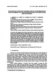
Figure 2 A schematic diagram of a SFC.
system using an SFC is the combination of thermal analysis of flat-plate collectors and thermodynamic analysis of waterlithium bromide absorption cooling cycle. The detailed analysis of the system is given below.
Thermal Analysis of Flat-Plate Collector Solar energy collectors are special kinds of heat exchangers that transform solar radiant energy into the transport medium. A flat-plate collector has the same area of intercepting for absorption of solar radiation. A typical SFC is shown diagrammatically in Figure 2. The maximum plate temperature occurs at the midpoint between the two tubes, meaning that there is no heat transfer across the section. The temperature of the plate at the tube bond (TB ) is considered a constant, and solar energy is also absorbed at the excess plate thickness of the junction of two parts. Under steady-state conditions, the energy balance for an SFC per unit length in the direction of fluid flow is made to evaluate the temperature distribution. For the consideration of the above statements, the temperature distribution in SFCs has already been determined by Kundu [3], taking into account that the values of H A and U C have been used as arbitrary constants. However, these two parameters depend usually on the location, time, and design conditions of the absorber plate. Thus, these effects have been included in the present study. Due to scarcity of space, the detailed procedures for calculation of the fin efficiency of SFCs can be found elsewhere [3]. However, to determine the collector performance factors of an SFC (i.e., collector efficiency factor, heat removal factor, and instantaneous collector efficiency), it is necessary to formulate the following mathematical expressions. The fin efficiency for SFC [3] can be expressed in the following equations: ηF = where Z0 =
√
The useful heat gain must be transferred to the collector fluid in the tube. In terms of the thermal resistance encountered in the transfer of heat from temperature TB to TF , the useful heat gain qU can be written as � � qU = kC η�F 2ψ Z 02 {1 + (1 − p) ψ} + Bi1 × [(H A /UC ) + T AM − TF ]
ψ = tC /L 1 , X 0 = x0 /L 1 and p = t1 /tC heat transfer engineering
(3)
where the collector efficiency factor η�F can be expressed as � 2 ψ Z 02 {1 + (1 − p) ψ} + Bi1 ]−1 � ηF = (4) 1 0 /d I ) + CkCB + kC ln(d + π hkCL d I 2π k T 2ψ Z 2 η [1+ψ (1− p)]+Bi 0
F
1
Equation (4) gives the useful energy gain per unit flow length of the collector fluid, water, in a tube. The fluid temperature increases in the direction of flow due to the transfer of thermal energy into the tube. Under steady-state conditions, from the energy balance, the increase of fluid temperature in the direction of flow can be expressed as TFO − TFI = [(H A /UC ) + TAM − TFI ] � � �� −AC UC η�F × 1 − exp m W CPW
(5)
where AC is the aperture-area of the absorber plate on which the solar energy is absorbed: AC = L 2 N [2L 1 + 2tC (1 − p) + d0 ]
(6)
From Eqs. (3) and (5), the total useful energy gain by the collector to the working fluid can be obtained from the following expressions: � FR AC [H A − UC (TFI − TAM ) ] qUT = (7) AC [H A − UC (TPM − TAM ) ] where TPM and FR are the mean temperature and heat removal factor of a collector, respectively. The heat removal factor can
√ [1 + ψ (1 − p) ]−1 [ ψ Z 0 (1 − p) + p tanh Z 1 + tanh{Z 0 (1 − X 0 ) } ] √ Z 0 [ 1 + ψ Z 0 (1 − p) tanh {Z 0 (1 − X 0 ) } + p tanh Z 1 tanh {Z 0 (1 − X 0 ) } ]
√ Bi/ψ, Z 1 = Z 0 X 0 / p, Bi = UC tC /kC ,
(2)
be expressed symbolically as
�
� AC UC η�F m W CPW 1 − exp − FR = A C UC m W CPW vol. 28 no. 5 2007
(1)
(8)
B. KUNDU
The mean temperature of the absorber plate can be found by solving Eq. (7): TPM = TFI + qUT (1 − FR )/(AC UC FR )
(9)
The instantaneous efficiency of a solar collector is given by
Downloaded by [Hanyang University] at 21:14 12 September 2012
ηC = qUT /(AC HT )
(10)
The detailed procedure for the determination of total incident flux, HT , absorbed solar flux, H A , and the overall loss coefficient, UC , can be found elsewhere [8, 17]. The sky temperature is taken as TAM − 6 [8]. In this section, it may be noted that for the calculation of H A , the effective absorptance and emittance of the SFC are considered. It is worthy to mention that the large scale roughness of the absorber plate can produce selective surface characteristics and improve the solar collector performance. In this section, it can be mentioned that the present analysis is also valid for an RFC considering only X 0 = 0.
499
cycle: h 2 = h 3 , h 5 = h 6 and h 9 = h 10
The state points of rich and weak H2 O/LiBr solutions after passing through the economizer can be calculated as follows: ⎡ ⎤ ⎡ ⎤ qMAX1 m P (h 7MAX − h 6 ) ⎢q ⎥ ⎣ (15) ⎣ MAX2 ⎦ = (m P − m EVA ) (h 8 − h 9MIN ) ⎦ MIN { qMAX1 , qMAX2 } qMAX where h 7MAX and h 9MIN are the possible maximum and the minimum specific enthalpy of rich and weak refrigerant solutions, respectively, and qMAX is the maximum possible heat transfer in the economizer. The actual heat transfer in the economizer qECO can be determined if the above equation is multiplied by the effectiveness of the economizer εECO : qECO = qMAX × εECO
Cycle Analysis of a Water-Lithium Bromide Absorption System A detailed cycle analysis of H2 O-LiBr absorption system can be found elsewhere [11]. Therefore, only a brief analysis of it will be presented here to help in the understanding of the present study of the absorption cycle with the consideration of an economizer. The overall COP of a solar absorption cooling system can be expressed from the following: � qEVA /(AC HT ) (COP)SYS = (11) (COP)CYC × ηC According to the first law of thermodynamics for flow systems in a steady-state absorption cycle, the following relations are derived between the heat and the properties of the working fluids using the state points taken according to Figure 1: ⎡ ⎤ ⎡ ⎤ qGEN m EVA (h 1 − h 8 ) + m P (h 8 − h 7 ) ⎢ ⎥ ⎢ qCON ⎥ ⎢ m EVA (h 1 − h 2 ) ⎥ ⎢ ⎥ ⎢ ⎥ (12) ⎢ qEVA ⎥ = ⎣ m EVA (h 4 − h 3 ) ⎦ ⎣ ⎦ m EVA (h 4 − h 10 ) + m P (h 10 − h 5 ) qABS In the above equations, h is the specific enthalpy, m EVA the mass flow rate of refrigerant passing through the evaporator, and m P the mass flow rate of rich aqueous solution passing through the liquid pump. The following relation between m EVA and m P can be expressed as m P /m EVA = (1 − X GEN )/(X ABS − X GEN )
(13)
where X ABS is the mass fraction of water in the strong H2 O/LiBr solution coming out from the absorber and X GEN the mass fraction of water in the weak liquid H2 O/LiBr solution coming out from the generator. The following relations are obtained for the throttling processes and for assumption of the negligible pump work in the heat transfer engineering
(14)
(16)
After getting the value of qECO , state points 7 and 9 (Figure 1) can readily be calculated. Based on the above analysis, the COP of the cycle is estimated and the cooling efficiencies of cycle and system can be defined as � � � � (ηCO )CYC (COP)CYC /(C O P)CAR = (17) (ηCO )SYS (COP)SYS /(C O P)CAR Analysis of Solar-Operated Water-Lithium Bromide Absorption System From Eq. (7), it can be seen that the useful energy gain by the collector is a function of the collector area, the overall loss coefficient, the absorbed solar flux, and the inlet temperature of collector fluid when the other thermo-geometrical parameters are kept constant. In this study, water is used as a collector fluid that carries the solar energy for heating the generator. To analyze the H2 O/LiBr solar absorption system, the following procedures are used. From the energy balance, the heat supply to the generator is equal to the heat gain by the collector under a steady-state condition. Thus, the generator temperature can be obtained from the following expressions for a given inlet temperature of collector fluid T FI and effectiveness of a generator εGEN : TGEN = TFI + qGEN /(CMIN εGEN )
(18)
where the CMIN is a smaller of (m W CPW ) and (m P CPR ). Equation (18) shows that the generator temperature is an implicit function. So, to determine a generator temperature, an iterative scheme has been developed. The following steps can be followed to solve the generator temperature. Assuming a generator temperature for a specified value of the condenser, absorber, evaporator and collector fluid inlet temperatures, all the state points in the cycle, mass flow rate of rich vol. 28 no. 5 2007
Downloaded by [Hanyang University] at 21:14 12 September 2012
500
B. KUNDU
H2 O/LiBr solution, and heat supplied to the generator can readily be derived with the help of Eqs. (12–16). Next, substituting the required parameters in Eq. (18), the temperature of the generator is obtained from the first iteration. If the assumed and computed values of the generator temperatures are different, it is necessary to repeat the calculations until a specified convergence (10−8 ) is achieved. After evaluating the generator temperature and heat exchange rate in the generator, the following essential steps are used for the determination of the overall loss coefficient, the collector surface area, and the plate volume of the collector. For the same T FI and qGEN (a value equal to the heat gain by the collector) taken from the previous step and also a guess value of plate mean temperature TPM and surface area AC , the collector loss coefficient (UC ) and the rate of useful energy gain by the collector has been calculated. Next, the plate mean temperature is obtained from Eq. (9). The collector area is also determined from Eq. (7) by substituting the rate of useful energy gain qGEN . If the computed mean plate temperature and collector aperture area are different from the assumed values, the calculation can be repeated until a specified convergence (10−8 ) is reached. With this computed value of AC , the plate volume of the absorber plate can readily be determined from the following expression: � � kC ψ2 Z 02 AC 2 ψ Z 02 + Bi1 − 2 (1 − p) X 0 ψ Z 02 � � V = (19) UC 2ψ Z 02 + Bi1 − 2 (1 − p) ψ2 Z 02 RESULTS AND DISCUSSION The above analysis clearly shows that the system performance is a function of the inlet temperature of the collector fluid for other given thermo-geometrical parameters and also for a desired design application. Therefore, a scheme has been developed to simulate the results with the variation of the inlet temperature of the collector fluid. In the absorption cycle, the generator and the economizer facilitate heat transfer between two fluids (collector fluid and H2 O/LiBr solution) acting as a counterflow heat exchanger. For the transfer of heat, the effectiveness of the generator and the economizer is considered to be 0.85 separately. It is well known that for a given generator temperature, the increase of the cycle COP in any absorption systems can be made by raising the evaporator temperature as well as by reducing the condenser and absorber temperatures. Although the condenser and the absorber temperatures depend mainly on the ambient temperature, the designer fixes the evaporator temperature depending upon a particular application. Therefore, the generator temperature is the only variable. This generator temperature is inherently related to the collector fluid inlet temperature (T FI ). On that basis, the result of the present study is executed for constant condenser, absorber, and evaporator temperatures (TCON = 34◦ C, TABS = 30◦ C, TEVA = 6◦ C) and 1 ton evaporator capacity. However, for the selection of the evaporator heat transfer engineering
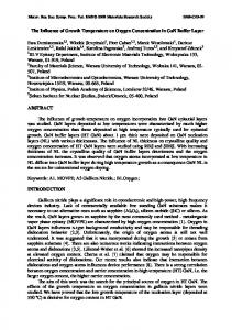
temperature, caution has to be taken: as water is the refrigerant in the H2 O/LiBr absorption system, the evaporator temperature should be kept above the freezing point to avoid the formation of ice in the evaporator. The steady-state results in this simulation have been taken for the location in Kolkata (22◦ 39� N, 88◦ 27� E) on June 10 at 11:00 hours (IST). The present study is also applicable for any place on any date at any solar time in the world. The following data are taken for the calculation of HT , H A and UC as follows: wind side heat transfer coefficient = 10 W/m2 K, extinction coefficient of the glass cover = 10 m−1 , number of glass cover = 2, tilt angle = 20◦ , thickness of the glass cover = 0.0023 m, emissivity of glass = 0.9, emissivity of the collector plate = 0.1, diffuse reflectivity of the ground = 0.2, thickness of the bottom insulation of the collector = 0.05 m, thermal conductivity of the bottom insulation = 0.045 W/mK, and edge loss coefficient of the collector based on the perimeter area = 0.5 W/m2 K. To establish the validity of the present study, it is necessary to compare it with the existing available results in the literature. Unfortunately, it is not possible to execute it directly due to the unavailability of results in the direction of the present parametric study. The solar-operated absorption cooling system consists of two individual analyses. However, most of the research has rarely attempted to analyze this coupled system. Thus, the present study sought to determine the solar collector performance factors of SFC and couple them with the LiBrH2 O vapor absorption cooling system for the estimation of the overall system performance and operating condition. The present analysis is also suitable for an RFC absorber plate fin if X 0 = 0 is adopted. With this condition, the instantaneous collector efficiency for RFC has been calculated and compared with the existing result [8], which is shown in Figure 3a. For the validation of the vapor absorption system, Figure 3b is drawn with the variation of generator temperature on the cycle COP. From both of these figures, it can be concluded that previous results [15] have been exactly matched with the present results. Figure 4 shows the effect of T FI on collector performance factors (CPFs). Although the effect of T FI on the fin efficiency, collector efficiency factor, and heat removal factor is insignificant, the fin efficiency and collector efficiency factor decrease with the increase in T FI . This is due to the fact that if TFI has a higher value, the increase of the overall loss coefficient causes a decrease in the fin efficiency as well as in the collector efficiency factor. A peculiar nature has been observed in the case of the heat removal factor. From the observation, it is clear that the heat removal factor increases with the fluid inlet temperature, reaches vol. 28 no. 5 2007
B. KUNDU
501
Downloaded by [Hanyang University] at 21:14 12 September 2012
Figure 3 Comparisons of the results obtained from the present model with the existing available results: (a) instantaneous collector efficiency vs. collector fluid inlet temperature, (b) cycle COP vs. generator temperature for T7 = 55◦ C, TEVA = 6◦ C, XABS = 0.525, XGEN = 0.6, and TABS = 30.4◦ C.
a maximum value, and then decreases with a further increase in T FI . However, these effects are negligibly small. From Eq. (8), the heat removal factor of the present analysis is a function of the collector efficiency factor, collector surface area, and T FI . Generally, the heat removal factor decreases with an increase in T FI for a constant surface area. Due to variable surface area, T FI may affect the nature of the heat removal factor, as shown in Figure 4. Nevertheless, the collector efficiency decreases with the increase in T FI , which gives the same nature as that obtained for a constant surface area. The effects of inlet temperature of the collector fluid on the mass flow rate in the refrigerant and in the solution circuits are examined in Figure 5. As the analysis has been done for constant condenser, absorber, and evaporator temperatures and also per ton of refrigeration, the mass flow rate of refrigerant remains unaltered, whereas the mass flow rate of the H2 O/LiBr solution varies only with the inlet temperature of the collector fluid. However, this effect is prominent at the lower value of collector fluid inlet temperature. In this section, it is noted that, theoretically, the flow rate of the H2 O/LiBr solution approaches infinity for
Figure 4 The collector performance factors (CPFs) as a function of T FI .
heat transfer engineering
Figure 5 T FI .
Mass flow rate in refrigerant and solution circuits as a function of
maintaining the constant flow rate of refrigerant at a particular collector fluid inlet temperature (17.4◦ C). This temperature is the critical temperature. When the system is operated near a very close value of this critical temperature, the boiling of refrigerant in the generator is not done effectively. Under these circumstances, maintaining a constant refrigerant flow requires a very high value of flow of H2 O/LiBr solution in the generator. Therefore, for simulation, caution has to be taken for the selection of the collector fluid inlet-temperature such that its temperature should not be equal or less than this critical value. Nevertheless, the difference between the mass flow rate of refrigerant and rich solution is reduced gradually with the increase of TFI . Figure 6 illustrates the effect of TFI on the heat transfer in the generator, condenser, and absorber. Due to the increase in TFI , generator temperature is increased. This high-energy refrigerant H2 O is condensed and, consequently, a higher value of heat must be rejected. On the other hand, the heat transfer in
Figure 6 Heat exchange rate in the absorber, condenser, and generator as a function of T FI .
vol. 28 no. 5 2007
Downloaded by [Hanyang University] at 21:14 12 September 2012
502
B. KUNDU
the generator and absorber decreases initially with the increase in TFI . With a further increase in T FI , its value reaches a minimum and then increases slightly with TFI . This may occur due to the following reasons. As the T FI increases, the mass flow rate in the solution circuit decreases, as already shown in Figure 5. At the same time, the temperature of rich H2 O/LiBr solution in the generator increases. Although it is a higher generator temperature, the heat transfer in the generator is decreased due to the abrupt decrease in the mass flow rate. From the graph, it can be seen that the heat exchange in the generator has a minimum value for a particular T FI . This temperature is referred to as the designed TFI . When the temperature is increased above this design value, the heat exchange in the generator gradually increases. This is due to the fact that in the generator, the increase in temperature requires more energy as compared to the decrease in mass flow rate. A similar trend for the transfer of heat in the absorber has also been observed. From the graph, it is clear that if the T FI is closer to its optimal value, heat transfers in the generator and absorber are in comparable magnitude. However, the difference of heat transfer in the generator and in the absorber increases gradually with the increase in T FI . The variation of the COP and cooling efficiency in a solaroperated vapor absorption system with the T FI is depicted in Figure 7. From this figure, the expected observation is that the cycle COP and cooling efficiency are higher than those of the system. However, the COP and cooling efficiency for both the cycle and system increases with TFI , reaches a maximum, and then falls gradually. From the definition of COP, the maximum COP occurs when the heat transfer in the generator is a minimum (Figure 6) for a constant cooling effect. It is of interest to note that when the system operates with its maximum COP, it does not simultaneously operate with the maximum cooling efficiency. This is because the cooling efficiencies for both the cycle and the system are also function of the Carnot COP, which increases monotonously with T FI .
Figure 7 Effect of T FI on the system and cycle performances.
heat transfer engineering
Figure 8 An optimal T FI gives a minimum collector aperture area.
Next, a scheme has been developed for determining the value of T FI , an important parameter at which the system operates with a minimum cost of the plate. Figure 8 represents the variation in surface area of a collector with the T FI for the design of a specified application. The results clearly indicate that the plate area is a minimum for a particular T FI . This temperature is the operational temperature, and the heat transfer in the generator is also a minimum for this operational T FI . The effect of the ambient temperature on the plate surface area is also depicted in Figure 8. From the graph, it is clear that the decrease of ambient temperature causes an increase in the required plate surface area. However, change in ambient temperature does not have a significant effect on the optimal collector fluid inlet temperature for specified condenser and absorber temperatures. A similar trend is also perceived for the calculation of the plate volume of an SFC, as shown in Figure 9, and a comparison of the plate volume of an RFC with that of an SFC is shown in the same figure. For
Figure 9 A comparison of volumes of a SFC and a RFC with T FI .
vol. 28 no. 5 2007
B. KUNDU
4. 5.
6. 7.
Downloaded by [Hanyang University] at 21:14 12 September 2012
8. Figure 10 T FI .
Plate volume of SFC as the functions of thermal conductivity and
an SFC collector, the effect of the parameter X 0 on the plate volume is also depicted. An SFC with zero of X 0 is converted into an RFC. The required plate volume of SFC is always less than that of the RFC for maintaining the same refrigerating effect. Although the difference of plate volumes gradually increases with the T FI , the minimum plate volumes for both the collectors are found to be at the same T FI . More importantly, the use of SFC instead of RFC does reduce the plate material by 35% or more. The effect of thermal conductivity and T FI on the plate volume is depicted in Figure 10. It is clearly observed that, by comparison, the influence of thermal conductivity on the plate volume has an insignificant effect compared to that of T FI . Nevertheless, it is obvious that the use of highly conductive material is required in lesser amounts to perform the same duty.
9.
and system exist with the variation of T FI . Operating the system under maximum COP does not ensure the maximum cooling efficiency condition. This occurs because the maximum COP and the maximum cooling efficiency occur at different values of T F I. When the system runs under the maximum COP, the plate volume of the absorber requires a minimum value. Designers select a T FI in such a way that the maximum COP is achieved, and this corresponding T F I may be the operational temperature of the system. The required plate volume of an SFC absorber decreases as the geometrical parameter X0 is increased. The effect of thermal conductivity on the plate volume is less significant in comparison with the effect of T F I. The selection of SFC instead of RFC for an absorption system saves thirty-five percent or more collector material. From the geometrical point of view, the SFC is very analogous to RFC. Thus, the increase of manufacturing cost of an SFC collector may not be offset by the cost of material saving. The present analysis is also applicable for RFC if X0 = 0 is considered. With the decrease of ambient temperature, the plate surface is increased; however, the change of ambient temperature does not have a significant effect on the operational T FI .
NOMENCLATURE AC Bi Bi1 CB CPR
CONCLUSIONS
CPW
A model has been developed to analyze the thermal performance of a solar-operated H2 O/LiBr absorption system using SFC. For specified applications, the design variables in this system are generally constant except the variable T F I. In this work, the effect of T FI on the system performances and the volume of absorber plate have been considered. The following conclusions are made through this analysis.
COP CPF dI
1. The system performance factors (namely, fin efficiency, collector efficiency factor, heat removal factor, collector efficiency, COP, and cooling efficiency) are derived using SFC. 2. The collector efficiency factor decreases with the increase of T FI . In the case of the heat removal factor, its value increases first with T FI , reaches a maximum value, and then falls gradually with the T FI . However, this effect is marginal. 3. The maximum COP and cooling efficiency for both the cycle heat transfer engineering
503
d0 FR h HA hL HT kC kT
surface area of the absorber plate, m2 Biot number based on the plate thickness, UC tC /kC Biot number based on the outer diameter of the collector fluid-carrying tube, UC d0 /kC bond conductance, 50 W/m K specific heat of rich solution at constant pressure, kJ/kg K specific heat of collector fluid at constant pressure, kJ/kg K coefficient of performance collector performance factor inner diameter of the collector fluid carrying tube, 0.014 m outer diameter of the collector fluid carrying tube, 0.016 m heat removal factor specific enthalpy, kJ/kg incident flux absorbed in the absorber plate, W/m2 inner side heat transfer coefficient of fluid-carrying tubes, 300 W/m2 K total incident radiation on the tilted absorber plate, W/m2 thermal conductivity of the absorber plate material, 385 W/m K thermal conductivity of collector fluid carrying tube, 100 W/m K
vol. 28 no. 5 2007
504
L1 L2 m EVA mP mW N p q qU
Downloaded by [Hanyang University] at 21:14 12 September 2012
qUT RFC SFC T TAM TB tC TF TPM t1 UC V w X x, y x0 X0 Z0 Z1
B. KUNDU
distance, m (see Figure 2) width of the absorber plate, m mass flow rate of refrigerant, kg/s mass flow rate of rich aqueous lithium bromide solution, kg/s mass flow rate of collector fluid, 0.2 kg/s numbers of collector fluid carrying tube thickness ratio, t1 /tC , 0.5 heat transfer rate, W useful heat gain rate per unit length in the direction of fluid flow, W/m total useful heat gain rate per unit length in the direction of fluid flow, W/m rectangular-fin flat-plate collector step-fin flat-plate collector temperature, ◦ C ambient temperature, 30◦ C temperature of the plate at the tube bond, ◦ C thickness of the absorber plate, 0.0016 m local collector fluid temperature, ◦ C average temperature of the collector,◦ C thickness, m (see Figure 2) overall loss coefficient, W/m2 K volume of the absorber plate, m3 distance between the two tube centers, 0.15 m mass concentration of aqueous lithium bromide solution coordinates, m (see Figure 2) distance, m (see Figure 2) dimensionless distance, x0 /L√ 1 , 0.5. dimensionless fin parameter, Bi/ψ √ dimensionless parameter, Z0 X 0 / p
Greek Symbols ε ηC ηF η�F ψ
effectiveness instantaneous collector efficiency fin efficiency collector efficiency factor aspect ratio, tC /L 1
Subscripts ABS CAR CO CON CYC ECO EVA FI FO GEN
absorber Carnot cooling condenser cycle economizer evaporator fluid inlet fluid outlet generator heat transfer engineering
MAX MIN SYS
maximum minimum system
REFERENCES [1] Hollands, K. G. T., and Stedman, B. A., Optimization of an Absorber Plate Fin Having a Step-Change in Local Thickness, Solar Energy, vol. 49, pp. 493–495, 1992. [2] Kovarik, M., Optimal Distribution of Heat Conducting Material in the Finned Pipe Solar Energy Collector, Solar Energy, vol. 21, pp. 477–484, 1978. [3] Kundu, B., Performance Analysis and Optimization of Absorber Plates of Different Geometry for a Flat-Plate Solar Collector: A Comparative Study, Applied Thermal Engineering, vol. 22, pp. 999–1012, 2002. [4] Kowalski, G. J., and Foster, A. R., Heat Exchanger Theory Applied to the Design of Water-and-Air Heating Flat-Plate Solar Collectors, ASME J. Solar Energy Engineering, vol. 110, pp. 132–138, 1998. [5] Riffat, S. B., Doherty, P. S., and Abdel Aziz, E. I., Performance Testing of Different Types of Liquid Flat-plate Collectors, Int. J. Energy Res., vol. 24, pp. 1203–1215, 2000. [6] Al-nimr, M. A., Kiwan, S., and Al-alwah, A., Size Optimization of Conventional Solar Collectors, Energy, vol. 23, no. 5, pp. 373– 378, 1998. [7] Lund, K. O., General Thermal Analysis of Parallel Flow Flat-Plate Solar Collector Absorbers, Solar Energy, vol. 36, pp. 443–450, 1986. [8] Duffie, J. A., and Beckman, W. A., Solar Engineering of Thermal Process, Wiley, New York, 1980. [9] Tabor, H., Use of Solar Energy for Cooling Purposes, Solar Energy, vol. 6, no. 4, pp. 136–142, 1962. [10] Anand, D. K., Lindler, K. W., Schweitzer, S., and Kennish, W. J., Second Law Analysis of Solar Power Absorption Cooling Cycles and Systems, J. Solar Energy Engineering, vol. 106, pp. 291–297, 1984. [11] Mansoori, G. L., and Patel, V., Thermodynamic Basis for the Choice of Working Fluids for Solar Absorption Cooling Systems, Solar Energy, vol. 22, pp. 483–491, 1979. [12] Li, J. F., and Sumathy K., Simulation of a Solar Absorption Air Conditioning System, Energy Conversion and Management, vol. 42, pp. 313–327, 2001. [13] Xu, G. P., Dai, Y. Q., Tou, K. W., and Tso, C. P., Theoretical Analysis and Optimization of a Double-Effect Series-Flow Type Absorption Chiller, Applied Thermal Engineering, vol. 16, pp. 975–987, 1996. [14] Sabir, H. M., and Eames, I. W., Theoretical Comparison between Lithium Bromide/Water Vapor Resorption and Absorption Cycles, Applied Thermal Engineering, vol. 8, pp. 683–692, 1998. [15] Florides, G. A., Kalogirou, S. A., Tassou, S. A., and Wrobel, L. C., Design and Construction of a LiBr-H2 O Absorption Machine, Energy Conversion and Management, vol. 44, pp. 2483– 2508, 2003. [16] Arzoz, D., Rodriguez, P., and Izquierdo, M., Experimental Study on the Adiabatic Absorption of Water Vapor into LiBr-H2 O Solutions, Applied Thermal Engineering, vol. 25, pp. 797–811, 2005. [17] Klein, S. A., Calculation of Flat-plate Collector Loss Coefficients. Solar Energy, vol. 17, pp. 79–80, 1975.
vol. 28 no. 5 2007
B. KUNDU
ing College, Durgapur, India. He obtained his Master of Engineering in Mechanical Engineering in 1995 from Bengal Engineering College, Howrah, India. He earned his Ph.D. in Engineering from the Indian Institute of Technology, Kharagpur, in 2000. His areas of interest include extended surface heat transfer, thermal insulation, solar flat-plate collectors, solar-powered absorption cooling systems, and computer-aided heat transfer in various applications. He has published fourteen technical articles in international journals.
Downloaded by [Hanyang University] at 21:14 12 September 2012
Balaram Kundu is currently a lecturer in the Mechanical Engineering Department at Jadavpur University, Kolkata, India. He worked from April 1998 to January 2003 as a lecturer of the Department of Mechanical Engineering in Jalpaiguri Government Engineering College, West Bengal, India. He received his Bachelor of Engineering in Mechanical Engineering in 1993 from Regional Engineer-
heat transfer engineering
505
vol. 28 no. 5 2007