The MPEG7 Visual Search Solution for image recognition based positioning using 3D models Giorgio Ghinamo, Cecilia Corbi, Gianluca Francini, Skjalg Lepsoy, Piero Lovisolo Telecom Italia Torino, Italy Email:
[email protected] Abstract—This paper describes a location algorithm for mobile phones based on image recognition. The use of image recognition based (IRB) positioning in mobile applications is characterized by the availability of a single camera; under this constraint, to estimate the camera position and orientation, a prior knowledge of 3D environment is needed in the form of a database of images with associated spatial information; this database can be built projecting the 3D model, acquired for instance with a LiDAR (Light Detection And Ranging), on a set of synthetic images. The herein proposed procedure to locate the camera can be divided in two steps, a first step is the selection from a database of the most similar image to the query image used to locate the camera, and a second step for estimation of the position and orientation of the camera based on available 3D information on the reference image. In designing the proposed location procedure, we have reused as much as possible the MPEG standard Compact Descriptors for Visual Search. For processing load optimization, similarly to the retrieval procedure defined by MPEG, we have introduced also in the position estimation step a preliminary statistical geometric check for coarse rejection of wrong matches (where a match represents two views in the respective images of the same point). We present the position and orientation accuracy results of the location methodology, for indoor and outdoor environment, that reaches respectively few decimeters and tenth of radians of precision. Keywords—image recognition based location; visual search; indoor location
I.
INTRODUCTION
In this work we propose a novel approach in positioning and navigation based on image recognition, exploiting the new MPEG standard Compact Descriptors for Visual Search (CDVS). We describe the results in terms of processing time optimization and accuracy performances that can be obtained in applying MPEG CDVS to navigation, under the hypothesis of use of a single camera available on a mobile phone. Image Recognition Based (IRB) positioning represents a good opportunity for Location Based Services (LBS), for example in the case of GNSS/Pseudolites denied environments as indoor and dense urban scenarios [1]. Moreover, an advantage of IRB technology is the availability of 3D orientation of the device, information not available or not reliable using alternative positioning technologies. The use of IRB
Andrea Lingua, Irene Aicardi Department of Environment, Land and Infrastructure Engineering (DIATI), Politecnico di Torino Torino, Italy
[email protected] positioning in mobile applications is characterized by the availability of a single camera; under this constraint, in order to estimate the camera parameters (position and orientation), a prior knowledge of 3D environment has to be available, in the form of a database of images with associated spatial information [2]. A Terrestrial LiDAR (Light Detection And Ranging) Survey (TLS) with an associated camera can be executed to acquire the 3D model of the environment used to generate the images database. In this context MPEG algorithms for visual search play an important role in defining light and interoperable solution for processing and comparing the query and database images. The procedure proposed and tested in this work, for estimation of camera parameters (position and orientation), can be divided in two steps. As first step, a reference image is selected out of a database of images synthetically generated from the 3D model of the environment; this selection procedure exploits MPEG CDVS [3] visual search technology with a minor tuning useful for location applications. The second step of the positioning procedure is the estimation of the camera parameters (position and orientation) based on available 3D information on the previously selected reference picture; in this second step key points and related features are extracted from query and reference images; a state of the art solution [12] is adopted for a preliminary association between key-points of two images, then high percentage outliers rejection is executed according to a novel two step approach: at first good matches are selected using DISTRAT [28][4][5], a geometric check based on the distances ratio between pairs of points in the two images, then a RANSAC check is executed over a quality improved set of matches. The proposed outlier rejection approach, when applied to real working conditions, reduces of 10 times the processing time (see section V), with respect to the state of the art onlyRANSAC approach [6]. Finally, camera parameters are estimated, based on 3D information available on the reference image for the selected set of key-points pairs according to the collinearity equations [7]. We proved that an accuracy of few decimeters may be achieved in both indoor and dense urban environment.
For future studies, hybridization of IRB positioning with other technologies, as inertial platform, can optimize the processing power and the latency of the location procedure [8,9]. II.
THE POSITIONING P ROCEDURE
A. High Level functional steps The location methodology proposed in this work consists of the following parts: � acquisition of a 3-dimensional model of the area where the positioning service is offered, the model is used for generation of a synthetic images database with related 3D information; due to the properties of image recognition algorithms based on local descriptors, whose performances are deeply related on the similar perspective of details (i.e. key points), the database should provide an exhaustive coverage of the area where the service is offered, in terms of a grid of camera positions, orientations and focal length; �
mobile phone takes a query picture used for locating the camera; a reference image, that is the most similar to the query one, is extracted from the database. For doing this, the MPEG CSVS technology is used, with a minor change that helps the position estimation;
�
using 3D information available for the selected reference image, external orientation parameters of camera (3D position and attitude angles) are estimated.
B. The 3D model and the synthetic images database All the images of the database with related 3D information are created processing a colored 3D model of the environment. The 3D model can be generated with a Terrestial Laser Scanning (TLS) system, that also allows the acquisition of images using an integrated camera. The acquired point cloud are colored using the camera associated to the LiDAR instrument.
A plurality of different scans are acquired and all of them are mounted in a single model and reported in used coordinates system. As result of the process, a geo-referenced RGB point cloud of the environment is made, on which you can directly read 3D coordinates/color of object points. From the 3D model of the environment, a database of Solid Images (SIs) is created.SIs isare synthetic RGB color images with the additional information about the distance from the camera center of the spatial point represented in each pixel [11]. Combining the camera parameters information (listed below) together with the distance of object represented in the pixel from the camera, the position 3D of points represented in the pixel is estimated, in terms of 3D coordinates of key points in the model reference system. Camera parameters of SIs are: � the external orientation (EO) parameters corresponding to position and orientation of the synthetic camera: � X 0 , Y0 , Z 0 ,� ,� , K � ; �
the internal orientation (IO) parameters corresponding to focal length and principal point position (expressed in terms of pixel coordinates) of the camera �c, �0 ,�0 � ;
�
the resolution of the solid image: �ncol , nrow � and the size of image pixels d pix .
The solid image can be automatically generated by means of these steps: � an empty solid image (RGB and range) is generated using �ncol , nrow � ; �
Identify applicable sponsor/s here. If no sponsors, delete this text box (sponsors).
� X i , Yi , Zi �
with i � 1 : n , (n = number of selected points) can be extracted from the original RGB point cloud according to a selection volume which can be defined using a sector of a sphere with:
�
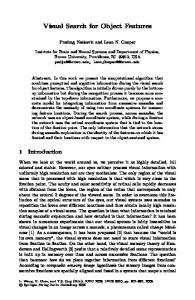
Fig. 1. The 3-dimensional model of the environment
for each image a subset of colored points
o
centre coincident with the synthetic camera position
o
axis direction coincident with the optical axis of synthetic camera;
o
radius R;
o
amplitude defined by an angle (� 90°) that is half the cone angle measured from direction axis;
for each selected colored point, a distance d i respect the location of generated solid image is calculated:
di �
� X i � X 0 �2 � �Yi � Y0 �2 � �Z i � Z 0 �2
(1)
�
local descriptors extracted from the two images; as a result of global descriptor preliminary screening, a number of potentially similar images are than selected out of the database;
each selected RGB point is projected on the solid image defining its image coordinates by means of IO/EO parameters inside the collinearity equations:
r � X � X 0 � � r21 �Y �Y 0 � � r31 �Z � Z 0 � � � � 0 � c 11 r13 � X � X 0 � � r23 �Y �Y 0 � � r33 �Z � Z 0 �
r � X � X 0 � � r22 �Y �Y 0 � � r32 �Z � Z 0 � � � � 0 � c 12 r13 � X � X 0 � � r23 �Y �Y 0 � � r33 �Z � Z 0 � where
�r
11
�
for the selected images, the pairwise matching procedure with query image is executed between the extracted key points, trying to couple similar key points present in both images that may represent two view of the same point. For each feature descriptor of the query image, one and only one similar feature descriptor is searched
�
the matched key points are validated by a geometry check (see section 3) based on the concept that the statistical properties of the log distance ratio for pairs of incorrect matches are distinctly different from the properties of that for correct matches.
(2)
, r12 , r13 , r21 , r22 , r2 ,3 , r31 , r32 , r3, 3 � are the
coefficients of a 3x3 spatial rotation matrix R� ,� , K depending from the camera attitude �� , � , K �
cos� cos� � � R ω�κ � � cos �sen� � sen�sen� cos � � sen�sen� � cos�sen� cos � �
�
� cos�sen� cos� cos� � sen�sen�sen� sen� cos� � cos �sen�sen�
sen� � � � sen� cos� � cos� cos� �� (3)
the image coordinates �� i ,� i � is converted in pixel coordinates �ci , ri � using:
n � ci � i � col d pix 2 �i nrow ri � � � d pox 2
(4)
�
the RGB values of each point are written inside the cell of image RGB matrices in the position �ci , ri � ;
�
the distance value d i is written inside the cell of range
�
at the end of the procedure, pixels still void are filled by means of an interpolation algorithm based on nearest filled pixels.
image matrix in the position �ci , ri � ;
C. The retrieval of reference image out of the reference database The goal of the retrieval procedure is to select a reference image out of the images database with the highest level of similarity with the image acquired by the terminal camera, target of positioning procedure. To select out of a database the most similar image, the following operations have been defined by MPEG CDVS: �
Local descriptors in query and database images are extracted and compressed
�
the images of the database are preliminary ranked based on global descriptors [10] similarity score with the query image. Global descriptors provide a statistical representation of a set of most significant
Based on a statistical model, a set of good reference images can be ranked by a similarity score given by: �
the correct pairwise key points selected by DISTRAT (section III) check;
�
the reliability of each selected match, given by the distance ratio between the first and the second closest descriptors detected in the reference image.
Due to the potential large number of images in the database, MPEG CDVS uses a light representation [3] of descriptors to speed up the retrieval process. Furthermore only a limited number of keypoints are considered for the image search procedure, based on its empirical statistical relevance; in particular, priority is given in current CDVS, among other parameters, to key points located closer to the center of the image. This maximize the probability of finding an object using a compact representation of the visual information. For IRB positioning applications, a homogeneous distribution of key points in the overall query picture is required to optimize the visual search procedure without a selection of the key-points based on the position in the image. This is due to the fact that in some common view, for both outdoor and indoor conditions, the image center represents the infinite point of the perspective view of the image, the key points in the center are therefore far from the camera while points in the edge may be closer to the camera. If selected key points are mainly in the center of the query image (as in current CDVS solution), in some common image view, the geometric distribution of key points may result poor because the 3D points are all far from the camera and concentrated in a limited region, this causes a loss of accuracy in camera position estimation (sect. II.D). D. Camera parameters estimation procedure The second step of the location procedure, EO parameters estimation (position and orientation) is based on the resolution of collinearity equations where key points of the query image are associated with 3D position information available in the reference image extracted out of the database, with related spatial information (see II.B). The 3D information is stored in solid image approach [11] where for each pixel the distance (range) of the obstacle depicted in the image is reported,
the DB, derived from the three-dimensional model of the scene [ 11,13] see [appendix 1];
together with IO/EO parameters of SI in terms of orientation, focal length, sensor position. The information that should be estimated in the location procedure are the EO parameters (position and orientation) of the query image camera, the IO parameters (focal length, and principal point coordinates) are as well estimated in the procedure on order to improve the accuracy of EO parameters estimation. The procedure to estimate EO/IO parameters of the query image camera from a solid image, as defined in [8], consists of the following steps: 1. extracting features from query and reference images using SIFT detector [12] or CDVS key point detector [3], see also fig. 13;
6. the Direct Linear Transformation (DLT) is estimated processing information related to common key point in the images pair, using pixel coordinates of query image and related 3D points obtained in the previous step [14], with this procedure camera parameters (position, orientation, focal length and sensor position) are roughly estimated; the 11 DLT parameters, that are a mathematical combination of physical parameters, combined to linearize the collinearity equations system are decoded to obtain the EO/IO parameters in a first approximation [14];
2. key points matching procedure where only query image key points that have one and only one similar descriptor among key points in reference image are selected, according to an approach slightly modified with respect to the one proposed in [12]. The evaluation of features similarity for matching procedure may be done using an Hamming distance approach where the descriptor array is encoded as a list of three levels binary values [3];
7. the rejection of outliers not detected by step 3 and 4 is executed with a data snooping process [15]: for given 11 DLT estimates, the post fit residuals are calculated in terms of the distance between the projection of the solid point on the estimated query image plane and query image key point coordinates, if the largest residual exceeds a threshold the point with highest residual is discarded and the DLT parameters are estimated again;
3. a geometric check (DISTRAT) described in section 3 is used for a coarse preliminary rejection of matched outliers, the use of DISTRAT is required to speed up outliers rejection procedure However, the DISTRAT output still contains few percentiles of outliers in the selected set of paired features.
8. using the collinearity equations the EO parameters are refined ([7],[16],[17]), this step requires to know the focal length out of a calibration process;
4. given the set of common features selected out of DISTRAT geometric check, the fundamental matrix is estimated with a RANSAC procedure, where the fundamental matrix is a representation of the rototraslation of the camera between query image and reference image [6]; this step allows to exclude remaining outliers out of DISTRAT check; RANSAC is a robust iterative method to estimate parameters of a mathematical model (the fundamental matrix in this case) from a set of observed data which contains outliers. The RANSAC processing load depends on the percentage of good matches (inliers), for lower rate of inliers the processing load increases dramatically. The preliminary use of DISTRAT reduces the percentage of outliers from 70% order to few percentiles, this allows to strongly reduce the RANSAC execution time, approximately of 100 times (at this stage focal length is assumed to be similar in both images out of retrieval step and the camera distortion model [7] are not taking into account); 5. The spatial information (3D coordinates) of the common features between query and reference image is retrieved using the solid image information available for the reference images of
9. the reliability of the final estimated location can be validated using the variance covariance matrix of the collinearity equation [17] and checking again the post fit residuals. III.
DISTRAT GEOMETRIC CHECK FOR FAST OUTLIER REJECTION
In image recognition technology based on local descriptor analysis, several interest points are found for each of two images. These are then matched in pairs such that each probably represents two views of the same point on depicted objects. These matches are not always correct, as only the properties of neighborhoods around the interest points are taken into account. After the matching it is therefore necessary to carry out one or more of the following steps of the geometric verification problem: � determine if any of the point matches are correct; � determine how many of the point matches are correct; � determine which of the point matches are correct. Many solutions have been proposed for the geometric verification problem. Most methods explicitly compute image transformations and build on RANSAC [20] speeding it up by introducing new search strategies. Examples are PROSAC [21], SCRAMSAC [22], and BETASAC [23]. Other methods, often called weak consistency methods, trade some accuracy for speed by using fast rules for spatial consistency instead of computing transformations.
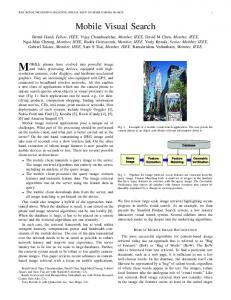
Examples are the techniques of Sivic and Zisserman [24] Jegou [25], and Calonder et al.[26], all designed for visual search. To speed up the outliers rejection process, we use DISTRAT, a fast method that was originally adopted for visual search, adopted by MPEG CDVS as part of the test model for comparing image pairs [27]. DISTRAT achieves approximately the same accuracy as RANSAC-based methods, while also being very fast. In addition, it works well when there are relatively few correct matches. The method evalutes a histogram of the logarithmic distance ratio (LDR for short). The statistics of the LDR depend on whether the matches are correct (inliers) or incorrect (outliers). The density for outliers is rather broad, for inliers it is narrow. For image pairs that do not depict objects in common (called nonmatching pairs), all matches are outliers and the LDR histogram will resemble the outlier density (see fig. 2).
Fig. 2. The LDR histogram in case the pair of image depictes different scenes
For image pairs that do share depicted scene (matching pairs), the histogram component due to inliers will be relatively narrow while the component due to outliers will resemble the outlier density (see fig. 3).
IV.
INDOOR AND OUTDOOR TEST SITES
In order to verify the effectiveness of the proposed procedure (section II), two different survey campaign were carried out, in two different environment. For indoor test site, the WinLab (a Lab for demos) at the Telecom Italia premises in Torino, made of 5 rooms, have been mapped with a TLS. In outdoor, the survey has been carried out in an area over three blocks in via Garibaldi, an historical central pedestrian road, in Torino. Both surveys were executed with a Faro laser scanner (series Cam2 Focus 3D). The 3D model of the environment in terms of a cloud of coloured 3D point can alternatively be acquired using Mobile Mapping Systems (MMS), that allo to get information over a large area in a short time [18] [19]. A. Indoor test site Fig. 4 depicts in detail the lab where the location algorithm has been tested. Seven scans (fig. 4, red points) have been executed to build an extensive 3D model (fig. 5 and 6). The 3D model is used to build the solid images database as described in chapter 2.B. In figure 7 it is presented a sample of synthetic images part of the reference images database of the WinLab. As the indoor trial has been a very preliminary test, the projection points used to build the synthetic images database, were assumed coincident with the scan positions. This assumption in the selection of projection point used to build the database, causes slight degradation accuracy performances of positioning procedure with respect to a more complete set of projection points, as described in section V.
Fig. 3. The LDR histogram in case the pair of image depictes the same scenes. This LDR histogram is referred to the pair of images illustarted in fig. 16 a.
The DISTRAT method takes advantage of the different aspects of inlier and outlier pdfs in two ways, one for each of its two steps. In the first step, a goodness-of-fit test is used to check whether the LDR histogram is different enough to reject the hypothesis that two images have no objects in common. In the second step, the LDR histogram (as a vector) is projected onto the discretized outlier histogram, and the projection error is used to construct a matrix whose expected value has the exact arrangement of inliers as its dominant eigenvector.
Fig. 4. Map of Telecom Italia WInLab.
Fig. 5. The spherical image generated with the scan 3 Fig. 8. Outdoor laserscan positions.
Fig. 6. The spherical image generated with the scan 5
Fig. 9. Examples of outdoor spherical images
Fig. 7. Example of synthetic images part of the database for indoor site.
B. Outdoor test site In outdoor test site six scans have been acquired (fig 8) over a 3 blocks area in a historical pedestrian road for a length of about 150 m. Examples of scans used to generate the DB of reference images are presented in fig. 9. In order to generate a reference images database characterized by an exhaustive coverage of all the possible perspective of the environment, a grid of points have been taken into account, points are spaced 2 meters on the direction orthogonal to buildings front and 3 meter on the direction parallel to building front. For each points 16 different headings on the horizontal plane and 4 different inclination of the vertical axe (0, 5, 10 and 15 degrees) have been considered. In figure 10 an example of outdoor synthetic images of the DB is reported.
Fig. 10. Example of synthetic images part of the database for outdoor site. For a selected point 2 consecutive headings (out of 16) in horizontal plane (one per line) with 0, 5 and 10 degrees inclination on vertical plane.
C. Groundtruth position estimation and camera calibration In order to estimate the accuracy of IRB positioning procedure, for each test site (indoor and outdoor) 15 images have been accurately geo-located using:
�
an ad hoc system (named “butterfly”) consists on a car support for mobile phone mounted on a plate with 4 colored spheres (red, blu, yellow and grey); high precision topographical survey of “butterfly” spheres.
12,00 10,00
Dr [micron]
�
Dr
8,00
Dr resi dual
6,00
Trend
4,00 2,00 0,00 2,00
0
0,5
1
1,5
2
2,5
3
y = 3,4824x
4,00
2
R = 0,8118 6,00 r [mm]
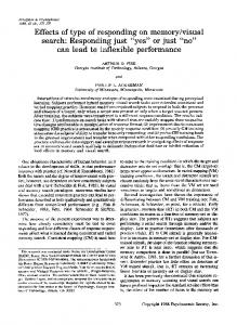
Fig. 12. Radial distortion shape of the smartphone camera. In red the values after the correction of the linear trend
In case a calibration procedure cannot be easily executed prior to running the application, the focal length estimation can be obtained by processing an image of the area where the 3D survey is available that should be characterized by key-points laying over multiple planes, perpendicular each other’s or parallel as well. The focal length is estimated solving the DLT equation. V. Fig. 11. The butterfly system durng query images acquisition in indoor case
The images were acquired using a Samsung smartphone (Galaxy S Advance) that was previously self-calibrated, using a dedicated calibration field outside the Geomatics Laboratory of the Politecnico di Torino, in order to know the internal orientation parameters (principal distance and coordinates of the principal point). In this calibration procedure, distortion parameters of the smartphone camera have been also estimated and they are shown in the figure 11: the blue shape represents the obtained radial distortion that was corrected of the linear trend getting the magenta shape. This operation is equal to carry a scale factor changing the principal distance value previously estimated in the calibration process. We notice that for the accuracy required by main use case as pedestrian navigation or augmented reality, equal to few decimetre order, radial distortion parameters are negligible and we do not take those correction into account. When the point view of query image lay on one single plane the DLT operation cannot estimate accurately the principal distance of the camera. For the success of proposed EO parameters estimation procedure, IO camera parameters must be previously estimated by a calibration process; in particular a prior focal length estimation is required due to the misalignment with respect to nominal values available in the parameters of the image jpeg file generated by the mobile phone.
TRIAL RESULTS
In order to test the effectiveness of proposed location procedure, we have evaluated the processing load benefit and the accuracy of the approach. For accuracy estimation we have considered a set of smart phone images geo-located, in terms of position and attitude, as described in Section IV C. A. Processing load The tests, in both scenarios indoor and outdoor, have shown that the use of DISTRAT geometric check in pairwise matches outliers rejection allows to reduce processing time of a factor of 10 times or more with respect of pure RANSAC procedure, in case of medium degree of similarity between the query and the reference image, guaranteeing at the meantime an good level of accuracy. Tab. 1 describes the processing load results of outlier rejection procedure for pure RANSAC procedure versus the hybrid DISTRAT and RANSAC approach, for an an Intel Core 2 T7500 processor. In case the similarity between query and reference image is not so high (the rate of good matches is around 30%) (fig 15) the hybrid approach provide strong benefit. In case the image show good similarity (fig. 16) the processing load for the 2 approaches are similar. Rate of inliers 35% 70%
RANSAC only 10 sec 0.5 sec
DISTART+RANSAC 0.6 sec 0.6 sec
Tab. 1 Processing load gain: hybrid DISTRAT and RANSAC vs RANSAC
If fast matching procedure based on trinarized descriptors and Hamming distance is adopted, the rate of inliers among
matched pairs is lower and the benefit of the hybrid DISTRAT and RANSAC rejection outlier approach is more important. B. Indoor accuracy The figure 13 below describes two example of position estimation procedure for given query images and the correspondent selected reference images (see Section II.C), with representation of good pairwise matched key points (green) and matching outliers (red).
be avoided. In case of all query images key points laying in a single plane (figure 14) to correctly estimate camera parameters it is necessary to know the focal length of the camera through a previous calibration process or through a location procedure with a query image with key points laying on multiple planes (see fig 13).
Fig. 14. Examples of query image with a key pints laying in a plane parallel to sensor plane.
Fig. 13. Examples of query and reference (out of the database) images key points matching results for indoor results.
The figure 15 represents a scenario where the query image has picked in remarkably different conditions with respect to the TLS conditions, a sufficient number of key points have been detected and camera position and orientation can be calculate anyway. We observed that in camera parameter estimation procedure (see II.D) a larger numebr of key points should be considered in the query image to process not ideal images (c.a. 2000), a lower number of key points can be considered in the reference image (i.e.1200) acquired in more stable conditions. In the selection process, key points have been ranked based on the peak, nevertheless taking into account other parameter like scale could bring benefit in terms of reduction of numeber of key points considered in the procedure.
The table below summarizes the accuracy results in terms of discrepancies from ground truth and estimated values, for indoor trial in case of good level of similarity between the query image and the reference one extracted out of the database. param. |Max| Mean Dev. St.
�X [m] 0.164 0.018 0.084
�Y [m] 0.149 0.010 0.086
�Z [m] 0.063 0.015 0.020
�ω [rad] 0.4646 0.0975 0.1850
�φ [rad] 0.5288 0.0544 0.1689
�k [rad] 0.2396 0.0573 0.1022
Tab. 2 Accuracy results in indoor trial for position (�X �Y �Z) and attitude (�ω � φ �k)
With good reference image similarity, the 3D positions have maximum discrepancies in absolute values of 16 cm along Xaxis, 18 cm along Y-axis, 6 cm along Z-axis; the standard deviations are about 8 cm in horizontal plane and 2 cm in height (Z). The maximum orientation error is about 0.5 rad. We can summarized that the standard deviations of 3D position are about 10 cm and while 0.15 rad for the attitude and there are no systematic errors in either position and attitude estimation Note that in both figure 13 images, the key points lay on more than one plane, in this condition the calibration procedure could
Fig. 15. Examples of query image shot in real condition paired with selected database image.
C. Outdoor accuracy The figure 16 describes two examples of results of reference images selection procedure (see section II.C), with representation of good pairwise matched key points (green) and matching outliers (red). Query images and TLS are acquired in not ideal condition including people and cars randomly present in the scene. A maximum number of 2000 key points have been selected, ranked by the absolute value in descending order of the response of the keypoint to the Laplacian of Guassian filtering (peak), in both query and reference image, this large number is used to avoid problems due to partial obstruction of scenes. As in indoor scenario, weighting the key points based on the scale would bring benefit in terms of reduction of number of key points.
REFERENCES [1]
[2]
[3] [4] [5] [6]
[7] [8]
Fig. 16. a,b Examples of query and reference (out of the database) images key points matching results for outdoor scenario (green good matches, red outliers).
The table below summarizes the accuracy results in terms of discrepancies from ground truth and estimated values for outdoor trial in case of good level of similarity between the query image and the reference one extracted out of the database. �ω [rad] 0.139 0.035 0.098
�φ [rad] 0.037 -0.012 0.047
[12]
Tab. 3 Accuracy results in outdoor trial for position (�X � Y �Z) and attitude (�ω � φ �k)
[15]
The standard deviations of discrepancies are about 30 cm in position and about 0.15 radians in attitude. No systematic errors are present.
[16]
In many case the focal length is required to get good parameter estimation, in particular in all the case where we have the key points laying on a single plane.
[18]
VI.
�Z [m] 0.320 0.045 0.191
[11]
[13]
|Max| Mean Dev. St.
�Y [m] 0.500 -0.023 0.383
[10]
�k [rad] 0.118 -0.081 0.093
param.
�X [m] 0.420 0.059 0.249
[9]
[14]
[17]
[19]
CONCLUSIONS
In this paper, we have analyzed the performances in terms of accuracy of position and orientation of an original procedure of image recognition based positioning using TLS and exploiting the MPEGC DVS standard. In particular we have shown that the use of DISTRAT geometric check may reduce, in real working conditions, the processing time of a factor 10, due a fast coarse mechanism for discarding pairwise matches outliers. The proposed location procedure offer good level of accuracy with a standard deviation of few decimeters in indoor/outdoor scenarios.
[20]
[21]
[22]
Cina A., Piras. M., “Indoor positioning using low cost GPS receivers: Tests and statistical analyses”. In: the 2010 International Conference on Indoor Positioning and Indoor Navigation (IPIN), Zurigo (CH), 1517/09/2010. pp. 537-543 R.Mautz and S.Tilch, “Survey of Optical Indoor Positioning Systems", International Conference on Indoor Positioning and Indoor Navigation (IPIN), 21-23 September 2011. CDVS (2014). ISO/IEC DIS 15938-13 Compact Descriptors for Visual Search PCT/EP2011/050994 “Method and system for comparing images” PCT/EP2012/050025 “Method and system for comparing images” Multiple View Geometry in Computer Vision Second Edition. Richard Hartley and Andrew Zisserman, Cambridge University Press, March 2004. Editor in Chief C. Mc Glone Manual of Photogrammetry 5th edition ASPRS, p 280-281 Piras M., Dabove P., Lingua A.M., Aicardi I., “Indoor Navigation Using Smartphone Technology: A Future Challenge Or An Actual Possibility?” ION PLANS 2014 May 5-8, 2014 Monterey, USA Carosio A.; Cina A.; Piras M. “The Robust Statistics method applied in the Kalman filter: theory and application”. In: ION GNSS 2005, Long Beach, CA (USA), SEPT.13-16, 2005. pp. 525-535 Visual Standard for Content Description—An Overview, Sikora, IEEE TRANSACTIONS ON CIRCUITS AND SYSTEMS FOR VIDEO TECHNOLOGY, VOL. 11, NO. 6, Bornaz L., Dequal S. (2003) - A new concept: the solid image. CIPA 2003 Proceedings of XIXth International Symposium: 169-174. Lowe D., 2004. Distinctive image features from scale-invariant keypoints. International, Journal of Computer Vision 60(2): 91-110 G. M. Forno, A. M. Lingua, S. Lo Russo, G. Taddia, M. Piras (2013) “GSTOP: a new tool for 3D geomorphological survey and mapping”, European Journal of Remote Sensing - 2013, 46: 234-249, doi: 10.5721/EuJRS20134613, p. 239-242 Editor in Chief H.M. Karara, Non Topography Photogrammetry Second Edition ASPRS pp46-48 W. Baarda, (1968). A testing procedure for use in geodetic networks, Publications on Geodesy 9 (Vol. 2 Nr. 5), Delft, 1968. 97 pagina's.I SBN-13: 978 90 6132 209 2. ISBN-10: 90 6132 209 X, pag. 53-55 K. Kraus Photogrammetry: Geometry from Images and Laser Scans, Volume 1, pag 21-29 K. Kraus Photogrammetry: Geometry from Images and Laser Scans, Volume 1, pag 184-189 De Agostino M., Lingua A., Marenchino D., Nex F., Piras M., “GIMPHI: a new integration approach for early impact assessment”. In: APPLIED GEOMATICS, vol. 3 n. 4, pp. 241-249. - ISSN 1866-9298 Dabove P., De Agostino M., Manzino A.M., “Mass-market L1 GPS receivers for mobile mapping applications: a novel approach”. In: 24nd International Technical Meeting of the Satellite Division of the Institute of Navigation 2011 (ION GNSS 2011), Portland (OR - U.S.A.), 20-23 Settembre 2011. pp. 1068-1074 M. A. Fischler and R. C. Bolles, “Random sample consensus: a paradigm for model fitting with applications to image analysis and automated cartography,” Communications of the ACM,vol. 24, pp. 381– 395, June 1981. O. Chum and J. Matas, “Matching with PROSAC – progressive sample consensus,” in Proceedings IEEE Computer Society Conference on Computer Vision and Pattern Recognition (CVPR), vol. 1, pp. 220–226, IEEE Computer Society, 2005. T. Sattler, B. Leibe, and L. Kobbelt, “SCRAMSAC: Improving RANSAC’s efficiency with a spatial consistency filter,” in Proceedings of the IEEE International Conference on Computer Vision, 2009, pp. 2090 – 2097, 2009.
[23] A. Meler, M. Decrouez, and J. Crowley, “BetaSAC: a new conditional sampling for RANSAC,” in British Machine Vision Conference, 2010. [24] J. Sivic and A. Zisserman, “Video Google: A text retrieval approach to object matching in videos,” in Proceedings Ninth International Conference on Computer Vision, pp. 1470–1477, IEEE, 2003. [25] H. Jegou, M. Douze, and C. Schmid, “Hamming embedding and weak geometric consistency for large scale image search,” in Computer Vision–ECCV, pp. 304–317, Springer, 2008. [26] M. Calonder, V. Lepetit, and P. Fua, “Keypoint signatures for fast learning and recognition,” in Computer Vision–ECCV 2008, pp. 58–71, Springer, 2008. [27] S. Paschalakis, G. Francini, G. Cordara, M. Bober, L. Duan, K. Iwamoto, and V. Chandrasekhar, “Test Model 10: Compact Descriptors for Visual Search,” Tech. Rep. N14393, ISO/IEC JTC1/SC29/WG11 (MPEG), Valencia, Spain, Apr 2014. [28] S. Lepsoy, G. Francini, G. Cordara, and P. P. de Gusmao, “Statistical modelling of outliers for fast visual search,” in IEEE International Conference on Multimedia and Expo (ICME), pp. 1–6,IEEE, 2011
APPENDIX 1 THE USE OF SOLID IMAGES FOR ESTIMATION OF 3D
d � D�c I , rI � �
n � � � I � � cI � c � � � pix 2� � n � � � I � � � rI � r � � � pix 2� � �
�X
each
solid
Cp , YCp , Z Cp �
image
information
about
position
, orientation �� , � , K � , and sensor resolution
� pix
should be available. Therefore for each solid image considered, it is possible to define the rotation matrix: cos� cos� � � R ω�κ � � cos �sen� � sen�sen� cos � � sen�sen� � cos�sen� cos � �
� cos�sen� cos� cos� � sen�sen�sen� sen� cos� � cos �sen�sen�
sen� � � � sen� cos� � cos� cos� ��
In order to estimate the spatial position of the object detected in the RGB image the following procedure should be applied [11]: � Extraction of distance from range matrix see section 2.B:
Calculus of spherical angular coordinates:
��
�i
c � � I2 � � � arctan I c
�
POSITION OF KEY POINT
For
Definition of image coordinates related to each single feature:
2
Definition of object coordinates respect to image system :
� x0 � d cos � sin � � y0 � d sin � � � � z � �d cos � cos � � 0 �
Roto-translation into object coordinate system:
� x0 � � X 0 � � X Pc � � � � � � � � Y0 � � � YPc � � R�� ,� , K � � y0 � �z � �Z � �Z � � 0� � 0 � � Pc �
��������������������������������������������������������������������������� ��������������������������������������������������������������������������������� �����������������������������������������������������