class 10000 clean rooms for the laser. It will deliver the beam to four experimental areas. The pumping energy for the main amplifier is stored in a large capacitor ...
Proceedings of ICALEPCS2003, Gyeongju, Korea
THE PHELIX CONTROL SYSTEM BASED ON UML DESIGN LEVEL PROGRAMMING IN LABVIEW H. Brand*, D. Beck, E. Gaul, W. Geithner, S. Götte, T.Kühl, K. Poppensieker, M. Roth, U.Thiemer, GSI, DVEE, Planckstr. 1, D-64291 Darmstadt, Germany Abstract
Z6
fs-frontend Diagnostics
Preamp ns-frontend
XRL cmpressor
The Unified Modeling Language (UML) [1] has become the standard for documentation and high level design of modern software. UML to code generators like Rational Rose, Together, Rhapsody etc., allow to convert the UML diagrams to text based languages like C++ or Java and vice versa. Instead of converting the UML graphs to another programming language prior to its use, it is much better if the UML diagram itself is already executable. This is made possible by the third party toolkit ObjectVIEW [2] which can be used within the graphical language LabVIEW [3]. As an example of this approach the application layer of the control system of the PHELIX, Petawatt High Energy Laser for heavy Ion eXperiments [4], facility at GSI is presented.
SF6
Amp1 Amp2 Amp3 Amp4 Amp5
Main amplifer Booster amplifier
Diagnostics
Amp6 Amp7 Amp8 Amp9Amp10
ESR HHT
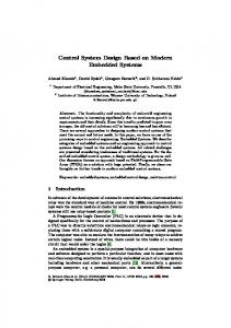
INTRODUCTION The combination of a high power laser and a heavy ion beam is unique and opens new fields for research in plasma physics, fusion, atomic spectroscopy etc. The laser is set up in a two story building, 20 m x 23 m, with class 10000 clean rooms for the laser. It will deliver the beam to four experimental areas. The pumping energy for the main amplifier is stored in a large capacitor bank at 20 kV. For safety reasons and convenience all devices must be controlled remotely. Figure 1 shows a schematic view. In many cases, the graphical programming language LabVIEW has become the default development environment because of its fast learning curve and easy access to typical hardware equipment. Therefore it has been decided to develop the Control System (CS) framework [4] which is tuned for performance especially in the device layer. A dedicated control system can easily be set up by adding experiment specific add-ons to the framework. In case of PHELIX the application layer will be implemented by using ObjectVIEW's implementation of Object- and Petri-Nets with respect to UML 2.0, so the code can be it's own documentation which is convenient when considering the long term maintenance of that facility.
REQUIREMENTS PHELIX is built up from several subsystems as there are femto- and nanosecond frontends, pre-, main- and booster-amplifiers as well as some diagnostic stations. There are a lot of different devices that have to be controlled remotely: Laser diagnostics - ~30 digital cameras for the spatial and spectral beam profile
472
Figure 1: Schematic view of the PHELIX setup. The high voltage capacitor bank is located in the upper floor. The beamlines to the experiments are only denoted. - ~10 oscilloscopes to measure the temporal beam profile with fast diodes - 10 power meter to measure the pulse energy. Laser alignment - ~100 axis for control of the laser beam alignment with mirrors and lenses - ~90 digital IO to control about 30 crosshairs which define the optical axis High Voltage System - 12 high voltage power supplies, ignitrons and dump circuits are controlled by - ~100 digital outputs and ~10 DACs ~260 digital inputs and 50 slow ADCs and ~120 fast ADCs, 10 kHz, to measure the discharging currents Safety System - ~150 digital IOs, ~50 safety relays and ~40 safety relay combinations to provide safety - CerPass [6] is used for access control Timing system - Gate and delay generators have to be configured for the relative timing of all instruments in the sub nanosecond regime. - An external trigger determines the relative timing with the ion beam from the accelerator Although PHELIX has a static setup the installation and commissioning phases require a highly flexible control system, where operational states can be configured on the fly. Once the commissioning has finished the control system has to assist the operator for
Proceedings of ICALEPCS2003, Gyeongju, Korea
efficient operation. Therefore SCADA functionalities like alarming, trending and user management are necessary. The control system has to do more than just setting some parameters and to acquire data. Sequences have to be repeated periodically, with a rate exceeding 10Hz. Moreover, the different steps in such a sequence need to be synchronized with a precision of about 100ns, in case of PHELIX even in the sub-nanosecond range. Alignment procedures and the countdown for a laser shot are typical sequences. Furthermore finite state machines with well defined transitions have to be implemented and maintained, e.g. for the safety and access control. Important is the ability to call any function of any device at any moment. Then, observables can be measured as a function of any parameter of the experiment. This feature allows investigating systematic effects and debugging of an apparatus even for those parameters which are not used in the preconfigured operational modes. The controlled devices are distributed and connected to different PCs or via gateways to Ethernet. In some cases safety requires that the users must not be close to the experiment. This implies a distributed system with remote access.
SOLUTION Most hardware devices stem from third party manufacturers and can be integrated via interfaces like RS232, RS485, GPIB, Firewire, CAN-Bus to the device layer provided by the CS framework which also implements the network connectivity. SCADA functionality like trending, alarming and user management is provided by the Datalogging & Supervisory Control (DSC) module of LabVIEW as well as OPC connectivity to enable access to, e.g. hardware connected via Profibus. The application layer can be implemented by using the Object- and Petri-Net provided by ObjectVIEW.
Hardware selection We are using several models of Tektronix oscilloscopes, Stanford Research, SRDG535 and Berkley Nucleonics, BNC555, Gate and Delay Generators with GPIB interface. Coherent power meters, Edwards Active Gauge Controllers and Trinamics 6-axis motion controllers are connected via RS232 and RS485. Basler A302fs digital cameras are connected via Firewire to a PC by using the DCAM standard. Beckhoff bus terminals have been selected to integrate distributed slow control digital and analog IO. They are connected via LWL network and a Siemens Profibus master CP5613 FO. A LabVIEW RT System with PXI 8156 and two PXI-6071 MIO cards is used to measure the discharge currents. All PCs and most instruments with GPIB or serial line interface are connected to a switched Ethernet (100 Mbit/LWL) by using GPIB-ENET, National Instruments, and RS232/RS485-COM-Server, Wiesemann & Theis, as gateways. 473
Object oriented approach, multi-threading and events Today, the CS framework is based on LabVIEW only. ObjectVIEW is a third party toolkit which enables object oriented programming with pure LabVIEW, based on Virtual Instrument (VI)-templates and VI-Server methods. LabVIEW intrinsic functionality - multithreading, reentrancy, LV notifier, LV queues and DataSocket - is used to implement active objects which can react on events. ObjectVIEW is not required for the CS framework.
Object- and Petri-Nets These event mechanisms are also used to implement ports with respect to UML 2.0. The connector pane of a Launch-VI is used to specify the URLs for the ports. The events are exchanged directly between the connected objects. Special VIs are provided to read from and write to a port. ObjectVIEW provides base classes for elementary and hierarchical net objects (EON and HON) as well as Petri-Net objects (PN). A Petri-Net consists of places, edges and transitions. A place can have n markers. A transition switches when the switch condition is true, all connected places have the number of markers or space available that are defined by the weight of the edges. This means that it removes markers from input places and creates new ones at the output places. Petri-Nets can exist in three variants: Condition/Event-Net (C/E) is a specialization of the Place/Transition-Net (P/T) described before with one or zero marker. Predicate/Transition-Nets (Pr/T) have colored markers.
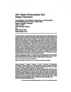
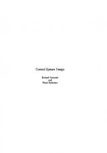
THE PHELIX CONTROL SYSTEM Each subsystem has it's own PC providing the device layer of the CS framework and for local operation with high performance for laser diagnostics, tuning and image processing, as well as live display of the laser beam. In principle all other equipment could be accessed via Ethernet from all PCs. The PCs for remote operation are located in the main control room. The most important goal of the PHELIX control system is the safety and access control as well as the high voltage system. Therefore one PC will host the DSC engine and the Profibus master to avoid unnecessary network traffic. The subsystems will be modelled with Object- and PetriNets as shown in figure 2 and 3 for the safety system. The safety is implemented in hardware. The well defined transitions of the Petri-Net help to enhance the safety. It is also used to activate and deactivate alarms, to assist the search procedure, and to execute the countdown sequence. The Object-Net for the HV system ensures the consistent operation of a collection of power supplies etc. In the same way all subsystems of PHELIX will be modelled with hierarchical object nets (HON). To include user management and lock mechanisms in the application layer elementary net objects (EON) will be used as proxies to encapsulate the simple device layer objects.
Proceedings of ICALEPCS2003, Gyeongju, Korea
CONCLUSION The PHELIX control system will use about 500 active objects which are distributed over about ten PCs with some 10000 process variables. The application of UML design methods within LabVIEW is feasible and makes development as well as maintenance much easier and comfortable. In particular the UML system design is documentation, code and executable!
REFERENCES [1] http://www.omg.org [2] R. Buhrke, LabVIEW Technical Resource, Vol.9, 3. [3] R. Jamal, H. Pichlik: LabVIEW Applications and Solutions, Prentice Hall, 1999. [4] E.W. Gaul et al., GSI Scientific Report 2002 (2003) 101-103. [5] http://labview.gsi.de/CS/cs.htm. [6] http://www.cerberus.com/sec/d/sec_zut.asp
Figure 2: Hierarchical Petri-Net Object for the safety and access control containing four sub-Petri-Nets and the Port Event handler.
Figure 3: Hierarchical Petri-Net Object containing the Petri-Net for the specific state: HV-Operation
474