An informal requirement on the VendingMachine could be stated as follows: âWhenever a customer wants to buy a water drink (thus, inserts at least one 50 cent.
The Rhapsody UML Verification Environment Ingo Schinz, Tobe Toben, Christian Mrugalla, Bernd Westphal Carl von Ossietzky Universit¨at Oldenburg, D-26111 Oldenburg, Germany {Toben,Westphal}@Informatik.Uni-Oldenburg.DE OFFIS, Escherweg 2, D-26121 Oldenburg, Germany {Mrugalla,Schinz}@OFFIS.DE Abstract Object-oriented modeling plays an increasing role in the design of embedded controllers. Formal verification can be applied in order to give evidence for meeting safety critical requirements. The “Rhapsody UML Verification Environment” supports verification of safety and liveness requirements for embedded controllers, developed within the Unified Modeling Language (UML). The verification environment is integrated in the design tool “Rhapsody in C++” offered by the company I-Logix. This paper discusses how UML models are transformed into a format usable for the VIS model checker, shows the specification and verification on a simple example and explains how the tool can be used to help determining the memory resources of a model.
1. Introduction In recent years object-oriented techniques, as well as model based development processes, have become increasingly important for the design of embedded systems. As a widely accepted standard, the Unified Modeling Language (UML) has been established as a formalism for object-oriented system design. The application of high-level abstract specification formalisms as offered by UML can itself be seen as an improvement in the development of embedded systems. Graphical formalisms, like class diagrams or statecharts, increase intuitiveness of the design concept, and simulation capabilities support the validation of the system under development. In this context objectoriented techniques help to formalize properties of the system and its parts as well as to specify relations between its building ingredients. Although object-oriented techniques can help to avoid many conceptual problems and certain design
flaws, correctness of the design with respect to functional requirements can not be guaranteed by construction. Especially in the development of safety or mission critical embedded systems, the application of formal methods can massively improve the quality of the design. Formal verification can be applied in order to give evidence for meeting functional requirements. Besides the ordinary problems as e.g. complexity of the model, a verification environment for UML designs has to cope with object-oriented techniques, such as inheritance, dynamic association of objects, and creation/destruction of objects. In this paper we report on a verification environment for UML models which has been developed in the context of the European research project OMEGA1 . The tool set has been integrated within “Rhapsody in C++” [7], a commercial design tool offered by the company I-Logix, and is based on the VIS (Verification Interacting with Synthesis) model checker [8]. Requirements to be verified can be specified using predefined temporal patterns or the graphical specification formalism Life Sequence Charts (LSC) [5]. The LSC language was developed to overcome the shortcomings of Message Sequence Charts and Sequence Diagrams which both lack expressivity and a formal semantics [12]. The supported action language for modeling actions and requirement specifications is a subset of the programming language C++. This subset as well as a concrete semantics of the supported UML-subset has been defined in OMEGA [4]. The interaction of the model with its environment is restricted to event communication. In order to specify the communication interface of the model the user has to define a set of events as being external. These external events are controlled by the model checker as inputs for the model. In order to restrict the possible environment behavior with respect to this event communica1
IST-2001-33522 OMEGA, http://www-omega.imag.fr/
tion, the user of the verification environment can specify assumptions about possible event sequences provided by the environment using the specification techniques listed above. If the model checker detects a dynamic violation of a requirement specification, an errorpath is issued showing a concrete computation of the model violating the requirement.
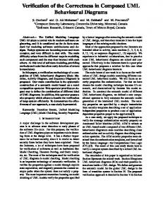
2. Tool Overview For a better understanding of the subsequent sections, we give an overview of the verification environment first. Figure 1 shows an abstract view of some of the tools and file formats and their interaction.
Rhapsody
PatEdit
LSCEdit
XMI
Pattern
LSC
pat2tl
lsc2tl
Transform
SMI
smi2fsm
FSM
CTL VIS
Trace
trc2std
trc2lsc
STD
LSC
Figure 1. Structure of the verification environment. A‘ ’ symbolizes a tool, ‘ ’ a file format, ‘ ’ a flow of data, and the dashed lines seperate the four levels “Input”, “Transformation”, “Model Checking”, and “Output”.
specification have to be transformed into the input formats of the model checker – that is, a finite state machine (FSM) description of the model and a computation tree logic (CTL) formula for the specification. The left axis of figure 1 shows that the UML model, which was designed within “Rhapsody in C++”, is exported as an XMI [19] representation. This format is the starting point for a multitude of transformation steps which finally lead to a representation of the model in the SMI [1] language. SMI (System Modelling Interface) has been developed at our department during recent years and is a simple imperative language for describing symbolic transition systems. SMI is translated into an FSM description in the VIS input syntax. The right axis of figure 1 indicates that a temporal pattern definition as well as an LSC can be translated into an adequate CTL formula. Details of these procedures can be found in [20] and [12]. Both the FSM and the CTL formula are then fed into the VIS model checker, which either will state that the formula is true, or will produce a trace showing a violating run of the system. This output talks about the bit-level representation of the transformed model and is thereby hardly readable for the designer. In order to become comprehensible, the trace is backtranslated into UML terminology so that model-constituents like objects, associations, and event queues become visible again. In some sense, the model transformations which have been performed on the way down to the FSM description have to be reversed for the trace. Our tool presents two aspects of the trace by using two different visual formalisms. On the one hand, a symbolic timing diagram (STD) [22] lists the changes of the objects’ attributes and statechart configurations. On the other hand, the event communication between the objects of the model which led to the contradiction of the specification is displayed as an LSC2 . We want to emphasize that the whole procedure is completely integrated into “Rhapsody in C++”. The user of the verification environment can build the UML model, formalize the requirement, invoke the modeltransformation and -verification, and analyze the trace without having to leave the Rhapsody toolkit. Technically we are using Rhapsody’s capabilities to instantiate Makefile templates in order to call the underlying tool chain. The following sections describe some parts of the verification environment in more detail. In section 3 we will show on a simple model how to perform a 2
To be able to use the VIS model checker to verify requirements on the UML model, both the model and the
here, the LSC is not meant as a specification language, but only serves as a visualization tool for totally ordered message occurrences.
verification task and how to read the counterexample generated by the model checker. Speaking in terms of figure 1, this section will talk about “Rhapsody”, “LSC” as specification language, and the combination of “STD” and “LSC” as errorpath visualization. Section 4 describes how object creation and destruction as well as dynamic addressing is represented for the model checker, and proposes an iterative procedure to determine upper bounds for the memory consumption of the model. The transformation of other object-oriented concepts and UML constructs is sketched in Section 5. These points correspond to the “Transform” part in figure 1.
3. The Verification Procedure We use a small example of a vending machine model to demonstrate the verification procedure.
VendingMachine CoinValidator fallthrough():void update_ChoicePanel( C50() E1() OK() 1 1
DrinkDispenser 1
Prepare_Water():int Prepare_Soft():int Prepare_Tea():int DWATER() DTEA() DSOFT() FILLUP()
1
ChoicePanel Water_enabled : int Soft_enabled : int Tea_enabled : int disable_all():void enable_Water():void enable_Soft():void enable_Tea():void WATER() SOFT() TEA()
nent”: the machine only signals if a particular drink is in stock after the corresponding amount of money is inserted. The machine can hold at most three drinks of each kind, but it can be refilled by the external event ‘FILLUP’. This event then enables those drink lamps for which an adequate amount of money was already inserted into the machine. An informal requirement on the VendingMachine could be stated as follows: “Whenever a customer wants to buy a water drink (thus, inserts at least one 50 cent coin followed by pushing the water button) and the VendingMachine is not out of water drinks, then a water is prepared and dispensed to the customer”. To see how one can use the “Rhapsody UML Verification Environment” to check whether this requirement holds, we first take a look at some parts of our UML model of the VM. After that, we will formalize the requirement and show how to interpret the results of the model checking procedure. The VendingMachine is modeled as a composite class with the four parts CoinValidator, ChoicePanel, DrinkDispenser, and Changer (cf. fig. 2). All rolenames of the depicted association links are constructed by adding the prefix “its” to the target class name, i.e. the CoinValidator knows the ChoicePanel under the name “itsChoicePanel”.
1 C50
giveback_100():void giveback_50():void
Entry Action: itsChoicePanel ->enable_Soft()
Idle
Changer 1
E1
Entry Action: itsChoicePanel ->enable_Tea()
OK
waitOK
E1/fallthrough() have_c100_or_e1>
have_e1
C50/itsChoicePanel ->enable_Water() E1/fallthrough()
have_c50> C50
Figure 2. The class diagram of the VM.
have_c100
C50
have_c150>
E1/itsChoicePanel->enable_Soft()
The VendingMachine (VM) sells drinks. Water at the price of 50 cent, a softdrink at the price of 1 euro, and tea at the price of 1.5 euro. As coins are inserted, lamps on a choice panel signal the possible choice. After pushing one of the enabled buttons, the corresponding drink is prepared and dispensed, and the inserted money is stored in the machine whereby change is given to the customer if required. For reasons of simplicity, the VendingMachine is not very sophisticated concerning money handling, as it does not keep track whether it has some change from previous buyings. It is for example not possible to buy water if only a 1 euro coin is inserted. Furthermore there is a “gambling compo-
Entry Action: itsChoicePanel ->enable_Water()
C50/fallthrough()
Figure 3. The statechart of the CoinValidator.
The interaction with the customer, i.e. insertion of money or choosing a drink, is modeled by the external events ‘C50’ (50 cent), ‘E1’ (1 euro), ‘WATER’, ‘SOFT’, and ‘TEA’. The events of the DrinkDispenser whose names start with a ‘D’ model an internal “dispense request”.
Figure 3 provides a closer look at the functionality of the CoinValidator which is the most relevant part of the model regarding the requirement stated above. The statechart accepts coins, keeps track of the already inserted money by entering the appropriate ‘have *’ state, and enables the lamps at the ChoicePanel by actions of the corresponding transitions and states. The initial state is called ‘Idle’. After e.g. inserting a ‘C50’ coin, we enter the state ‘have c50’ and thereby call the method ‘enable Water()’ of the ChoicePanel. This method in turn checks whether the machine has a water drink in stock and then enables the water lamp. Inserting another ‘C50’ leads to the state ‘have c100’ which causes the softdrink lamp to be enabled if there is a soft drink available, while the water lamp keeps its status. If supernumerary coins are inserted, the method ‘fallthrough()’ is called to give back the money immediately. The DrinkDispenser signals a completed dispensing by sending an ‘OK’ event which causes the statechart to return to the initial state. VendingMachine ->itsCoinValidator
ENVIRONMENT
VendingMachine ->itsChoicePanel
afterwards. Roughly spoken, the pre-chart serves as a precondition which activates the LSC whenever a ‘C50’ followed by a ‘WATER’ is observed, with the additional constraint that the machine is not out of water drinks on reception time of the ‘WATER’. Once activated, the commitment of the LSC must hold. In our example, this requires two internal events – this models the dispensing of the water drink – finally to occur. As described in section 2, the verification environment takes both the UML model and the specification as input and internally invokes the model checker to verify the requirement. This procedure runs completely automatic. If the specification does not hold, an errorpath is produced which shows one run of the system which violates the specification. Name: lsc_trace Activation: Mode: INITIAL
VendingMachine ->itsDrinkDispenser
Assumption: Pre-Chart: -
ENVIRONMENT
CoinValidator[1]
ChoicePanel[1]
DrinkDispenser[1]
...
...
...
...
C50
C50
C50 E1
WATE R FILLUP
!(VendingMachine->itsDrinkDispenser->IS_IN(Water_out))
WATER
DWAT
WATER
ER
WATER WATER
OK
Figure 4. The requirement as LSC.
Requirements of the model can be specified in terms of predefined temporal patterns [20] (which cover a wide range of typical questions like “reachability”, “bounded response times” or “invariant properties”), or as Life Sequence Charts (LSC) [5] which allow to express mandatory and possible behavior of the model in a scenario based fashion. The formal semantics of the LSC language is defined in [12], and is extended to the UML domain in [11, 6]. The informal requirement on the VendingMachine can be formulated in terms of an LSC as shown in figure 4. As graphically indicated, the LSC consists of two parts, namely the pre-chart and the commitment. The mode of the LSC was set to “universal”, i.e. in each run and in each point in time of the run in which the prechart is observed, the commitment must be observed
Figure 5. Suffix of the counterexample LSC.
Regarding our VendingMachine example, the LSC specification does not hold. The produced errorpath consists of 43 steps3 whereas the first 25 steps are driving the model into a situation where no more water drinks are available. This prefix is not shown in the following pictures. To understand the errorpath, it is helpful to “replay” the suffix of the counterexample LSC (cf. fig. 5) to the statechart of the CoinValidator. We will thereby observe the system configurations as shown in the suffix of the timing diagram in figure 6. Starting at the ‘Idle’ state and inserting the first ‘C50’ leads to the state ‘have c50’. This event also “ac3
but since it represents a violation of a liveness property, it is in fact an infinite trace (as indicated by a looping section at the end).
Figure 6. Suffix of the counterexample STD. tivates” the pre-chart. Note that the water lamp is not enabled since there is no water in stock. The next ‘C50’ leads to ‘have c100’. Now, the ‘E1’ forces us to take the self-loop of the or-state ‘have c100 or e1’ which leads to state ‘have e1’ by taking the default transition. Crucial for recognizing the design error is the fact, that the internal state of the CoinValidator has changed although the euro coin itself has been directly given back to the customer. The following ‘FILLUP’ enables the buttons of the ChoicePanel depending on the information about already inserted coins. But since the statechart of the CoinValidator now encodes the fact that only a 1 euro coin was inserted, the water lamp is not enabled due to this apparent lack of change. The first ‘WATER’ event then “concludes” the prechart (since in particular the machine is not out of water on the reception time of this event due to the previous refilling). The following ‘WATER’s mark the looping section of the infinite errorpath4. It is worthwhile noticing, that only this special interleaving of coins and ‘FILLUP’ allows to detect the design flaw. Additionally, the model checker had to discover that this sequence only leads to a violation if applied to a machine that is out of water. It is unlikely that a typical set of test cases would have included this combination.
4. Determining the Memory Model In order to translate a UML model into a finite state machine, it is necessary to find a finite representation 4
and are, by accident, emulating the “angry customer”, impatiently hammering on the (albeit disabled) water button.
for the objects that can be created during runtime. We require for each class in the model a global constant which determines the maximum number of objects that can exist simultaneously. The approximation of these constants is done by analyzing the Inheritance relation as well as the multiplicities of the Aggregation relation. Once found, these upper bounds can be used to create a so-called memory model. This memory model consists of a number of memory places for each class. One memory place can be seen as an object containing all user defined attributes, necessary attributes to store the state configurations of a statechart, locally defined variables etc. of a particular class. In addition to these data items each memory place is also equipped with a flag, indicating whether it is currently activated or not. Creating and destroying objects is represented by setting or resetting this flag. Because creation of objects can be done in µ-recursive structures, like while-loops in the action language or loops within statecharts, determination of the memory model is not decidable. To still help the user to find upper bounds for the number of required memory places, an automatically applicable optimization, based on model checking technology, is offered. An observer is introduced into the model, to become able to detect if there is no more memory place left to represent a new object. If a model check run, requiring that this observer never becomes true, fails, a new run is invoked with an increased upper bound of memory places for the class which causes the fail. This process is repeated until a memory model is found providing enough memory places, or, because of the undecidable nature of this property, until a user given maximal upper bound is exceeded.
If no memory model can be found, the user is provided a trace leading to the overflow. This trace might still help the user to find a sufficient upper bound or to detect the occurrence of something like an “object pump” in the model. Since events are transformed into classes, the technique described above is applicable for events, too. While object creation can be a source for unboundedness in the model, the event communication might be another one. In UML the event communication is an object to object communication buffered in a possible infinite event queue. We require models with finite event queues, and thus the designer has to define a length for each. To help the designer to find the maximum length for an event queue, a similar technique as described above is introduced. An observer is defined into the model detecting queue overflows. Similar to the iteration process described above an iteration of model check runs is performed until the sufficient length is found or a user given upper bound is reached. In both cases, the same technique can be applied in order to minimize the upper bounds of memory places or event queue lengths. On the one hand, this optimized memory model can be used as starting point to verify user defined requirement specifications, on the other hand information about required memory resources is itself a valuable result, especially in the design of embedded controllers.
5. Model Transformation To be able to verify whether a requirement holds for a given model, the model needs to be represented in a format usable as input to the chosen model checker. As already mentioned in section 2 we are using the SMI language as an intermediate format. Thus, rather than closing the entire gap between UML models and the symbolic transition system representation we only have to close that one between UML and SMI. To do so we are transforming language concepts like event communication, active objects, statecharts etc. into an adequate imperative representation. The successive application of the transformation steps listed below together with the computation and construction of the memory model (cf. sec. 4) ends up in the desired representation. References or Association-Relation During the transformation each memory place is assigned an unique address. Using these addresses associations are represented by normal class attributes storing address values. A stored value represents an association instance (link) between the object own-
ing the attribute and the object whose address is stored in that attribute. The values can change during runtime according to dynamic object interaction. Part-of- or Aggregation-Relation Aggregations are represented by associations. Additional initialization code is placed inside the constructors and destructors. If an object is created or destroyed all of its parts are created and destroyed properly. Inheritance- or Generalization-Relation In order to model the inheritance relationship for an object of subclass CC to a superclass C, we are distributing the object into two objects: one object of class CC and one object of class C. These objects are linked together by an association instance. In addition, some modifications in the accessing mechanisms of attributes and operations are introduced representing the access to inherited items properly. Operation or Method Operation calls are inline expanded. In order to guarantee termination of the substitution process we do not allow recursive operations. Virtual operations are supported by introducing dynamic addressing mechanisms which are used for each call of a virtual function. This mechanism is mainly based on the possibility to find the most specialized class for a given object during runtime. The memory model is enriched by structures that allow to find this information. Asynchronous communication via events We follow the approach of Rhapsody’s “Object Execution Framework” [9] and represent the UML language features event communication, event queues and active objects by introducing a framework, as depicted in figure 7. The shown classes define the necessary attributes and methods to build the desired functionality. In this framework there is for example a class Reactive that has an operation to receive an event. Each user defined class that owns a statechart, like the CoinValidator class in the VM model, has to inherit the class Reactive, to be able to receive events. The establishing of this inheritance relationship is done automatically during the transformation process. Like Reactive serves as the most common representation of objects which can receive events, the class Event serves as the most common part for each user defined event, like ‘C50’, ‘E1’ and ‘FILLUP’ in the VM example. Statechart To represent statecharts we use a similar approach to the one of Rhapsody’s code
generation [9], with the main difference of preserving nondeterminism of concurrent states and outgoing transitions. Statecharts are transformed into a set of attributes for storing the actual state configuration and some methods implementing the behavior. Supported statechart constructs are: sub-statemachine, nested state, concurrent state, deep history-, choice-, fork-, join-, stub-, and termination-connector.
Framework Reactive
Active +Step():void +EnqueueEvent(Event e):void
itsThread +ReceiveEvent():Event
itsReceiver itsEventQueue Event
EventQueue +dequeue():Event +enqueue(Event e):void
QueueLength
+setDestination(Reactive r):void +getDestination():Reactive
Figure 7. Execution- and Event-Framework.
Active object An active object is an object that can initiate activities. An activity is initiated by taking an event from the event queue and dispatch it to the receiver object to trigger some transitions. Therefore the transformation equips each user defined active class with an inheritance relation to the framework class Active, whereby it inherits an event queue and the method ‘Step()’ (cf. fig. 7) which is representing the initiation of activity. Additionally, the transformation adds a scheduler object to each model that has more than one active object. The scheduler determines the execution interleaving of all active objects in the model. The scheduler can be influenced by the designer with different values for the scheduling granularity and the scheduling strategy. The scheduling granularity can be set to statechart transition or run to completion. The chosen value determines which step notion should be used for the verification task. A run to completion step is a step beginning with a statechart transition triggered by an event, followed by possibly infinitely many transient statechart transitions. A transient statechart transition is a transition that does not have a trigger and therefore can be taken without receiving a new event. The scheduling strategy can be chosen
between “Round-Robin” as a fair one and “Nondeterministic” as an unfair5 one. Other strategies can be implemented easily as additional scheduling methods of the scheduler class.
6. Tool Application Our tool has been successfully applied to verify requirements of industrial models in the context of the two European research projects AIT-WOODDES6 and OMEGA. For instance, an elementary model of a car navigation system (NavSys) [24] was proven to give correct display feedback by verifying an invariant pattern specification. Furthermore, a small but intricate bug in a statechart design was detected during the verification of an altitude measurement system called MARS (Medium Altitude Reconnaissance System) [10]. Currently, we apply the “Rhapsody UML Verification Environment” to an industrial case study SensorVoting (SV) from the avionics area. In the following we give an outline of this model and a verification result. SV represents a voting and monitoring component of a flight control computer. It implements control loops to servo actuators by using data provided by sensors in the air vehicle. Because SV is a safety critical component, there exist three identical sensors for each kind of sensor data. This triple redundancy enables the component to be fault tolerant for several kinds of sensor errors: A sensor value that deviates too much from the other two sensor values is not taken into account for the control output. A sensor is also not considered if there were too many continuous fails in the past, even if the current value seems to be correct. The SV environment is built up as follows: An external realtime clock component triggers the SV and the sensor values are periodically acquired as input. The resulting command value is determined by SV as an output. Inside the SV component, there are basically the following parts: The acquired sensor values are stored in the Memory for the later voting and calculation. The Voting part contains a vote functionality, which compares the three sensor values pairwise with each other: A sensor value is voted ok iff the distance to one of the other two sensor values is not greater than a given sensor tolerance δ, otherwise the sensor value is voted fail. A second functionality compute calculates the average of all sensor values, which are voted ok and which 5
6
This strategy chooses nondeterministically the next active object to be scheduled. In particular, it can produce unfair traces, like starvation of active objects. IST-1999-10069 AIT-WOODDES
are not marked hm-fail in the HealthMonitor part. The HealthMonitor stores for each sensor information about the sensor status in the current and previous cycles. Three possible states about the healthiness are possible: A sensor is marked as • hm-fail, if the corresponding sensor value is voted fail for more than maxf ail successive cycles, including the current cycle (and in addition, if the condition for hm-warn is not met, see below). • hm-ok, initially or if the corresponding sensor value is voted ok for more than maxok successive cycles, including the current cycle. • hm-warn, if the corresponding sensor value is voted fail for more than maxwarn (not necessarily successive) cycles, including the current cycle. Finally, three Monitors, one for each sensor, set the corresponding HealthMonitor-status according to the previous rules. The Monitors are triggered by ev-ok and ev-fail events. An SV-cycle basically comprises the following activities: 1. The sensor values are acquired and stored into the Memory. 2. The sensor values are read from the Memory. 3. The read values are voted. 4. For each sensor, the event (ev-ok or ev-fail) which corresponds to the vote, is sent to the sensors Monitor. 5. The read values are used to compute the output command value.
previous maxf ail cycles, the s2 sensor was voted fail, resulting the HealthMonitor-status hm-fail in the last cycle. Therefore, S(t) contains only s1 and s3 , which both have a distance greater than 2δ to the computed output command. The result in the previous outline was not obvious and has shown that the “Rhapsody UML Verification Environment” is able to verify realistic safety requirements of nontrivial models. Table 1 gives an impression of the size and the verification times of the mentioned case studies. We measured the time consumption of the VIS model checker (the pure verification time, thus excluding prior UML transformation phases) on an UltraSPARC-III processor with 900 MHz.
classes objects basic states generalizations compositions aggregations associations statespace running time
VM 5 5 24 0 4 0 6 147 3
NavSys 6 6 13 0 6 0 14 266 11
MARS 5 7 9 0 5 1 4 319 19
SV 11 14 12 2 2 11 7 396 90
Table 1. Experimental results, listing the number of user-defined classes and run-time objects, basic statechart states and relationships, the resulting size of the model-statespace in bits and a typical verification time in minutes.
6. The ev-ok or ev-fail event is consumed in the Monitor of each sensor. This procedure updates the sensors’ status in the HealthMonitor. A requirement to the SV-component is that at least one “qualified” sensor value is “near” the calculated output. To formalize this, we define S(t) to be the set of all sensors at a given System state t, which do not have the hm-fail status in the HealthMonitor and which have been voted ok in the last vote before t. The requirement is, that for every t between activity 5 and 6, S(t) is either empty, or there exist at least one sensor value, which has a distance not greater than δ2 to the computed output command. The application of our verification environment shows that this property does not hold. In the generated counter-example, the sensor values v(s1 ), v(s2 ) and v(s3 ) fulfill in the last cycle the inequations |v(s1 ) − v(s2 )| ≤ δ, |v(s2 ) − v(s3 )| ≤ δ, and |v(s1 ) − v(s3 )| > δ. Because of the first two inequations, v(s1 ), v(s2 ), and v(s3 ) are voted ok, but in the
7. Related Work Early approaches to model checking based formal verification of UML models actually only consider single sub-languages of the UML, like state-charts [15, 14], and effectively verify a single object in isolation. The works of [16, 23, 21, 13] consider multiple objects but no dynamic creation and destruction of objects. [16] provides only a predefined set of checks of invariants, e.g. absence of deadlocks, queue overflows, and unreachability of invalid states. The specification language of [23] is the temporal logic of the underlying model checker, hence far from the level of UML. The approach of [21, 13] is tailored to the use-case of “drive to collaboration”, that is, it is checked for a given set of objects whether the objects are able to adhere to a
communication sequence given by a collaboration diagram. [13] takes timing annotations on state machine transitions into account. This is, as long as time constraints are not considered, equivalent to the special case of existential verification of LSCs that is also supported by the “Rhapsody UML Verification Environment”. Graf et al. [17, 18] perform a verification of UML models by extending an existing automata-based validation suite, called IF [2], to support concurrency and communication aspects. All major UML constructs are supported by their process. IF itself has connections to explicit state model checkers, whereas in our approach the usage of the VIS model checker works on a symbolic representation. On the specification side they use so-called UML observers that support constructs similar to statecharts. In contrast, the LSC language can be applied on a slightly higher level, without having to think in terms of states and transitions but rather focus on the communication scenario. Beside the work of Graf, that one of Fei Xie’s model checking of xUML [25, 26] is closest to our approach. A rich set of UML language concepts and features, like parallelism, inheritance, object creation/destruction etc. are supported by the xUML approach. Nevertheless there are the following differences to our approach. Their scheduling granularity is set to “run-to-completion” and thus is not able to detect errors occurring only in the possibly more fine grained interleaving of statechart transitions. The used scheduling strategy in [25, 26] is restricted to that one which nondeterministically chooses the next object, rather than giving the designer the possibility to define a scheduling strategy. The used requirement specification language is restricted to a set of temporal patterns and has no graphical representation like LSCs have. The approach does not support parameters and hierarchies of events. It seems to be the case that neither external events nor assumptions about them are treated. The concept of virtual operations is not handled.
8. Conclusion We presented a verification environment that enables the verification of UML models, thereby supporting a rich set of static and dynamic aspects of the model. Within the OMEGA project, our industrial partners were able to verify safety and liveness requirements on their models [24, 10]. Our experiences with the SensorVoting case study showed that verification times increase remarkably with the size of the model. Currently, we tackle
this so-called “state explosion problem” solely with standard techniques [3] like a symbolic representation of the statespace and exact model reductions via the cone-of-influence computation. Nevertheless, we encountered verification times up to 12 hours for certain properties of the SV model, which brings up the need to evaluate and integrate abstraction techniques like [6] in order to treat larger models. Besides these optimization efforts, we are going to increase the number of supported UML features like Packages, Components, etc. Furthermore, since the verification environment internally uses the standard exchange format XMI, our verification environment can be adapted to other UML CASE tools if they provide an XMI export of their models.
Acknowledgements The work was partially supported by the European research project IST-2001-33522 OMEGA.
References [1] J¨ urgen Bohn, Udo Brockmeyer, Claus Essmann, and Hardi Hungar. SMI – System Modelling Interface, Draft Version 0.1. Technical report, Kuratorium OFFIS e.V., Oldenburg, 1999. [2] Marius Bozga, Jean-Claude Fernandez, Lucian Ghirvu, Susanne Graf, Jean-Pierre Krimm, and Laurent Mounier. IF: An Intermediate Representation and Validation Environment for Timed Asynchronous Systems. In J.M. Wing, J. Woodcock, and J. Davies, editors, Proceedings of FM’99 (Toulouse, France), volume 1708 of LNCS, pages 307–327. Springer-Verlag, September 1999. [3] E. Clarke, O. Grumberg, and D. Peled. Model Checking. MIT Press, 1999. [4] W. Damm, B. Josko, A. Pnueli, and A. Votintseva. Understanding UML: A formal semantics of concurrency and communication in real-time UML. In Frank S. de Boer, Marcello M. Bonsangue, Susanne Graf, and Willem P. de Roever, editors, Proceedings of the First International Symposium on Formal Methods for Components and Objects (FMCO), volume 2852 of LNCS. Springer-Verlag, October 2003. [5] Werner Damm and David Harel. LSCs: Breathing Life into Message Sequence Charts. Formal Methods in System Design, 19(1):45–80, July 2001. [6] Werner Damm and Bernd Westphal. Live and Let Die: LSC-based Verification of UML-Models. In Frank S. de Boer, Marcello M. Bonsangue, Susanne Graf, and Willem P. de Roever, editors, Formal Methods for Components and Objects, First International Symposium, FMCO 2002, Leiden, The Netherlands, November 5-8, 2002, Revised Lectures, volume 2852 of LNCS. SpringerVerlag, 2003.
[7] Eran Gery, David Harel, and Eldad Palachi. Rhapsody: A complete life-cycle model-based development system. In Proceedings of the Third International Conference on Integrated Formal Methods, pages 1–10, 2002. [8] The VIS Group. VIS : A System for Verification and Synthesis. In 8th international Conference on Computer Aided Verification, volume 1102 of LNCS, 1996. [9] David Harel and Eran Gery. Executable Object Modeling with Statecharts. Computer, 30(7):31–42, 1997. [10] IAI, EADS, NLR, and FTR&D. Modelling and specification of case studies in UML, 2004. Deliverable D43 of project IST 33522 OMEGA. [11] J. Klose and B. Westphal. Relating LSC Specifications to UML Models. In Hartmut Ehrig and Martin Grosse-Rhode, editors, Proceedings INT2002- International Workshop on Integration of Specification Techniques for Applications in Engineering, April 2002. [12] Jochen Klose. Live Sequence Charts: A Graphical Formalism for the Specification of Communication Behavior. PhD thesis, Carl von Ossietzky Universit¨ at Oldenburg, 2003. [13] Alexander Knapp, Stephan Merz, and Christopher Rauh. Model Checking Timed UML State Machines and Collaborations. In Werner Damm and Ernst Rdiger Olderog, editors, Proc. 7th Int. Symp. Formal Techniques in Real-Time and Fault Tolerant Systems, volume 2469 of LNCS, pages 395–416. Springer-Verlag, 2002. [14] Gihwon Kwon. Rewrite rules and Operational Semantics for Model Checking UML Statecharts. In Andy Evans, Stuart Kent, and Bran Selic, editors, Proceedings of UML conference 2000, volume 1939 of LNCS, pages 528–540. Springer-Verlag, 2000. [15] D. Latella, I. Majzik, and M. Massink. Automatic Verification of a Behavioral Subset of UML Statechart Diagrams Using the SPIN Model-checker. Formal Aspects of Computing, 11(6):637–664, 1999. [16] Johan Lilius and Ivan Porres. vUML: a Tool for Verifying UML Models. In Proceedings of the Automatic Software Engineering Conference (ASE’99). IEEE Computer Society, oct 1999. The TUCS Technical Report 272 is an extended version of this conference paper. [17] Iulian Ober, Susanne Graf, and Ileana Ober. Validating timed UML models by simulation and verification. In Workshop SVERTS on Specification and Validation of UML models for Real Time and Embedded Systems, a satellite event of UML 2003, San Francisco, October 2003, Verimag technical report 2003/10/22 or http://wwwverimag.imag.fr/EVENTS/2003/SVERTS/, October 2003. [18] Iulian Ober, Susanne Graf, and Ileana Ober. Model Checking of UML Models via a Mapping to Communicating Extended Timed Automata. In 11th International SPIN Workshop on Model Checking of Software, 2004, volume 2989 of LNCS, 2004. [19] Object Management Group. OMG XML Metadate Interchange (XMI) Specification, November 2000.
[20] [21]
[22]
[23]
[24]
[25]
[26]
Available from http://www.omg.org/docs/formal/0011-02.pdf. OFFIS. Verification of Statemate Designs - Pattern Library. User Manual. Timm Sch¨ afer, Alexander Knapp, and Stephan Merz. Model checking UML state machines and collaborations. In Scott D. Stoller and Willem Visser, editors, Electronic Notes in Theoretical Computer Science, volume 55. Elsevier, 2001. Rainer Schl¨ or. Symbolic Timing Diagrams: A Visual Formalism for Model Verification. PhD thesis, Carl von Ossietzky Universit¨ at Oldenburg, 2000. Wuwei Shen, Kevin Compton, and James K. Huggins. A toolset for supporting UML static and dynamic model checking. In Proc. 16th IEEE International Conference on Automated Software Engineering (ASE 2001), 26-29 November 2001, Coronado Island, San Diego, CA, USA, pages 315–318. IEEE Computer Society, 2001. Nikos Voros, Matti Larborn, Pontus Jansson, and Tossa Ablavi Linda. Specification of the application experiments, 2000. Deliverable D12 of project IST 10069 AIT-WOODDES. Fei Xie, Vladimir Levin, and James C. Browne. Model Checking for an Executable Subset of UML. In M. Feather and M. Goedicke, editors, Proceedings of ASE-2001: The 16th IEEE Conference on Automated Software Engineering. IEEE CS Press, 2001. Fei Xie, Vladimir Levin, and James C. Browne. ObjectCheck: A Model Checking Tool for Executable Object-oriented Software System Designs. In 17th IEEE International Conference on Automated Software Engineering (ASE 2002), 23-27 September 2002, Edinburgh, Scotland, UK. IEEE Computer Society, 2002.