P2.31
Gyro-Devices and other Vacuum Electronic Devices
The Self-Consistent 3D Trajectory Electrostatic Code ARIADNE for Gyrotron Beam Tunnel Simulation J. Gr. Pagonakis and J. L. Vomvoridis National Technical University of Athens (NTUA), School of Computer end Electrical Engineering, and Association Euratom-Hellenic Republic 9 Iroon Polylechniou st., GR-I5772Athens, Greece e-mails:
[email protected],
[email protected]
Abstract We present a new parallel code for gyrotron beam tunnel simulation. It is a three dimensional, electrostatic, selfconsistent and trajectory code. For a conventional gyrotron it can he used to study effects associated with deviations from cylindrical symmetry, such as those produced by non-uniform elecnon emission from the cathode, mis-alignments between the mechanical and the magnetic axes, etc. In addition, it can handte fully three-dimensional geometries (with dependence on the polar angle), as is the case of a sheet beam for quasi-optical
computer system. In addition, there is the possibility of execution by a script file, which contains the commands in the appropriate syntax. An important role in the programme execution is played by the datahase, where the geomehy description, the boundary condition and the external applied magnetic field are stored. All subroutines of the code have access to the database. Also, the user bas access to the dambase through the datahase management. In particular, the user has the possibility, at any time to add, change and remove dala stored in the database.
gyrotron.
Introduction of 3D beam tunnel geometry
lntroduction
We are interested in describing geometries of gyrotron tunnels without azimuthal symmetry or of any elongated slrucNre possessing a straight line suitable to serve as axis, hom which all rays intersect each boundary only once. The geometry is defined along the z axis (a straight line, not necessarily the axis of any symmetry), by extending the description r(z) of an axisymmetric system to r(z,p). This is accomplished by making use of the following entities: (i) Curve, a sequence of points on the plane. The description of a curve is usually done by functions or by transforming an already defined c w e , such as the connection between two or more curves, the symmetric of a curve to a point etc. (ii) Contour, which defines the intersection of the geometry with some plane perpendicular to the z-axis. Provision is made for the cases of cylindrical topology (only one outer boundary) and of coaxial (with both an outer and an inner boundaly), i.e., a contour consisting of one or hvo closed curves. (iii) Segment, generated by joining several contours of the same type, at several positions along the axis. This entity can describe deformed cylindrical or coaxial geometries. (iv) Inte$ace, which connects two or more adjacent segments, in order to describe more complicated geometries, e.g., transitions from cylindrical to coaxial geometry or abrupt changes in the radial position of the boundary (v) Finally, geometry, simply a set of segments and interfaces, as they are necessary to describe the entire region of interest.
Available electrostatic codes for electron gun and beam tunnel simulation, such as, EGUN [I], DAPHNE [Z], and ESRAY [3] assume azimuthal symmetry and hence they are twodimensional. As such, they cannot be used to describe situations without azimuthal symmetry, whether they arise out of construction imperfections (e.g., nonuniform emission from cathode, deviations from perfect alignment, etc.) or from inherent necessity for non-symmetric construction (e.g., a sheet beam for the quasi-optical gyrotron). For this purpose, the new, three dimensional, electrostatic, trajectory code ARIADNE has been developed. The basic steps in the simulation of a gyrotron beam tunnel using ARIADNE are the following: (i) The user introduces the 3D geometry and the boundary conditions in the database of the program; (ii) The mesh generator of the programme creates automatically a finite element tetrahedrical mesh for the geometry of the beam tunnel; (iii) The solver subroutine, using the finite element method, solves the Laplace equation and calculates the potential on the mesh nodes; (iv) The particlepusher subroutine calculates the first approximation of the beam electrons trajectories in the region of the beam tunnel. (v) Self-consistency is obtained by successive application of the Poisson solver (to obtain the electric field in the charge density of the previous iteration) and the particle pusher (to obtain the charge density due to the fields of the previous iteration), until convergence is achieved (to the accuracy desired).
Code structure The code uses the library MPI (message passing interface) and is able to be executed in distributed parallel computer systems (clusters). The process, which the code initially executes, is called master process while the other available processes are called slaves. The command line editor, the interpreter and the control perform the user-programme interaction, executed by the master process. In particular, the command line editor gets the commands introduced by the user; the interpreter converts the commands to a simpler coded form recognized by the control, which determines the route of execution. At the same time all slave processes are informed about the user command and similarly the slave control determines the route of execution of all available slave processes of the parallel
0-7803-8490-3/04/$20.00 02004 IEEE
Mesh generator The mesh generation process makes use of the particular characteristics of the typical geometry. At first a background mesh is generated in each cylindrical and coaxial segment separately. In each segment a template mesh is adapted, with its form determined by several parameters, three density functions and of course by the geometry of the segment. Two important parameters for the construction of the background mesh in any segment are the inner and outer radial indices, whose values determine the number of radial subdivisions. These indices should satisfy several compatibility rules at the interconnection hetween adjacent segments. Although it is possible, that the user defines the values of these parameters, an algorithm has been incorporated in the code for automatic selection. In the regions of interconnection between two segments it is well possible, that the radial mesh positions do not coincide. To confront this irregularity, a correction process
657
Gyro-Devices and other Vacuum Electronic Devices
P2.31
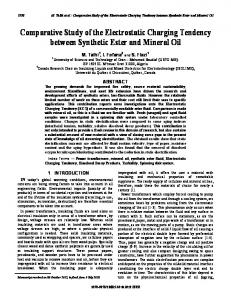
is employed. The algorithm generates a structured tetrahedrical mesh with a quite simple and conceptual process. Each node of the mesh possesses four indices that determine its position in the mesh. This feature of the mesh makes possible a global definition of the elements in the mesh, which avoids the use of excessive memory space. The time needed for mesh generation is very short (several seconds for mesh consisting of millions of elements) and so the user has the possibility to adjust the values of the parameters, in order to optimize the implementation. An example of mesh generated by ARlADNE is shown in Fig. 1.
The external magnetic field The externally applied magnetic field can be introduced in the following ways, at the choice of the user: (i) By introducing the shape of the current-carrying filaments (in the database of the programme). The code calculates and stores the components of the magnetic field, by integrating the Biot-Savart law along the filament. (This choice is time-consuming, but unavoidable for non-cylindrical coils.) (ii) By specifying location and size of cylindrically symmetric coils (as is typical in gyrotrons): Use is made of the data for the components 641 and BJI, as functions of dr0 and rho, of the magnetic field produced by a filamentary circle of radius ro with current I. (This file, generated once for all, is appended to the code.) The magnetic field is obtained, by scaling these data and by superposing the Contributions from the circular filaments that constitute the actual coils. (iii) By introducing the functions, which describe analytically the three components of magnetic field. In all cases, the magnetic field is specified in its own coordinates, which may not necessarily coincide with those of the beam tunnel. Particle Pusher
Fig.1: The mesh on the boundary surface of the 170 GHz gyrotron beam tunnel geometry (designed in FZK) generated by the code.
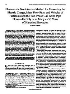
Solver subroutine To solve Laplace and Poisson equations, the code uses the finite element method. For the description of the potential in the region of each tetrahedrical element, quadratic interpolation is applied on the values of the potential of the four vertexes and the six middle points of the edges (totally ten degree of freedom). As a result, the three components of the electric field (the derivatives of the potential) vary linearly inside each tetrahedron. The cost of this feature is the huge order and the huge number of non-zero values of the sparse linear system, generated by the application of the finite element method, as well as the need for computer memory and computational time. Using a parallel successive over relaxation iterative method, based on the domain decomposition technique, solves the huge sparse linear system. In Fig. 2 is presented the computational time needed with the number of processes for the simulation of a l40GHz gyrotron gun with the use of a mesh with 199347 nodes, for 500 iterations. -
The calculation of the macro-electron trajectories is achieved by solving the relativistic equation of motion, using the RungeKutta method with a variable time step. The reliability of these calculations is checked by the satisfaction of several criteria, such us the conservation of total energy, and of magnetic moment in adiabatic motion, etc. The total number of macroelectrons, that describes the beam, is distributed to the available processors of the parallel system and the calculation of the beam dynamics is achieved faster.
Code benchmarks To benchmark the code, at fmt we have studied problems with known analytical solutions. In particular, we have solved the Laplace and the Poisson equations for the configurations of a plane, cylindrical and of a spherical capacitor, as well as for a cylindrical geometry, with a cylindrical surface charge density at a given radius. The numerical results are in a good agreement with the analytical ones. Furthermore, we have tested the panicle-pusher subroutine by calculating the motion of electrons in homogeneous magnetic and electric fields. In addition, we have solved for an elliptical geometry, with and without a charge density, by using ARIADNE and MugNet. Both codes have produced practically identical results. Finally, comparisons have been done between ow code and the codes DAPHNE and ESRAY for the cylindrical gyrotron gun 14OGHz and for the coaxial magnetron injection gun (L70GHz. ZMW), respectively, with very satisfactory agreement. Acknowledgments This work has been supported in part by the Euratom Fusion Programme and the General Secretariat of Research and Technology, Greece. The sponson do not bear any responsibility for the contents of this work. The authors thank Mi. K. Tsakalozos for his work on the graphical user interface.
01 0
2
4
I
8
10
12
11
Number of Processes n
Fig.2: The computational time needed with the number of processes for the simulation of a l40GHz gyrotron gun (designed in CRPP) with a mesh with 199.347 nodes, for 500 iterations.
658
I
16
References [I] W. B. HerrmaMsfeldt, “Electron trajectory program”, SLAC Rep. 226, Stanford Univ., 1979. [2] T. M. Tran, D. R. Whaley, S. Merazzi, and R. Gruber, DAPHNE, A 2D rzrisymmehic electron gun simulation code, 16th Int. Conf. on Infrared and Millimeter Waves, 1991,491-494. [3] S. Illy, and E. Bone, Investigation of beum instabilities in gyrotron oscillutors using !&&?tic theory and panicle-incellsimulotion, I. Plasma Physics, vol. 62, 1999, 95-115.
2004 Joint 29’”Int. Cont. on Infrared and Millimeter Waves and 12’”Int. Conf. on Terahertz Electronics