The 8th 2011 8th International International Conference Conference on on Ubiquitous Ubiquitous Robots Robots and and Ambient Ambient Intelligence Intelligence (URAI (URAI)2011) Nov. 23-26, 2011 in Songdo ConventiA, Incheon, Korea
TC 2-2
The Software Architecture of a Reconfigurable Real-time Onboard Control System for a Small UAV Helicopter Yi-Rui Tang and Yangmin Li† Department of Electromechanical Engineering, University of Macau, Macao SAR 999078, China († Corresponding Author: Tel:+853-8397-4462; E-mail:
[email protected]) Abstract - This paper details the comprehensive software architecture and implementation of an onboard control system developed for a small-scale unmanned aerial vehicle (UAV) helicopter. A PC-104 computer stack is devoted to flight control as well as the interaction with other devices in the onboard system. The consideration to construct the software system is primarily focused on its real-time runtime environment and its competence of flexible reconfiguration. As a result, the system is developed under QNX Real-time Operating System (RTOS). The interaction function of the flight control computer with external devices is built in modules and processes running in a predefined order. The entire software system has been successfully tested in both actual field flights and a hardware-in-the-loop simulation (HILs) environment. The flight results have shown that the software system is competent enough to go on with automatic flight of the UAV helicopter. Keywords - UAV, software system design, onboard control, RTOS, HILs.
1. Introduction Unmanned Aerial Vehicles (UAV) have experienced remarkable development during the past couples of years. They have been helpful to carry out dangerous missions in inaccessible disaster areas for humans, such as a nuclear, a tornado, a flood and an earthquake disaster. There are also abundant examples for both civilian and military applications, e.g., aerial mapping, agricultural monitoring, terrain inspection, traffic surveillance, and air photography. Among multifarious UAV platforms, small UAV helicopter tends to be more suitable for conducting academic research. Researchers can benefit from taking advantage of its low cost as well as natural abilities, including hovering, vertical takeoff and landing, extremely agility and cruise in low speed. To facilitate the development of UAV helicopters, a great number of publications have been contributed to the academic community in categories, such as hardware and software design and integration [1, 2], control algorithms design [3, 4] and visual navigation [5–7]. The onboard software system design is always the significant obstacle to a successful UAV resulting from the critical requirements of real-time operations on multiple tasks. The applications of UAV helicopter take in a series of tasks on data acquisition of multiple sensors and other input/output (I/O) devices, control algorithm and navigation, data fusion and calculations, intercommunication
978-1-4577-0723-0 / 11 / $26.00 ⓒ 2011 IEEE
and synchronization, and so on [8]. Owing to the realtime behavior, the system must be able to respond to all tasks within predictable time limits. A real-time operating system (RTOS) is hence required to provide the base for implementing the onboard hardware. In other words, the onboard software system should be developed under the RTOS supplying a mixture of essential system functions for embedded real-time operations, such as multitasking, threads, rapid context switching, and preemptive scheduling. Almost any of the popular RTOS would be sufficient, such as VxWorks employed in Carnegie Mellon University [9], Linux in University of Southern California [5] and QNX in [6, 8]. However, QNX heavily used in UAV research was chosen due to the stability, embedded real-time capability, and ease of modification [10]. Moreover, more concerns about task-based implementation and I/O management should be devoted to the software system design. This paper presents a comprehensive procedure on developing the onboard software control system of a smallscale UAV helicopter. The developed system exhibits a time-based manner and capability of flexible reconfiguration. This paper is organized as follows. In Section II, the UAV system architecture and functional design are introduced. Section III presents a comprehensive design of onboard software system. Section IV is devoted to the experimental results of the software system tested in both actual field flights and a hardware-in-the-loop simulation (HILs) environment. The paper closes with the conclusions in Section V.
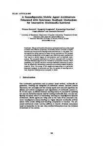
2. Overview of UAV Helicopter System Design 2.1 Description of System Architecture A complete UAV helicopter consists of two selfcontained subsystems including a flight platform and an onboard avionics, and a ground station system. Figure 1 shows the flying UAV helicopter in one of the field tests. The flight platform is mainly utilized to carry the avionics box and other payloads, and is the base of the physical subsystems to be upgraded. The onboard avionics system where the onboard software resides plays the most important role in the whole system. Its functions are to collect essential flight data, communicate with the ground station, and automatically control the UAV helicopter by means of interacting with external devices in real time. The ground station is mainly used to monitor the status of the in-flight UAV and capable of sending human commands as well. The UAV helicopter is designed and de-
- 228 -
Fig. 1 UAV helicopter in flight picted in the following three categories. A. Helicopter Platform It consists of five parts: (a) an airframe; (b) a radio controlled (R/C) receiver that receives the command signals from the R/C transmitter; (c) servo actuators that move the control surface of the helicopter; (d) a heading hold gyro that is applied on the tail rotor control and cancels the rudder trim changes; (e) a battery pack that powers the receiver, servos and gyro sensor. B. Onboard Control System Hardware The onboard control system is principally responsible for the UAV flight control. As a competent candidate, the controller should be able to automatically stabilize the airframe and navigate the helicopter to the destination following the designated trajectory. Helicopter possesses nonlinear, significant coupled, complex and inherent unstable characteristics. The controller design hence becomes a challenging job. Controllers developed based on the proportional-integral-derivative (PID) approach have been successfully applied on UAV helicopters, whereas they can only be used in undemanding environment. Our goal is to design a controller capable of implementing optimized and sophisticated control algorithms. To achieve this goal, some hardware components are required to provide necessary data or information. Our onboard avionics system, as shown in Fig. 2, primarily consists of six parts: (a) an enclosure that is used to contain the onboard hardware components; (b) a PC/104 computer stack that handles the I/O signals and onboard data processing; (c) an inertial measurement unit (IMU) orientation sensor that senses and outputs the states of the in-flight helicopter; (d) a global positioning system (GPS) sensor that provides position information in earth-fixed coordinate system; (e) a sonar altimeter that is especially employed to obtain the height from the ground for landing; (f) a telemetry system that transfers the information from the in-flight helicopter to the ground station via a wireless communication; (g) an electrical power system that is the only source of powering the onboard computer components, sensor and communication hardware; (h) a custom printed circuit board (PCB) that assigns the I/O channels, switches control modes between manual and automatic
Fig. 2 Configuration of the onboard control system control, and prevents the helicopter from danger. C. Ground Station The ground station comprises a workstation computer and a long-range wireless modem. The computer is used for information processing and displaying graphical user interface (GUI) as well. The wireless modem affords the communication between the in-flight helicopter and ground computer. Human commands are sent from the modem in the ground station and received by another end of the paired modems in the helicopter. Vice versa, the helicopter status information (such as attitude and position, etc.) will be transformed to the ground station and displayed in GUI. 2.2 Functional Design of the Control System The helicopter has totally four flight control inputs: Collective pitch denoted by 𝛿𝑐𝑜𝑙 that controls helicopter’s vertical motion, 𝛿𝑙𝑜𝑛𝑔 and 𝛿𝑙𝑎𝑡 are the inputs to the longitudinal and vertical cyclic flapping, and pedal cyclic denoted by 𝛿𝑝𝑒𝑑 that controls yaw motion. The basic functionality of the control system is capable of being effortlessly switched to manual control mode when a malfunction happens to the helicopter during automatic flight. The human pilot can take over the control in time against an air crash. Figure 3 shows the functional architecture of the control system. In automatic control, control blocks are equipped with reconfigurable properties and hence are adaptable to diverse system configurations. The references are provided to the control blocks by either path generation block or experiment-purpose generator block. The latter one is generally used to carry out standard experiments as a straightforward way to get rapid access to the control blocks. Typical input signals can be internally generated by the generator to cater for the particular requirements of experiments. For example, system identification is achieved by using frequencysweep input signals. These are the signals with quasisinusoidal shape of monotonically increasing frequency.
- 229 -
Fig. 3 Functional architecture of control system It is possible to employ experiment-purpose generator to provide this kind of signals. As the alternative, path generation block functions in two modes. Trajectory tracking is performed by the path generation block when mode 1 is selected. A series of sparsely distributed waypoints is sent from ground station and then the block builds a thorough 3D path by computing from the waypoints. Furthermore, the path generation block generates various position and yaw references, with which the helicopter is navigated to the predefined waypoints one by one following the 3D path. In mode 2, the controller is able to reconfigure itself in real-time, which means that any change of latest updated information for path generation block takes effect immediately. For instance, once a new waypoint is set by users in the ground station, the helicopter is navigated to the new destination right away regardless of the current action of trajectory tracking. There are also alternatives working with mode 2 in addition to user command block. Camera based computing system block is mainly utilized for applying the technique of simultaneous localization and mapping (SLAM) which is capable of building up a map within an unknown environment. As the information captured by camera changes, the map gets updated in real time. The path generation block concurrently computes and extracts a path from the map, and provides varying position and yaw input references to the control blocks over time.
3. Software Design of the Onboard System The onboard software system is developed to cyclically operate the onboard hardware following a schedule to realize the autonomous flight. The control of the UAV helicopter is typically a demanding timely behavior and needs to handle multiple processes. Each process runs on a predefined schedule and is assigned to the corresponding I/O task dealing with the onboard hardware. 3.1 Software System Architecture and Processes The designed software should be able to meet the rigorously real-time requirement so as to ensure the system’s response to the processes within predictable time limits. A real-time operating system (RTOS) is hence required
Fig. 4 Architecture of the onboard software system to provide the base for implementing the onboard hardware. In this research, the onboard software system is developed under the RTOS called QNX Neutrino which has the capabilities of multitasking, threads, rapid context switching, and preemptive scheduling. To realize the autonomous flight, the software system is designed to implement hardware operations through five principal processes running at different rates, namely IMU, GPS, servo signal, data logging, wireless communication processes. The processes and event sequences of the system are described in Fig. 4. A. IMU Process The IMU process is employed to access the Microstrain 3DM-GX2 IMU sensor and retrieve the helicopter’s state information, such as the Euler angles, angular rates and accelerations, at a rate of 100 Hz. The IMU utilizes a built-in onboard processor to continuously execute calculation cycles. The duration of each calculation cycle that determines the data output rate (inverse of the duration) can be changed by storing an integer value in the specified EEPROM address. Thus, data output rate is capable of adjusting. The valid range for the Microstrain IMU is from 1Hz to 300Hz. Based on the time arrangement for each process in the software system, a data output rate of 100 Hz is sufficient for the IMU data acquisition. The communication with the IMU sensor is setup by a serial connection and follows the 3DM-GX2 Data Communications Protocol [11]. In the design of the IMU process, the serial COM port is configured with a baud rate of 115200 bps and the communication is in polled mode. The PC/104 computer issues a single byte command 0xC8 which is sent to IMU for requesting the IMU output data including accelerations, angular rates and orientation matrix. The output data is transmitted in the form of 67 bytes binary. Each
- 230 -
output data is a floating-point number that consists of 4 bytes binary conforming to the IEEE-754 format. Since the data are transmitted in the order of big endian, the PC/104 computer receives the Most Significant Byte (MSB) of the data first which is stored at the lowest storage address and the Least Significant Byte (LSB) last which is stored at the highest storage address. Whereas, PC/104 computer is a little endian system in which the MSB is at the highest storage address and the LSB is at the lowest address. In order to properly present the received floating-point number in the PC/104 system, each byte of a floating-point number (4 bytes) received from the IMU is stored at the storage address in the reversed order (e.g. MSB of each 4 bytes is stored in highest address, LSB is in lowest address). The values of accelerations and angular rates in body-fixed axes can be obtained from IMU directly after solving the floating-point data problems. However, the Euler angles are derived from the rotation matrix in terms of their calculation algorithms. The orientation information output by the IMU is in the form of 3 × 3 rotation matrix. B. GPS Process The GPS process is responsible for achieving position information of the helicopter. After establishing the serial communication connection with GPS receiver, a shared memory location is created for storing GPS data packets. The process helps to read and parse data from GPS receiver, and continuously commit the data to shared memory. The data extracted includes the values of longitude 𝑃𝑥 , latitude 𝑃𝑦 , altitude 𝑃𝑧 , number of satellites and a count number. The combination of first three values provides the location of the helicopter in local north, east, down (NED) coordinates. The counter number is as the identification of data packet and increases with any freshly received data string from the receiver. This allows the process accessing the GPS shared memory to retrieve the latest information available. However, the information attained directly from GPS receiver is not good enough for control purpose. The extended Kalman filter is hence dedicated to the improvement of GPS measurement accuracy as well as the attenuation of noises. C. Servo Signal Process The servo signal process is mainly responsible for generating control signals with the support of the C/T card in the PC/104 stack. Besides, it is also used to measure PWM signals from the R/C receiver for particular flight tests. The PWM signal is exactly used to control the rotation of the onboard servomotor’s shaft. The position of the shaft is determined by the width of high level PWM signal, 𝑊 shown in Fig. 5. In general, the deflections of the servomotor are described by the percentage of the high level length relative to the PWM signal period which is known as a duty cycle. The frequency of the PWM signals generated in the onboard control system is about 70Hz. The PWM signal is thus with a period of 1/70 seconds. Two essential registers including the Master Mode
Fig. 5 PWM signal timing diagram
Fig. 6 PWM signal counting diagram
Register (MMR) and the Counter Mode Register (CMR) must be programmed prior to using the C/T card. There are two counter/timer chips in the C/T card and each chip provides five counters. Each chip has a MMR that defines the entire counters’ characteristics in this chip. The CMR is employed to program the operating mode of each counter, such as counter source, gating control, count direction, cycle mode, and so on. A high-frequency count source is provided to measure the PWM signals. Each chip provides five internal count sources with different frequencies. By programming the CMR, the C/T card selects a count source with the frequency of 400 KHz and the gating control mode of activating high level PWM signals. For control purpose, the variant PWM signals are generated by setting the corresponding values of the duty cycle. However, to measure a PWM signal, it needs to read out the value stored in the hold register where the counted number of the high level PWM resides. Figure 6 illustrates how a count source lends itself to measure the PWM signal. The count source continuously generates the 400 KHz pulses. The counter is triggered to count the pulses when it meets the high level of the PWM signal. The count process is accomplished when the signal is switched from the high to the low level. The number of counted pulses (CP) is stored in the hold register. D. Data Logging Process The data logging process is responsible for writing and logging data to the storage CF card during operation of the helicopter. The process is dedicated to collecting the time, orientation, accelerations, angular rates, and pilot’s control inputs from the shared memory and to writing them to a text file in the form of binary in the CF card. Note that data writing speed in binary is much faster than in character. Every time, the recorded data are constructed to be a user-defined data structure in terms of the information types of the flight data. A detailed data structure includes 17 information types, namely the roll, pitch and yaw angles, angular rates in X, Y and Z directions,
- 231 -
accelerations in X, Y and Z, duty cycles of the PWM signals measured in seven counters in C/T card, and the time when all these events occur. The data are written to the CF card in the form of data structure every time and the writing process happens at approximately 1 Hz. There are in total 50 data sets required to be written and stored in the CF card in every writing process. Due to the text file is in the binary format, another program is developed to parse the binary file and save the data in a new commaseparated values (CSV) file which can be recognized and opened by Microsoft Excel, and effortlessly imported by Matlab for further analysis. E. Wireless Communication Process The wireless communication process is responsible for reporting the in-flight helicopter’s status to the ground station for monitoring. The flight data of helicopter states are transmitted from the onboard part of duplex wireless modems to the one installed in the ground station. The data transmission is in the form of a packet. The onboard wireless modem is connected to the onboard computer via serial port. The data packet is hence comprised of bytes. During data transmission, the latency, that is from the time data are transmitted until received increases with the number of bytes in data packet. The data rate for transmission is set to be 19,200 bps in the duplex modems which are capable of transmitting 2.4 kilo bytes data in every second. For a single data transmission, the onboard computer spends the first 35 ms initializing the channel. During this period, it sends flight data to the wireless modem and stores them in the buffer. After 35 ms, the data are assembled into packet and transmitted over air to the ground station. 3.2 Control Implementation To perform in-flight tasks, it is required that the onboard system cyclically executes the processes at a fast and invariable rate. The system period is set to 20 ms upon the consideration of various timely ingredients. The QNX library including thread, messages passing, timer and thread synchronization are utilized during the programming. In QNX, the execution of each process is performed in individual thread. The threads are capable of running simultaneously in the program and accessing to the shared memory for data exchange with the external hardware. When a pulse is received, the thread starts to be executed. At the end of the execution, a message is sent by the thread to notify the accomplishment of the process. All the threads are scheduled to work separately by a timer in QNX and this timer is also used to trigger the overall loop program. In the execution cycle, the program starts functioning once the timer pulse is received. After executing the threads, the processes are held and wait for the arrival of new pulse to trigger the next cycle. A linear quadratic regulator (LQR) controller is developed and implemented in the control system. The block diagram of the controller structure is shown in Fig. 7. The control software schedules multiple processes in the form of threads to perform I/O operations with on-
Fig. 7 Block diagram of controller structure board sensors and places the acquired data in the block of shared variables. The necessary sensor data (e.g. positions and velocities) are picked out for calculation according to the developed control algorithms. The calculated values are committed to the shared memory for being retrieved by the servo signal process to control the helicopter. The shadowed triangles (see Fig. 7) are controller gains whose values are obtained in Hardware-inthe-loop simulation (HILs). The HILs is known as an efficient way with high-fidelity to validate the control algorithms and examine the feasibility of integrated software control system [12]. In the control system development, the gain values are first attained with off-line simulation tool Matlab/simulink and then validated with controller hardware in HILs. The tuned values are eventually employed in the software controller programming to perform real flight tasks.
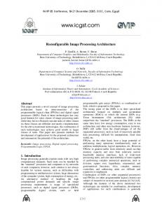
4. Experiments and Results As the onboard PC/104 computer implements sophisticated LQR control algorithms, more working load of the software system needs to be handled. The onboard control system delivers a satisfactory performance, especially in the computation of floating point numbers. In the overall software system testing, the processor is lightly loaded and the system consumes only about 5% of the CPU time. Even for a more rigorous and worse case, the available computing power is not less than 45%. The low CPU usage rate makes the onboard software system be competent to perform in-flight tasks. The onboard control system is tested in HILs system before implementing the actual automatic flight. During testing, the HILs helps to detect many unforeseen errors, faults, and malfunctions of the control system so that the system failure can be avoided to a great extent in actual flights. Both the simulation and actual flight results are presented in this section. A number of experiments are conducted with the HILs system, whereas only a typical example is provided in this section. The control system is tested in a risky and hazardous situation. The helicopter experiences a sudden disturbance when it is performing the flights of trajectory tracking. A perturbation of 1 m/s is injected to the helicopter along the Y body axis at the 50th second. The responses of the helicopter are illustrated in Fig. 8. The results clearly indicate that the control system enables the
- 232 -
Acknowledgement
14 Px Py Pz
12
This work was supported by Research Committee of University of Macau under Grant No.:MYRG183(Y1L3)-FST11-LYM and the Macao Science and Technology Development Fund under Grant No.:016/2008/A1.
10
Position (m)
8 6 4 2
References
0 −2 −4 −6
0
10
20
30
40
50 Time (s)
60
70
80
90
100
Fig. 8 Helicopter position under perturbation injected to the Y body axis at the 50th second Reference Measured
10
Altitude (m)
8 10
6
5
4
0 14
2 12
10
8
6
Northing (m)
Easting (m)
0 4
2
0
−2
−2
Fig. 9 Trajectory tracking of the UAV helicopter.
helicopter to quickly recover from fluctuations. Figure 9 shows the results when the UAV helicopter is working in mode 1 and performing trajectory tracking in actual field flight tests. The waypoint sequence is sent from the ground station and then the control system generates a 3D path. The helicopter is commanded to take off vertically and navigated to fly following the path. The resulting positions of the helicopter are compared with the generated 3D reference path by the onboard control system in Fig. 9.
5. Conclusions This paper has completely described the software architecture of the onboard flight control system for the UAV helicopter. The control system has been developed and implemented in flight tests. The designed software system is capable of accurately scheduling multiple onboard processes and periodically operating I/O devices under the QNX RTOS. The advanced and sophisticated control algorithms have been applied on the control system and implemented successfully. The control system has been validated with both HILs system and actual flight experiments. Future work will focus on investigating distributed systems so as to facilitate the deployment of cooperative control of multiple UAVs.
[1] R. D. Garcia, A Modular Onboard Processing System for Small Unmanned Vehicles, M.Sc. Thesis, University of South Florida, Tampa, 2006. [2] S. Saripalli, J. M. Roberts, P. I.Corke, G. Buskey and G. S. Sukhatme, “A Tale of Two Helicopters,” Proc. of IEEE/RSJ Int. Conf. on Intell. Robots and Systems(IROS), Las Vegas, USA, pp. 805-810, Oct. 27-31, 2003. [3] D. Y. Maharaj, The application of non-linear control theory to robust helicopter flight control, Ph.D. Thesis, Dept of Aeronautics, Imperial College of Science, Technology and Medicine, 1994. [4] K. Peng, G. Cai, B. M. Chen, M. Dong, K. Y. Lum and T. H. Lee, “Design and implementation of an autonomous flight control law for a UAV he⁀ licopter,” Automatica, Vol. 45, No.10, pp. 23332338, October 2009. [5] L. Mejias, S. Saripalli, P. Campoy and G. S. Sukhatme, “Visual Servoing of an Autonomous Helicopter in Urban Areas using Feature Tracking,” ⁀Journal of Field Robotics, Vol. 23, No.3, pp. 185199, 2006. [6] S. E. Hrabar, Vision-Based 3D Navigation for an Autonomous Helicopter, Ph.D. Thesis, University of Southern California, 2006. [7] S. Hrabar and G. S. Sukhatme, “Omnidirectional vision for an autonomous helicopter,” Proc. of the IEEE Int. Conf. on Robotics and Automation, pp. 558-563, Sept. 2003. [8] M. Dong, B. M. Chen, G. Cai, and K. Peng, “Development of a real-time onboard and ground station software system for a UAV helicopter,” Journal of Aerospace Computing, Information, and Communication, Vol. 4, pp. 933-955, 2007. [9] B. Mettler, M. B. Tischler and T. Kanade, “System Identification Modeling of a Small-Scale Unmanned Helicopter,” Journal of the American Helicopter Society, Vol. 47, No.1, 2002. [10] R. Krten, Getting started with QNX Neutrino 2 - A Guide for Real-time Programmers, Kanata Ontario: PARSE Software Devices, 1999. [11] Microstrain, 3DM-GX2TM Data Communications Protocol, Williston, VT: Microstrain, Inc., 2007. [12] G. Cai, B. M. Chen, T. H. Lee and M. Dong, “Design and Implementation of a Hardware-In-TheLoop Simulation System for Small-Scale UAV Helicopters,” Mechatronics, Vol. 19, 2009, pp. 10571066.
- 233 -