The composition of 3D presentations is a ... included so as to provide a global treatment to virtual (3D ... Virtual presentations graphically represent real-life.
The Storage and Querying of 3D Objects for the Dynamic Composition of VRML Worlds
Alex Vakaloudis, Babis Theodoulidis Timelab, Dept. of Computation UMIST {alvak, babis}@sna.co.umist.ac.uk
Abstract The composition of 3D presentations is a complicated procedure partly facilitated by the introduction of VRML. VRML does not yet support 3D object storage and querying thus introducing limitations to object reusability. Presentations have to be built from scratch while the necessary information exists already from previous work. This paper presents a method to address this issue by providing the
1. Introduction The composition of 3D presentations is a complicated procedure where the developer has to specify the graphical and behavioural characteristics of the participating objects. Virtual Reality Modelling Language (VRML), has eased this operation by introducing a simple mechanism for the representation of interactive 3D graphics and worlds delivered across the Internet [1]. By examining the number of VRML browsers, authoring tools and worlds we can safely assume that it has been adopted as the typical way for constructing virtual presentations [4]. Nevertheless, even with the use of VRML, the following limitations still exist in the composition process: • Restricted object reusability The virtual worlds developer has not enough support (only the PROTO node in VRML) for reusing objects. Thus he builds new virtual presentations almost from scratch while the necessary information may already be available from previous work. • No link to the non-graphical attributes of objects Virtual presentations graphically represent real-life objects which have a series of non-graphical attributes. There is no connection to these parameters whose values might be decisive for the inclusion of an object into a world (e.g. “include the buildings constructed by ‘Halifax’ only”). This paper tries to address these two problems. We present a technique for the storage, querying and manipulation of 3D objects, which increases object
functionality for (re)composing 3D interactive presentations. The participating objects are selected through spatiotemporal criteria. The temporal element is included so as to provide a global treatment to virtual (3D space+time) objects. The objects retrieved this way, form a repository and are further transformed in order to satisfy the requirements of the composed presentation. The entire framework complies with the VRML standard[2]).
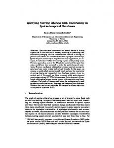
reusability. A permanent repository of objects is maintained and the developer selects the ones that fit to his needs. Virtual worlds are therefore composed dynamically by objects that satisfy the user’s spatiotemporal criteria. The spatial term refers to the 3D characteristics (geometry, position and visual appearance). The temporal element is introduced because it is a fundamental part of a virtual environment. The entire framework complies with the VRML standard. Selection
Database Repository
Scenario Formulation
Selected Spatiotemporal Objects
Mapping
Processed Spatiotemporal Objects
VRML Source Code
Figure 1: The route from stored objects to 3D presentations Fig. 1 demonstrates the three steps of composing a virtual presentation, namely: 1.Selection Querying of the database to get the objects that should be included in the repository. More than one query may be performed. 2. Scenario Formulation Transformations on these objects (change spatial values, move, scale) so as to achieve better representation and interaction. 3. Mapping The mapping to VRML code.
We just outlined a mechanism that goes from storing 3D Spatiotemporal objects to dynamic virtual world construction through reusing these objects. The rest of the paper is organised as follows: Next we present the structural model for storing 3D Spatiotemporal Objects in a database repository. In section 3 we propose a set of operators for the selection and manipulation of these objects. Then an example is given in order to explain the applicability of the approach. Finally we summarise related work and conclude by giving pointers to future work.
2. Specification of 3D Spatiotemporal Objects In this section we discuss the basic concepts of modelling 3D Spatiotemporal entities within a database repository. Let us consider a primitive 3D object such as a box, sphere, cylinder or cone. Its spatial characteristics can be easily modelled with VRML. Using the VRML method, different attributes are used to describe the object’s appearance, geometry and placement. Therefore a 3D Object VObject can be defined as Definition: A VObject is a tuple: VObject {id, geometry, appearance, placement} where geometry models the geometry of the object, appearance its appearance and placement its positioning. The latter one is extended by Orientation, a 3D vector that points to the top side of the object, if such exists. Here, we extend this modelling approach by incorporating temporal features. First we give the definition of the VTime concept: Definition: A Timestamp VTime marks the valid time and the transaction time for a recording and also connects to the previous recording. VTime: {(valid_time, transaction_time), (mode, value)} The first pair timestamps the spatial attribute’s state. Both valid time (i.e. particular state’s time) and transaction time (time of the recording) are registered. The second pair connects two successive recorded states and so the user can interpolate into the period they form and thus extract a non-explicitly recorded situation. The arguments to the interpolation procedure are mode and value which specify the way mutation has occurred (e.g. linear, acceleration, cyclic mode). The application developer can choose and use the set of modes appropriate for a specific application. The requirement for the inclusion of trend features in the temporal semantics derives from the fact that 3D
Spatiotemporal objects have continuous behavioural characteristics. Because they represent real-life objects (and not their abstraction as it is the case for the 2D domain) they simply cannot disappear. They move, rotate change shape and appearance but always maintain their existence even in more than one formation. Steel and glass for example are used to build a car and after twenty years they may be part of a scrap yard. The material exists forever even if it changes patterns (steel-car’s framework, scrap metal). The combination of VObject and VTime leads us to the definition of VTObject, the concept describing the storable 3D spatiotemporal primitive Object: Definition: A Spatiotemporal Object VTObject is a VObject whose attributes have the VTime timestamp attached on them. VTObject: VObject x VTime ⇔ VTObject: {id, (geometry, VTime) (appearance, VTime) (placement, VTime)} Having defined the primitive spatiotemporal object, the next task is to define a grouping mechanism in order to represent real-life objects and their links to non-spatial attributes. To achieve this we first introduce the notion of Index. Definition: An Index describes the relationship of a graphical object with its non-spatial attributes. More specifically it links the VTObject.id with the table (Table.Name) and the entry (Table.KeyField.id) where the non-spatial attributes of the object are described. Index:{cVTObject.id, pVTObject.id, Table.Name, Table.KeyField.id, VTime, Granularity} where: cVTObject.id, pVTObject.id are VTObject ids, Table.name is the name of the table where the object is classified, Table.KeyField.id is the key value in that table, VTime is the timestamp of the tuple, Granularity is the granularity of all the temporal values associated with the object The first VTObject.id points to a primitive object while the second to its parent, which also has a placement and maybe a specific appearance. (e.g. five cylinders comprise a table; a table and two chairs are inside a room etc. This part-of relationship can change (somebody moved the chair outside the room) and hence is considered to be temporal. TableName and TableKeyField specify the real-life object that the VTObject graphically describes. An example of Index table is given in the example section. Figure 2 demonstrates the use of Index. It serves as a bridge between the spatial and the non-spatial part of an application. It contains references to the spatial and the non-spatial attributes of the same object.
Non-Spatial part
Index table
Spatial part
Table 1 Table1.KeyField (Other Data)
Index entries cVTObject.id, pVTObject.id VTime Granularity
VTObject1 VTObject1.id (Spatial Description)
Table.Name Table N TableN.KeyField (Other Data)
Table.KeyField
VTObjectN VTObjectN.id (Spatial Description)
Figure 2: The general view of the modelling approach: The three different parts of an application
3. Operations Objects
on
3D
Spatiotemporal
3.1 Query Operations Storing objects in the Spatiotemporal repository is meaningless unless we also provide a method for extracting the appropriate information. It consists of a set of temporal, conventional spatial (i.e. ones derived from the 3D domain and defined again here), 3D specialised spatial (that use specific 3D features) and spatiotemporal operators briefly analysed in this section. The selection of objects is mainly done according to spatiotemporal criteria. However, common attribute (i.e. non-spatial) parameters may also come into play. A query example mixing spatiotemporal and attribute criteria is “Give the thick books printed by McGraw Hill during 1998”. “Thick” refers to geometry while “McGraw Hill” is attribute information. The most preferable implementation technique that unifies spatial and non-spatial querying is an extension to SQL (e.g. implemented using Oracle PL/SQL). This way we can ask for attribute information and at same time by using the operators below, to investigate the spatiotemporal repository. We first introduce two temporal operators, which select a snapshot of a VTObject and examine if a VTObject exists under a certain form at a time t respectively. • [VObject] at (VTObject, VTime) (Returns VTObject corresponding to VTObject at VTime) • [boolean] exists (VTObject, VTime, Table.Name) (Check if VTObject exists in a certain form at VTime)
We see that the transition from the spatiotemporal to the spatial domain is smooth because a VObject is produced by applying the at operator to its respective VTObject. Spatial operators have been extensively researched in the 2D domain [10]. They are also employed here: • [boolean] equal (VObject, VObject) (The two objects consist of the same parts) • [boolean] disjoint (VObject, VObject) (The two objects do not have any common parts) • [boolean] meet (VObject, VObject) (Some parts of the objects meet while the rest disjoint) • [boolean] in (VObject, VObject) (One object is entirely inside the other) • [boolean] overlap (VObject, VObject) (There exist parts that overlap, in and disjoint) Briefly, the definition of disjoint is given: Disjoint (VTOject1, VTObject2) ⇔ VTOject1 and VTObject2 have no common parts. If VTOject1, VTObject2 are not primitive objects, this is delegated to all their children. Apart from these conventional predicates virtual worlds offer opportunities for full interaction. In the 3D domain, the user becomes an integral part of the overall setting. With the 2D maps he remains external to the environment whereas in 3D worlds he may navigate in all three dimensions. Moving inside the world, his positioning influences the way he conceptualises the relationships among objects. Figure 3 exemplifies this fact. The two boxes have stable positions. Nevertheless Viewer 1 believes that Box 2 is behind Box 2. On the contrary, Viewer 2 assumes that Box2 is in front of Box 1. A third viewer (viewer 3) thinks that Box 1 is on the left of Box 2.
Viewer 1
Viewer 2 Box 1
Box 2
Viewer 3
Figure 3: Different Viewpoints drive to understanding of different relationships To capture all these occurrences we introduce the concept of viewpoint: Definition: Viewpoint represents the user’s view as Viewpoint {position, orientation, direction}
where
position is a Cartesian 3D point orientation is a Cartesian 3D point direction is a Cartesian 3D point
Viewpoint consists of three 3D points. The first one marks the user’s position, the second his orientation and the third his viewing direction. Viewpoint is employed as an argument to the following Viewpoint dependent operators: • [true, false, indefinite] infront (VObject, VObject, Viewpoint) (The first object is in front of the second one as seen from the viewer in Viewpoint position) • [true, false, indefinite] behind (VObject, VObject, Viewpoint) (The first object is behind the second one as seen from the viewer in Viewpoint position) • [true, false, indefinite] up (VObject, VObject, Viewpoint) (The first object is above the second one as seen from the viewer in Viewpoint position) • [true, false, indefinite] below (VObject, VObject, Viewpoint) (The first object is below the second as seen from the viewer in Viewpoint position) • [true, false, indefinite] left (VObject, VObject, Viewpoint) (The first object is on the left of the second as seen from the viewer in Viewpoint position) • [true, false, indefinite] right (VObject, VObject, Viewpoint) (The first object is on the right of the second as seen from the viewer in Viewpoint position) The indefinite result occurs when non-visible objects are examined. The assumption made here is that the user can only compare objects that are on his visible part of world which is determined by the values of the Viewpoint vectors. Apart from the viewpoint operators there is a need to cater for relationships independent from the user’s viewpoint. Some 3D objects have a certain directioning specified by the Orientation vector. For example “a glass is on the table” no matter where the viewer is. The functions addressing this matter are: • [true, false, indefinite] upon (VObject, VObject) (The Orientation vector indicates that the first object is upon the second) • [true, false, indefinite] beneath (VObject, VObject) (The Orientation vector indicates that the first object is beneath the second) Finally we include a set of spatiotemporal operators examining spatial mutations over a period of time. • [true, false, indefinite] grow (VTObject, VTime, VTime) (Volume grows within the temporal period)
• [true, false, indefinite] shrink (VTObject, VTime, VTime) (Volume decreases within the temporal period) • [true, false, indefinite] approach (VTObject, Viewpoint, VTime, VTime) (The distance between the viewer and the object increases within the temporal period) • [true, false, indefinite] leave (VObject, Viewpoint, VTime, VTime) (The distance between the viewer and the object decreases within the temporal period) The operators listed here describe generic functions. The potential developer may combine them to compose complicated and application specific predicates. For example: between (VObject1, VObject2, VObject3, Viewpoint): (VObject1 is Between VObject2 and VObject3) infront (VObject1, VObject2, Viewpoint) AND infront (VObject1, VObject2, Viewpoint) over (VObject1, VObject2): (VObject1 is Over VObject2 e.g. a glass is Over the table) Upon (VObject1, VObject2) AND meet (VObject1, VObject2)
3.2 Transformations The objects selected by the querying procedure have certain spatial and temporal characteristics that are not always compatible with nature of the application. For example the temporal period of concern might be a few centuries or the selected objects may be spread over miles of space. Such incidents forbid objects from being directly presentable (e.g. real-time presentation). Even more, an object can be stored as pattern and be populated in order to appear in multiple instances. Hence, it is necessary for the objects to go through some processing so as to become suitable for presentation. The operators that apply for the refinement process are: • scale (VTObject, timefactor, spacefactor) where timefactor and spacefactor are the factors for scaling in time and space respectively Shrinks or magnifies an object in time and space according to the needs of the application • rotate (VTObject,, rotatefactor) where rotatefactor are the factor for the rotation Rotates an object in the 3D space. • clone (VTObject, instances, spatial_distance, temporal_distance) where instances is the number of populating instances of VTObject and spatial_distance temporal_distance, their distance in space and time respectively. (Populates an object used as a pattern e.g. Fill the room with computers by populating the one designed in VRML.)
• translate (VTObject, space_move, time_move) where space_move and time_move is the new position in space and time respectively (Moves the object to a desired spatiotemporal position) • mode (VTObject, Viewpoint, click) where viewpoint is the Viewpoint VRML Node associated with the VTObject, and click the Hyperlink address to go to when clicking on it. This is a first step towards interaction with a set of user and application events that is left as future work. Currently mode supports the inclusion of a Viewpoint for the VTObject and a TouchSensor that hyperlinks to an Internet address.
4. An Illustrating Example Suppose we want create a collection of 3D presentations with the life in UMIST demonstrating the evolution of the campus and the actions of staff and students. Apparently a number of 3D objects will be common in some of them. At the same time, we wish to select the participating objects by graphical and other attribute criteria. The database schema employed is shown if fig. 4. It contains the names of the tables only as their fields are trivial in this case. We observe the segregation of non-spatial and spatial data, which are linked via the index table entries (fig.5). Non-spatial Part Staff Department
University Building
Room
Lab
Computer
Room
Yard
Snow
attributes of the object while pVTObject.id encapsulates the part of relationships by pointing to the parent object. Hence, Computer P2 and Door D1 are parts of Lab H13. When the user requires the description of a parent object (e.g. H13), the data returned contain its spatial description but also the ones of its children. Field VTime refers to the time of the state of the object while TTime is the actual time of the recording. Table and KeyField fields link to the non-spatial attribute of a graphical object. For the example of a lab these might be its name, its type and its responsible lecturer. c.id 1 13 14 2 15 3 4 5 6 7 8 9 10 11 12 16 17
.id -1 (root) 1 1 1 1 2 2 -1 3 2 7 1 -1 1 1 7 2
Index Table University Department Department Building Building Room Room Computer Computer Lab Computer Yard Snow Car Car Door Door
KeyField UMIST Computation EE&E MSS MB M3 M13 P1 P1 H13 P2 Union sq. S1 SBU995X CUE BALL D1 D2
VTime 01/011900 31/12/1970 15/07/1960 22/11/1968 31/03/1902 15/041968 15/05/1968 30/04/98 30/04/98 31/05/1968 12/12/1997 01/10/1920 30/04/98 31/10/1981 22/02/1992 01/01/1995 01/10/1995
TTime 30/04/98 30/04/98 30/04/98 30/04/98 30/04/98 30/04/98 30/04/98 30/04/98 30/04/98 30/04/98 30/04/98 30/04/98 30/04/98 30/04/98 30/04/98 30/04/98 30/04/98
Gran Day Day Day Day Day Day Day Day Day Day Day Day Day Day Day Day Day
Figure 5: The UMIST database Index entries To illustrate the applicability of the model and the operators presented in the two previous sections, we are going to compose two 3D presentations following the three-step approach of fig.1.
Car
4.1 A Winter Day at UMIST: Index
Spatial Part
Index VObject.id VObject.id Table.Name Table.KeyField VTime
Box
Cone
Position
Cylinder
Sphere
Appearance
Figure 4: The UMIST Database schema The Index table entries for this database are shown in Fig.5. Field cVTObject.id links to the spatial
The first one is to show the UMIST campus during a winter day when the snow is falling and the campus has winter colours: A1. Collect the UMIST description for 19/02/98: Search the Index table and return all the children of UMIST for 19/02/98. A2. Collect additional background Objects: Search for Snow with density 12. B1. Specify Building Viewpoint Add Viewpoint infront of every Building B2. Specify Building contents appearance Add Hyperlink to the retrieved Lab object. Add one Viewpoint for each Room and Lab. B3. Transform the only Snow Object: Repeat it 1000 times with spacing 10cm for each instance (spatial repetition) Scale it so as to have speed 10m/sec (temporal scaling)
Repeat it for ever (temporal repetition) B4. Transform the Yard Object: Set its colour to white. C1. Map these objects to VRML Code and present it
4.2 Professor Brown’s Biography This to create the biography of Professor Brown. It assumes that besides the VRML browser there is a second window for displaying non-graphical information. A1. Collect all attribute information about Brown A2. Collect all Room and Lab objects related to Brown A3. Collect the contents for each Room A4. Collect the large items of each Lab object B1. Specify the tabular Window B2. Specify Lab and Room B3. Set the limits of this presentation Scale the duration to 2:00. C1. Map these objects to VRML Code and present it
5. Related Work The necessity for the persistent storage of VRML Objects has been acknowledged by VAG [6], the governing body for VRML, which established the Database Working Group [7]. Oracle have submitted a proposal with Java mappings to persistence [8]. Another approach linking VRML code to Databases is described in [9] where the source code (text) for the VRML Objects is stored and used for the construction of Virtual Worlds through non-graphical criteria only The customisation of 3D Objects is a facility offered by most of the graphical editors. The visual characteristics of an object can be adjusted by applying operators as the ones of section 3.2 [16][17]. In the spatiotemporal databases domain, researchers are intergrating spatial and temporal concepts [14]. Worboys introduces the ST-simplex, a spatiotemporal structure that supports 3D space and 2D time [11]. Moving points and regions [12] is another spatiotemporal structure that conceptualises lines as points evolving over time. De Cambray employs behavioural functions to link two explicitly known states of 3D objects [13] thus maintaining continuous knowledge about object status. Hamre [15] uses a fourdimensional structure to model points in the 3D space and time field.
6. Conclusions We introduced a method that assists the composition of 3D presentations by (re)using objects queried from a database repository. The object selection is delivered by applying a set of spatial, temporal and spatiotemporal operators to the 3D
Spatiotemporal Objects. To make full use of the special characteristics of the 3D domain we employed the user’s viewpoint as a query argument. The objects retrieved are refined and finally produce a source file in VRML’97 format. This way the presentation becomes accessible through Internet browsers. The proposed technique not only accelerates the composition procedure but also ensures that the participating objects fulfil the developer’s graphical and non-graphical criteria. Future work involves the specification of an event model. Events generated by the user and the application will be captured and trigger further actions inside the 3D environment.
7. References [1] Using Java to interact with geo-referenced VRML within a virtual field course K. Moore, J.Dykes, J.Wood, ICA Visualisation Commission meeting, Stockholm 1997. [2] International Standard ISO/IEC 14772-1:1997. [3] VRML’97 Specification, a copy exists at http://dream.leeds.ac.uk/stu/VRML97/ [4] The VRML Repository, San Diego SuperComputer Center http://www.sdsc.edu/vrml/repository.html [5] Why Database support for VRML, K. Walczak, Basic information track for Computational science, 1997 [6] The VRML Architecture Group http://vag.vrml.org [7] The VRML Database Working Group http://www.vrml.org/WorkingGroups/dbwork/ [8] VRML Data Repository API, Oracle proposal 1997 http://www.olab.com/vrml/overview.html [9] Spatial Views and LOD-Based Access Control in VRMLobject Databases M.Kamiura, H. Oiso, K. Tajima, K. Tanaka, Springer Lecture Notes in Computer Science Vol. 1274. [10] A topological data model for spatial databases, M. Egenhofer, A. Frank, J. Jackson, 1989 Springer Lecture Notes in Computer Science Vol. 409. [11] A Unified Model for Spatial and Temporal Information, M. Worboys, The Computer Journal, No. 1 1994. [12] A Foundation for representing and querying Spatiotemporal Data, R-H Guting, M. Bohlen, N. Lorenzos, M Schneider, C. Jensen, M. Vazirgiannis, M. Erwig, Chrorochronos technical meeting 30/04/98. [13] Time as a geometric dimension for modelling the evolution of entities: a 3D approach, T.S. Yeah, B. de Cambray, 1992. [14] Chrorochronos project Newsletter, No.2 30/04/98. [15] An Object-Oriented Conceptual Model for Measured and Derived Data Varying in 3D Space and Time, T. Hamre Int. Symposium on Spatial Data Handling 1994. [16] Virtual Data Visualiser, R. van Teylingen, W. Ribasly, L. van der Mast Vol. 3, IEEE Transactions in Visualisation and Computer Graphics No.1 1997. [17] Formal Specification of Interactive Graphics programming Languages, W. Mallgen, MIT Press 1982.