[9], [10] at the appropriate time and place. We propose ..... descriptions were presented by Cockburn in [4]. El-Attar and .... Edinburgh International. Conference ...
Sep 5, 2011 ... At Point B, the R410A refrigerant of 0.1MPa boils at a ... Mollier chart. Si-18 ...
Chart is therefore sometimes referred to as "Pressure-enthalpy.
Keywords: essential, meta-model, specification model, textual, use case. ... nowadays use cases can be used by other processes that take different software ... business use case [9, 15] describes the business context or even the idealized.
Use Case Scenarios can help drive downstream development via automatically
generated test cases, activity diagrams, sequence diagrams and much more.
introduce a coverage language and an algorithm for automatic test generation. ..... call should be tested without sending an email at any point of the test run:.
ever, that this would be very problematic for overall software development productiv- ity. ... COSMIC-FFP method to measure software documented using use case model. As a ..... Consulting Inc., 2004. www.softwaremetrics.com. [Mk98].
CIMOSA [2], GERAM [4], IDEF suite, GRAI, DoD. [3], MDA [10]), standards (ISO 14258, ..... How to Survive in the Jungle of En- terprise Architecture Frameworks.
Online English edition of the Chinese language journal ... 1 Transportation Research Center, School of Naval Architecture, Ocean and Civil ... 3 Department of Urban and Regional Planning, University of Florida, Gainesville, FL 32611, USA.
May 20, 2012 - A dedicated software tool supports the automation of the proposed approach including the automated generation of use case diagrams and ...
course which is delivered in a distance learning Maths course. .... terms introduced at a higher level of detail (e.g. a case study guide accompanies a case study which is .... In Proceedings of the 11th International World Wide Web Conference.
Metadata for learning resources has become a widely discussed research topic, but the concept is ..... o A TV channel for broadcasting lectures o A chat room for ...
COSMIC-FFP method to measure software documented using use case model. As a ..... solutions supporting essential business activities of a big corporation.
automation is illustrated in a case study of an Automated. Teller Machine (ATM) System. The UCDA tool increases design productivity, reduces time-to-market ...
is closely guarded by Rational Software. This article ..... to teams using an agile software development process such as
Supermarket requires stock control system to void out of stock level for each ...
The store manager will be able at any time to print a summary report of sales in ...
company that is a reseller of products from several suppliers. When customers want to purchase products, they place an order accompanied with payment ...
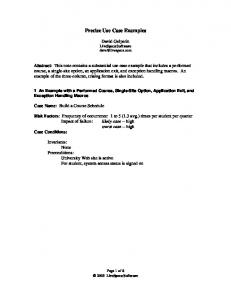
University Web Site. ENTER. 1. requests âCreate a Scheduleâ. 2. If (For student, a schedule already exists 23%) displays existing schedule. Else displays new ...
Coexistence simulations using the ITU-R path loss model P.452-15 and the database design taking into account practical parameters and findings from.
Delivering Efficient IT Services in the Digital Workplace. IT service management ... To reduce incorrect ticket assignme
Sep 24, 2012 - âRequirement Analysis for Power of 10â of the GEN6 project with the ... ICT sector, such as smart metering, meter data management, etc.
Cost models like COCOMO and sizing methods like Function Point Analysis (FPA) are ... The use case points method is a so
Delivering Efficient IT Services in the Digital Workplace. IT service management ... To reduce incorrect ticket assignme
Advanced analytics will change the landscape of ... As a big data software company, Splunk offers a very strong SIEM for
To start working with GPlates load the files from your Data Bundle for. Beginners: - Click on the .... can download thes
The Use Case Model describes the proposed functionality of the new system. ...
sequence diagram typically represents a single Use Case 'scenario' or flow of ...
The Use Case Model The Use Case Model describes the proposed functionality of the new system. A Use Case represents a discrete unit of interaction between a user (human or machine) and the system. A Use Case is a single unit of meaningful work; for example login to system, register with system and create order are all Use Cases. Each Use Case has a description which describes the functionality that will be built in the proposed system. A Use Case may 'include' another Use Case's functionality or 'extend' another Use Case with its own behaviour. Use Cases are typically related to 'actors'. An actor is a human or machine entity that interacts with the system to perform meaningful work.
A Use Case description will generally include: 1. General comments and notes describing the use case; 2. Requirements - Things that the use case must allow the user to do, such as , & etc. 3. Constraints- Rules about what can and can't be done. Includes i) pre-conditions that must be true before the use case is run -e.g. must precede ; ii) post-conditions that must be true once the use case is run e.g. ; iii) invariants: these are always true - e.g. an order must always have a customer number 4. Scenarios - Sequential descriptions of the steps taken to carry out the use case. May include multiple scenarios, to cater for exceptional circumstances and alternate processing paths; 5. Scenario diagrams -Sequence diagrams to depict the workflow - similar to (4) but graphically portrayed. 6. Additional attributes such as implementation phase, version number, complexity rating, stereotype and status
Actors
An Actor is a user of the system. This includes both human users and other computer systems. An Actor uses a Use Case to perform some piece of work which is of value to the business. The set of Use Cases an actor has access to defines their overall role in the system and the scope of their action.
Constraints, Requirements and Scenarios The formal specification of a Use Case includes: 1. Requirements. These are the formal functional requirements that a Use Case must provide to the end user. They correspond to the functional specifications found in structured methodologies. A requirement is a contract that the Use Case will perform some action or provide some value to the system. 2. Constraints. These are the formal rules and limitations that a Use Case operates under, and includes pre- postand invariant conditions. A pre-condition specifies what must have already occurred or be in place before the Use Case may start. A post-condition documents what will be true once the Use Case is complete. An invariant specifies what will be true throughout the time the Use Case operates. 3. Scenarios. Scenarios are formal descriptions of the flow of events that occurs during a Use Case instance. These are usually described in text and correspond to a textual representation of the Sequence Diagram.
Includes and Extends relationships between Use Cases One Use Case may include the functionality of another as part of its normal processing. Generally, it is assumed that the included Use Case will be called every time the basic path is run. An example may be to list a set of customer orders to choose from before modifying a selected order - in this case the Use Case may be included every time the Use Case is run. A Use Case may be included by one or more Use Cases, so it helps to reduce duplication of functionality by factoring out common behaviour into Use Cases that are re-used many times. One Use Case may extend the behaviour of another - typically when exceptional circumstances are encountered. For example, if before modifying a particular type of customer order, a user must get approval from some higher authority, then the Use Case may optionally extend the regular Use Case.
Sequence Diagrams UML provides a graphical means of depicting object interactions over time in Sequence Diagrams. These typically show a user or actor, and the objects and components they interact with in the execution of a use case. One sequence diagram typically represents a single Use Case 'scenario' or flow of events. Sequence diagrams are an excellent way to document usage scenarios and to both capture required objects early in analysis and to verify object usage later in design. Sequence diagrams show the flow of messages from one object to another, and as such correspond to the methods and events supported by a class/object. The diagram illustrated below shows an example of a sequence diagram, with the user or actor on the left initiating a flow of events and messages that correspond to the Use Case scenario. The messages that pass between objects will become class operations in the final model.
Implementation Diagram A Use Case is a formal description of functionality the system will have when constructed. An implementation diagram is typically associated with a Use Case to document what design elements (eg. components and classes) will implement the Use Case functionality in the new system. This provides a high level of traceability for the system designer, the customer and the team that will actually build the system. The list of Use Cases that a component or class is linked to documents the minimum functionality that must be implemented by the component.
The example above shows that the Use Case "Login" implements the formal requirement "1.01 Log on to the website". It also states that the Business Logic component and ASP Pages component implement some or all of the Login functionality. A further refinement is to show the Login screen (a web page) as implementing the Login interface. These implementation or realisation links define the traceability from the formal requirements, through Use Cases on to Components and Screens.