Three Switching Algorithms for a Fuzzy Direct Torque Control of Induction Motor Fed by a PWM Inverter F. Kadri Department of Electronics, University of Ouargla, Algeria
[email protected]
INTRODUCTION
SIMULATION RESULTS
In this work, we developed a strategy of intelligent control based on fuzzy logic for the control of an induction motor. The proposed control consists of an estimation of stator flux vector and electromagnetic torque, a fuzzy controller, and regulation based on the theory of direct torque control DTC. The originality of our work is the implementation of different switching topologies in different controllers by fuzzy rules that describe each algorithm. In this work, we will exploit the simplicity of implementation and robustness offered by fuzzy logic
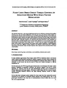
In practice, there are two important factors that affect the performance of the DTC: the error bands, and sampling frequency. Concerning the error bands, the practice has shown that the choice to 4% of the nominal values gives the best operating range. System Response in Start-Up State It shows the system start-up stabilization. In order to observe its dynamic behavior under transient state, until it reaches its steady state (Fs =0.75 Wb.T., Ts =10N.m.). We perform a zoom operation on the displayed signals “Fig. 3”. Steady Performance of the System To evaluate the efficiency of control system for the two controllers (according to both approaches), three tests are performed as follow: ¾Test of robustness for variation of torque. "Fig. 4" ¾Test of robustness for variation of flux. "Fig. 5" ¾Decoupling test of robustness for an inversion of torque and flux variation. "Fig. 6"
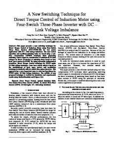
DEVELOPMENT OF DIFFERENT SWITCHING ALGORITHMS We propose the development of fuzzy controllers for three switching algorithms. With Hysteresis Controllers: (Algorithm one) In this technique in order to define the inverter switching pattern using flux and torque errors, two hysteresis controllers are used. it requires knowledge the flux and torque error and the history of this error "Fig. 1,a ". The set of fuzzy rules describing the operating principle of this algorithm is summarized by inference rules in equations 1, and 2.
Flux statorique Fs dans le repère d,q (algorithme 1)
Couple statorique Ts (algorithme 1)
Flux statorique Fs dans le repère d,q (algorithme 2)
0.8
Flux statorique Fs dans le repère d,q (algorithme 3)
Couple statorique Ts (algorithme 2)
Couple statorique Ts (algorithme 3)
0.8 14 14
0.6
12
0.6
12 0.4
0.6
10
0.4
12
0.4
10
0.2
8
0
6 4
-0.2
-4 -0.2
0 0.2 Fsd(Wb.T)
0.4
0.6
0.8
0
0.2
tension entre phase a et phase b (algorithme 1)
0.4
0.6
0.8
1
1.2
-0.2 0 0.2 Fsd(Wb.T)
courant de la phase a (algorithme 1)
tension entre phase a et phase b (algorithme 2)
-0.8
-0.6
-0.4
0.4
0.6
0.8
300
0.2
-0.2 0 0.2 Fsd(Wb.T)
courant de la phase a (algorithme 2)
tension entre phase a et phase b (algorithme 3)
0.6
0.8
1
1.2
5 i1 (A )
Va b( V)
i1 (A ) 1
1.01
1.02
1.03
1.04 t(s)
1.05
1.06
1.07
0.6
0.8
0
0
-5
1.1
1.15
1.2 t(s)
1.25
1.3
Flux statorique Fs
1
1.2
0 -5 -10
-400 -15
1.35
1.01
1.02
1.03
1.04 t(s)
1.05
1.06
1.07
1.08
-500 1
1.05
1.1
1.15
1.2 t(s)
1.25
1.3
1.35
1
1.02
1.04
1.06
1.08
1.1
Couple statorique Ts
Flux statorique Fs
1
1.05
1.1
1.15
t(s)
(b) Fig. 3: System response in start-up state . (a) algorithm 1, (b) algorithm 2, (c) algorithm 3.
¾Algorithm 2 : (Four-Band Flux Controller and Five-Band Torque Controller). ¾Algorithm 3 : (Dual-band Flux Controller and Three-Band Torque Controller).
0.8
5
0 -100
-300
-15
-400 1.05
0.6 t(s)
-200
-10 -300
1
0.4
courant de la phase a (algorithme 3)
100
0
-100
(a)
0.2
15 10
-200
-15
0.4
300
100 0
-5
-10
-400
-0.4
200
5 100 0
-0.6
10
-200 -300
-0.8
400
15
200
-100
-2
-0.8 -1
t(s)
0.4
300
10
200
Va b( V)
2
0
400
400
4
0 -0.6
-2
-0.8 -1
t(s)
i1 (A )
-0.4
Va b( V)
With Error-Band Controllers (Algorithm 2, and 3) in this technique "Fig. 1,b", history of the flux and torque error does not play any role in the switching pattern for the inverter this technique can be classified based on the number of the error levels. We propose two algorithms whose operating principle is presented by inference rules in equations 3, 4, 5, and 6.
-0.6
-0.2
0 -0.6
-2
-0.8 -0.8
6
-0.4
-0.4
0
-0.6
0
2
2 -0.4
T s (Nm)
4
-0.2
8
0.2
F s q( W b.T )
6
T s (Nm)
0
F s q( W b.T )
8 T s (Nm)
F s q( W b.T )
10 0.2
Couple statorique Ts
1.2 t(s)
1.25
1.3
1.35
(c)
Flux statorique Fs
Couple statorique Ts 20
0.78
0.76
15
0.74
5
0.66
10
0.7 0.68
5
0.66
0.64
0
0.1 t(s)
0.15
0.2
0.02 0.04 0.06 0.08
0.1 t(s)
0.12 0.14 0.16 0.18
0.2
0.68
0
0.05
0.1 t(s)
0.15
0.2
0
0.02 0.04 0.06 0.08
0.1 t(s)
0.6
0.12 0.14 0.16 0.18
0
-5 0
0.02 0.04 0.06 0.08
15
15
10
10
10
5
0
-5
-10
-15
-15
-15
0.15
0.2
0.1 t(s)
0.12 0.14 0.16 0.18
0.2
0
-5
-10
0.1 t(s)
0.02 0.04 0.06 0.08
5 i1(A)
i1(A)
i1(A)
5
-5
-10
0.05
0.12 0.14 0.16 0.18
courant de la phase a
15
0
0.1 t(s)
courant de la phase a
courant de la phase a
0
5
0.62 -5
0.05
10
0.7
0.64
0.62
0.6 0
0.72
0.66
0.64
0
0.62
15
0.74
0.72
F s(W b .T )
0.68
F s( W b .T )
10
0.7
T s (Nm)
0.72 T s (Nm)
F s( W b .T )
0.78
0.76
15
0.74
T s (Nm)
0.78 0.76
0
0.05
0.1 t(s)
0.15
0.2
0
0.05
0.1 t(s)
0.15
0.2
(a) (b) (c) Fig. 4: System response in steady state for variation of torque (15 → 5) N.m. (a) algorithm 1, (b) algorithm 2, (c) algorithm 3. Flux statorique Fs
Couple statorique Ts
Flux statorique Fs
Couple statorique Ts
Flux statorique Fs
0.8 0.75
0
0.6
0.1 t(s)
0.15
0.2
and d ΔT / dt N
ΔT SN and d ΔT / dt P
0.05
0.1 t(s)
0.15
Then Then
K T = 1. K T = −1 .
ΔT SN and d ΔT / dt N Then
K T = 0.
ΔT BN
K T = −1 .
Then
⎧ if ⎪ ⎪ if ⎨ ⎪ if ⎪ if ⎩
(1)
Δ φ BP Δφ Z Δφ Z
dΔ φ /dt
and
Then K φ = 0 .
P N
Δ φ BN
(2)
Then K φ = 1 .
0.1 t(s)
0.12 0.14 0.16 0.18
0.2
0.45 0
0
-5
-10
-15
-15
-15
0.15
0.2
⎧ if ⎪ ⎨ if ⎪ ⎩ if
0
0.05
0.1 t(s)
0.15
0.2
0.02
= 2.
K T
= 3.
ΔT
ΔT ΔT ΔT
MN
Then
BN
Then
BP
K T
Then
K T = 1.
Z
Then
K T = 0.
BN
Then
K T = −1.
Z
BP
-εT 0 εT
-1
= 4.
N
P -εφ 0 εφ
Δφ
(a)
Δ φ
SP
Then K
if
Δ φ
SN
Then K
if
Δ φ
BN
Then
MN SN SP
-(ε1T+ε1T) -ε1T
BN
1 -1
⎧⎪ if ⎨ ⎪⎩ if
(5)
BN
1 -1
ΔT
if
K φ
= 0 .
Couple statorique Ts
φ
= 1.
φ
= 2.
K φ
= 3 .
0.75
10
0.7
5
0.65
0
0.6 0.55
(4)
Flux statorique Fs
-εφ
ε1T
0
ΔT
SN
SP
0
Δφ
BP
Couple statorique Ts
εφ
0.12 0.14 0.16 0.18
0
0.6
Δφ
P
Then
K
φ
= 1.
N
Then
K
φ
= 0.
BN SN SP BP
BN
1 -1
-εT
0
ΔT
Z
εT
0
0.05
0.1 t(s)
0.15
0.2
1 -1
BP
1 -1
Δφ
0.1 t(s)
0.12
0.2
0.14
0.16
0.18
0.2
0
0.1 t(s)
0.15
0.2
0
0.6
0.5
0.02 0.04 0.06 0.08
0.1 t(s)
0.12 0.14 0.16 0.18
-5 -10
0.55
-20 0.05
5
-15 -20
0.45 0
0.05
0.1 t(s)
0.15
0.2
0.02 0.04 0.06 0.08
0.1 t(s)
0.12 0.14 0.16 0.18
0.2
courant de la phase a
10
5
5
0
0
-5
-5
-10
-10
-10
-15 0.04
0.06
0.08
0.1 t(s)
0.12
0.14
0.16
0.18
0.02
0.04
0.06
0.08
0.1 t(s)
0.12
0.14
0.16
0.18
0.2
0.02
0.04
0.06
0.08
0.1 t(s)
0.12
0.14
0.16
0.18
(a) (b) (c) Fig. 6: Response for a decoupling test (torque: 10 → -10 N.m., flux: 0.75 →0.5 Wb.T.) (a) algorithm 1, (b) algorithm 2, (c) algorithm 3.
CONCLUSION 1
P
0
Couple statorique Ts
10
0.7
courant de la phase a
0
0.02
d(Δφ)/dt
(c)
0.08
0.65
-5
P
N
0.06
0.75
10
-15
(6)
-5
-15
0.45 0
10
d(ΔT)/t
-εφ 0 εφ
(b) Fig. 2: . Fuzzification of inputs (a) Algorithm 3 , (b) Algorithm 2, (c) Algorithm 1
N
0.04
Flux statorique Fs
-10
0.5
-20 0.1 t(s)
5
0.55
-15
0.02 0.04 0.06 0.08
10
0.7 0.65
courant de la phase a
Δφ
0.12 0.14 0.16 0.18
0.8
0.75
5
1 -1
BP
-5 -10
0.5 0.45
i1(A)
ΔT
(3)
Then
F s( W b .T )
= 1.
K T
BP
i1(A)
K T
Then
Δ φ
T s (Nm)
Then
SN
if
F s( W b .T )
SP
ΔT
⎧ ⎪ ⎪ ⎨ ⎪ ⎪ ⎩
i1(A)
= 0.
ΔT
BN
-1
KT
T s (Nm)
Then
0.1 t(s)
(a) (b) (c) Fig. 5: System response in steady state for variation of flux (0.75 →0.5 Wb.T.) (a) algorithm 1, (b) algorithm 2, (c) algorithm 3.
Then K φ = 0 .
F s( W b .T )
BP
0.02 0.04 0.06 0.08
0
-5
-10
0.1 t(s)
-6
0.2
5
5
0
0.05
0.15
10
-5
0
0.1 t(s)
courant de la phase a
0.8
ΔT
0.05
-10
Flux statorique Fs
⎧ if ⎪ ⎪ if ⎪ ⎨ if ⎪ if ⎪ ⎪⎩ if
0
-4 0.02 0.04 0.06 0.08
10
5
Then K φ = 1 . dΔ φ /dt
and
2
-2
0.2
courant de la phase a
10
K T = 0.
4
0.5 -6
0.45 0
0.12 0.14 0.16 0.18
i1(A)
Then
0.6 0.55
-4 0.1 t(s)
T s (Nm)
ΔT SP
and d ΔT / dt P
K T = 1.
6
-2
0.02 0.04 0.06 0.08
i1(A)
ΔT SP
Then
8
0.65
0.5 -6 0.05
i1(A)
ΔT BP
2 0
0.55
-4 0
courant de la phase a
⎧if ⎪ ⎪if ⎪⎪if ⎨ ⎪if ⎪if ⎪ ⎪⎩if
4
T s (Nm)
2
6
-2 0.5 0.45
12 10
0.7
8
0.65
F s( W b .T )
4
T s (Nm)
0.6
F s( W b .T )
6 T s (Nm)
F s( W b .T )
0.7
8
0.55
14
0.75 10
10 0.7 0.65
Couple statorique Ts
0.8 12
12
0.75
(a) (b) Fig. 1: Induction motor fuzzy direct torque control block diagram (a) Algorithm 1 , (b) Algorithm 2, and3
1
In this work we describe mainly the implementation of a law of robust and effective fuzzy logic for three different switching algorithms. The originality of our work was to combine the simulation experiments of different algorithms for defining a control structure implementing the best ratio simplicity/performance given by algorithm three. We made a fuzzy logic strategy of switching without need of classical switching table. This opens the way to the development of several algorithms based on the second approach presented in this paper. Finally, we believe that the proposed solutions have improved performance and enhanced stability with the make use of robust fuzzy control.
Third International Conference on Electrical Engineering Design and Technologies (ICEEDT09)
Oct. 31- Nov. 2, 2009, Sousse, Tunisia