of color and depth images from top-view camera. The U- disparity as depth image projection is introduced in order to inc
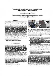
Top-view Based People Counting Using Mixture of Depth and Color Information Chonthisa Wateosot Faculty of Engineering, Princess of Naradhiwas University Narathiwat, Thailand, 96000 E-mail:
[email protected]
ABSTRACT People counting is very important for some applications, such as, surveillance, event organization, flow control application and etc. In this paper, we propose a novel technique for people counting using the mixture of color and depth images from top-view camera. The Udisparity as depth image projection is introduced in order to increase the accuracy of counting number. Our method can count accurately at 93% in real-time. KEY WORDS People counting, Color U-disparity, RGB-D image
1. Introduction People counting is an important technique that can be used in many applications, such as, tourists flow estimation, retail management, event organization, security application, marketing research pedestrian traffic management and etc. Actually, many researches are done in this field [1], mostly using the motion and color features through object tracking and counting. However, one of the most difficult problems is the people occlusions when considering it at the large entrance gates, such as, supper store, hall or building entrance. For example, a group of people working in the counting area at the same time being very close to each other can produce the partial occlusion. In this situation, only the motion and color properties cannot deal with the problem. However, we believe that the depth information with the corresponding color pattern give us the precious information to solve this problem with a minimum cost and better accuracy. In this paper, we propose a technique for people counting using the mixture of depth and color images from top-view camera. The key idea is that people will be detected and segmented from depth image instead of color image. And then, using both color and depth images in the tracking process. Based on this idea, the Color Udisparity, defined as an intermediate transformed image space, is applied for people segmentation and tracking. Then, the counting process is applied. We present our paper in four sections as the following: related work, our proposed system in detail, experimentation result, and conclusion respectively.
Nikom Suvonvorn Faculty of Engineering, Prince of Songkla University Hatyai, Songkhla, Thailand, 90112 E-mail:
[email protected]
2. Related work Many works has been done by researchers for the people counting method. Albiol et al [1] use the direction of people in the counting process. The gradient stack is applied for estimating the background. The direction of the optical flow is obtained from the horizontal projection of the gradient image. This method cannot count several people when there is an occlusion between them. Xi Zhao et al [2] count the number of people based on face detection, tracking and trajectory classification. The facetracking method combines a new scale invariant Kalman filter with kernel based tracking algorithm. The accuracy rate is up to 93%. The method does not work properly when the color of background is complex such as outdoor where the illumination changes drastically. Chih-Wen Su et al [3] studied the detection of people using the symmetry property of the human torso. The process can solve the problem of the incomplete extraction of the human silhouette. The accuracy of the result is 85%. Most of the missed detections were caused by the vertical occlusion. In this case, people who were occluded by the others only showed head and shoulders in the video frame. Jae-Won Kim et al [4] count the number of moving people entering the security door, which are detected and tracked using a fixed single camera. The object is detected using background subtraction, and then tracked. The bounding box allows partial object occlusion reducing the false warning. Tarek Yahiaoui et al [5] count the passengers in buses based on stereovision, segmentation, tracking and counting from original stereoscopic images, a dense disparity map which is converted into a height map. The height maps are segmented in order to highlight the passenger’s heads at different levels. The Kalman filtering is applied for tracking, and followed by the counting step. Our research is inspired form the work of Tarek that performs good results.
3. Proposed System In this section we introduce our proposed system for people-counting from the top view using depth and color images. Firstly, the depth images acquired from Kinect camera are analyzed for detecting moving objects using the background subtraction technique. Then, the heads of person are identified by object segmentation in the Udisparity representation. Next, the corresponding color
ROI of the heads is located from the color image of Kinect via camera calibration. The depth-color feature of the head is then tracked using the particle filtering method. And finally, the head tracking is used for the counting process. The overview of the proposed system is shown in the figure 1. IR Camera
(a) (b) Figure 2.the result of motion detection .
Motion Detection Blob Analysis
After motion detection, the blob analysis is applied in order to find the bounding box of the moving person. This bounding box contains certainly peoples, but the number is unknown, which makes necessary a segmentation step.
RGB Camera
Color Matching
People Segmentation Blob Analysis U-Disparity
3.2 People Segmentation In this step, each blob will be studied in detail in order to compute the exact number of people with its regions; one blob may be split into several blobs. To achieve this goal, we use the U-disparity representation as an intermediate transformed domain. U-disparity is estimated from disparity map on x-axe defined by the following equation:
People Tracking
People Counting Figure 1. Proposed System .
V ( I ) I u
3.1 Moving Object Detection In our system, the motion detection is used to segment the moving object in depth image using background subtraction technique. In our particular problem, the motion of people may occur in the full area of the observation view. By performing motion detection only on color image, we found that the result is inapplicable. In contrast, motion detection on depth image is more reliable than on color image, noted that the change of the illumination or motion has strong impact on the intensity of color image but not on the depth information. In our system, we apply the Gaussian Mixture Model (GMM) method [6] for background modeling. The background is modeled by computing its probability P( X t ) as the following: K
P( xt ) i ,t * ( xt , i ,t , i ,t )
(1)
i 1
where
i ,t
is weighted Gaussian, K is number of
Gaussian (fixed to 5), And
is probability of Gaussian
function defined by: ( X t , , )
1
1 n 2
1
(2 ) 2
e 2 ( X t t )T 1 ( X t t )
(2)
The result of background subtraction is shown in figure 2. We can notice that motion object can be well segmented in the most cases that separate moving person from the floor.
(3)
where
I u is u-disparity, and V is a vertical accumulate operator of similar intensity on each column of disparity map. Figure 3 shows results of u-disparity for the moving object of one blob. From the results, we can notice that the u-disparity can discriminate the upper structure of human in the occlusion motions by its depth information from the top-view.
(a)
(b) Figure 3. the U-Disparity
In each blob, by using this u-disparity the head positions are marked by selecting the local maximums of depth values. Then, their sizes are considered in order to verify the real number of person. And the blob is split into the corresponding number. Finally, the color from color image is then matched to each blob. Colors can represent the parts of body depending on hair or cloth colors, which is necessary for the tracking process. This step is done by segmenting the moving person in color image that correspond to the person found in the depth image via image transformation, using camera calibration matrix. Firstly, the depth pixels will be transformed into 3D points P3D.x, P3D.y, P3D.z using the following equations: P3D.x ( xd cxd )
(depth( xd , yd )) fxd
(4)
P3D. y ( yd cyd )
(depth( xd , yd )) fyd
(5)
P3D.z depth( xd , yd )
(6)
Where fxd , fyd , cxd , cyd are intrinsic of IR camera fxd =5.9421434211923247e+02
distance to the predicted blob. The process will be repeated until finding the optimal one. The linear stochastic differential equation of Kalman filter is defined by the following:
fyd =5.9104053696870778e+02
xk Axk 1 Buk 1 wk 1
cxd =3.3930780975300314e+02
x 1 y 0 vx 0 v y 0 k ,i
cyd =2.4273913761751615e+02 Then, the 3D points are converted to 2D points in color image. P3D '.x P3D.x P3D '. y R. P3D. y T P3D '.z P3D.z
P 2 Drgb .x P 2 Drgb . y
P3D '.x * fxrgb P3D '.z P3D '. y * fyrgb P3D '.z
(7)
Where
CX rgb
(8)
CYrgb
(9)
where R and T are the rotation and translation matrix respectively. 9.9984628826577e 01 1.2635359098409e 03 1.7487233004433e 02 R 1.4779096108364e 03 9.9992385683545e 01 1.2251380107635e 02 1.7470421412464e 02 1.2275341476520e 02 9.9977202419948e 01 1.9985242312092e 02 T 7.4423738761613e 04 1.0916736334322e 02
fxrgb
=5.2921508098293293e+02
fyrgb =5.2556393630057437e+02
cxrgb =3.2894272028759258e+02 cyrgb
=2.6748068171871557e+02
Finally, the transformed depth pixels, figure 4(b), and color pixels, figure 4(a), is matched with a simple and operator, which produces the result shown in figure 4(c).
0 t 1
0
0 0
1 0
velocity of blob in the kth frame respectively. Here, we assume that the motion of blob between two successive frames can be uniformly approximated as straight line; the frame interval Δt is very short. For the measurement, zk is defined as the detected blob in frame (k+1) th that is
zk Hxk vk
(12)
The random variables wk and vk represent Gaussian noise of the process and measurement respectively. The algorithm of Kalman filter estimates a process by using feedback control technique: estimating the process state by an appropriate model and doing feedback by noisy measurements. As such, the equations of Kalman filter are formed into two groups: prediction and correction equations. In the post tracking of hand, the algorithm can be described as the following figure 5. Prediction xˆ k
3.3 People Tracking From the last section, in each frame, the moving persons are segmented as blobs with it properties, such as, centroid, and color pattern. In our tracking method, we combine two techniques for a better real time tracking. Firstly, the Kalman filter is applied for predicting the movement of the person in frame i+1 using centroids of the previous frames. Secondly, the nearest blob to the predicted one of the frame i+1 is selected, and then compared to the current blob of the frame i with its similarity using normalized color pattern correlation. If its similarity is acceptable comparing to a threshold, we believe that the selected blob is the right tracking person. If not, the other blob will be selected ordering it by its
(11)
xk (x, y, vx, vy) are the centroid and the
1) Estimate the next state
(a) (b) (c) Figure 4. (a) color image (b) depth image (c) color object
0 x t y wk 1,i 0 vx 1 v y k 1,i
(10)
Correction 1) Compute the Kalman gain K k Pk H T ( HPk H T R) 1
Axˆ k 1 Buk 1
2) Estimate the error covariance of next state
2) Correct with measurement zk xˆ k xˆ k1 K k ( z k Huk 1 xˆ k )
Pk APk 1 A1 Q
3) Update the error covariance Pk ( I K k H ) Pk
Initial estimates for xˆ k 1 and
Pk 1
Figure 5. The operation of Kalman filter.
3.4 People Counting In this section, we explain how to count the tracking people. The figure 6 shows the counting state machine. Firstly, all blobs in the field of view will be tracked using the method explained above. Each blob will have three statuses: alive, counted, and dead. Alive status is distributed to the blob when its presence on the scene is greater than a threshold th1. Counted status is defined for the blob when its presence on the counting area is greater than a threshold th2. And the dead blob is when people go out from the field of view.
time _ scene th1
In our experimentation, the table 1 shows the correction rate with respect to the number of people in the testing cases.
Start
Alive
Stop
Comm and
time _ scene th1 Counted
time _ dead th3 Dead
2 Click Lefttime _ count th time _ count th 2
time _ dead th3
Figure 6. Counting finite state machine.
4. Experimental results The dataset is acquired from Kinect camera installed on the top of the main entrance of the Faculty of Engineering, Prince of Songkla University. The color and depth image is analyzed at the same time via RGB camera and IR camera, shown in figures 7. The dataset is done using our adaptive version of CL NUI Platform with resolution 320*240 pixels. People walk through the counting area, setup horizontally at the middle of the field of view. Four groups (1 person, 2 persons, 3 persons, 4 persons respectively) are testing with two directions (in and out). Testing system is run on Intel processor Dual Core, 2.4 GHz, 1 GB memory.
(a)
(b)
Groups
Time
Persons
Detected
Correct rate
1 person
20
20
20
100.00
2 persons
10
20
19
95.00
3 persons
6
18
16
88.89
4 persons
4
16
14
87.50
Cases
Time
Persons
Detected
Correct rate
In
20
37
35
94.59
Out
20
37
34
91.89
Average
40
74
69
93.24
Table1: the correction rate of our counting system
We can note that globally our system can perform very good correction rate in most of the cases at around 93%. However, the system cannot count correctly when the heads of two persons are connected physically. Additionally, when two persons have mostly the same height, our system cannot well identify them.
5. Conclusion In this paper, we presented a people counting system from the top-view images using depth and color information. The U-disparity is specially applied for segmenting the occluded people, which is tracked by a mixture of position and color properties. The system provides a good recognition rate at 93.0%. In the future, some additional techniques for head segmentation could be applied for increasing the accuracy of the system.
References
(c)
(d)
(e)
(f)
(g) (h) Figure 7. Testing dataset (a) (b) 1 person, (c) (d) 2 persons, (e)(f) 3 persons, (g)(h) 4 persons.
[1] Antonio Albiol, Inmaculada Mora, and Valery Naranjo, “Real-Time High Density People Counter Using Morphological Tools”, IEEE Transactions on Intelligent Transportation Systems, Barcelona, VOL. 2, NO. 4, pp. 204-218, Dec 2001. [2] Xi Zhao, Emmanuel Dellandrea and Liming Chen, “A People Counting System based on Face Detection and Tracking in a Video” , Sixth IEEE International Conference on Advanced Video and Signal Based Surveillance, Genova, pp.67-72, 2-4 Sept 2009. [3] Chih-Wen Su, Hong-Yuan Mark Liao and Hsiao-Rong Tyan, “A Vision-based People Counting Approach Based on the Symmetry Measure”, IEEE International Symposium on Circuits and Systems, Taipei, pp. 2617-2620, 24-27 May 2009. [4] Jae-Won Kim, Kang-Sun Choi, Byeong-Doo Choi, and Sung-Jea Ko, “Real-time Vision-based People Counting System for the Security Door”, ITC-CSCC :International Technical Conference on Circuits Systems, Computers and Communications, Korea, pp. 1418-1421, 2002 [5] Tarek Yahiaoui, Cyril Meurie, Louahdi Khoudour, and Francois Cabestaing , “A People Counting System Based on Dense and Close Stereovision”, Image and Signal Processing: 3rd International Conference, ICISP 2008, France, pp.59-66, 2008