Multimedia Information NEtwork (MINE) Lab. Department of Computer Science and Information Engineering. Tamkang University. Tamsui, Taiwan. R.O.C..
Toward a Generic Spatial/Temporal Computation Model for Multimedia Presentations Timothy K. Shih and Anthony Y. Chang Multimedia Information NEtwork (MINE) Lab Department of Computer Science and Information Engineering Tamkang University Tamsui, Taiwan
R.O.C. email: TSHIHQCS .TKU .EDU .TW
Abstract Relations among temporal intervals can be used to assist the automatic generation o f multimedia presentations. In this paper, we analyze the domains o f interval temporal relations. A set o f algorithms is proposed to derive reasonable relations between intervals. Possible conflicts in the user specification are firstly detected and eliminated. Our mechanism then constructs partial order relations among temporal intervals before the presentation time chart is built. The algorithm is extended for objects in an arbitrary ndimensional space. Thus, presentation layouts in 2-D space, or Virtual Reality object representations in 3-D space can be constructed. We use our algorithms to design a reasoning system that generates the schedule and layout o f multimedia presentations.
Key words: Temporal Interval Relations, Multimedia Presentations, Spatial/Temporal Model
1
Introduction
Multimedia applications usually contains a number of multimedia resources to be presented sequentially or concurrently. Temporal interval relations among resources are provided by the users. These resources need to be analyzed to ensure that there is no conflict among resources. Moreover, some of these resources, such as video clips or animations, occupy screen space. The spatial relations among resources need to be computed and represented in the multimedia program. The work discussed in [l] only states temporal interval relations. We found that these relations can be generalized for spatial modeling. The contributions of our paper are to give a complete discussion of different possible domains of interval relations based on graph representations. A set of
0-8186-7819497 $10.00 0 1997 IEEE
algorithms are developed to derive multimedia presentation schedules and layouts from user specifications. Possible conflicts of user specifications are eliminated. Most importantly, we extend the algorithms to compute relations among objects in an arbitrary n-dimensional space. Section 2 discusses the relation domains and their properties. In section 3, algorithms are presented. The extension of these algorithms are given in section 4. Issues of realizing an automatic system is given in section 5. And finally, our conclusions are given in section 6.
2
The Relation Domains
According to the interval temporal relations introduced in [l],there exists thirteen binary relations between two temporal intervals. These relations were used in many spatial/temporal computation researches [2] of multimedia applications, including the one we proposed [3]. Allen’s work discussed in [I] includes a table showing the composition of interval temporal relations. Based on the table, we propose two algorithms in this paper, using the directed graph, for interval relation compcsitions. These algorithms can be used to compute the binary relation between an arbitrary pair of intervals. In sections 4, we extend our algorithms for objects in an arbitrary n-dimensional space. The composition of interval temporal relations may result in an unknown derivation. For instance, if “X before Y” and “Y after Z”, there is no information that can be derived between X and Z. On the other hand, the composition may result in a multiple derivation. For example, if “X before Y” and “Y during Z’,the composed relation for X and Z could be “before”, “overlaps”, (‘meets”, “during” , or “starts”. These derived relations are called reasonable relations in our discussion. A reasonable set is a set of reasonable relations
228
Authorized licensed use limited to: Tamkang University. Downloaded on March 28,2010 at 22:39:24 EDT from IEEE Xplore. Restrictions apply.
according to our definition. A reasonable set can not be empty, since there must exist at least one relation between any two intervals, assuming that they are in the same one dimensional space (i.e., the time line). However, a reasonable set may contain all 13 relations, which also denote that there is no information can be derived. In the multimedia presentation scheduling system we proposed [3], the temporal relations of multimedia objects are provided by the user. In some cases, relation compositions may result in a conffict derivation due to the user specification. However, we did not consider this case in [3]. For example, if specifications “X before Y” , “Y before Z” , and “X after Z” are declared by the user, there exists a conflict between X and Z. We can not tell whether it is “X after Z” or “X before Z”. The new algorithms we propose in this paper overcome our previous strategy. The new presentation scheduling system is able to issue an error message showing the conflict and suggest the user to choose a correct relation. We analyze the domain of interval temporal relations and use an directed graph to compute the relations of multimedia objects. In the computation, we consider all possibilities: the unknown derivations, the multiple derivations, and the conflict derivations. Some terms used in the graph are defined as the following:
there is no conflict, the two domains are equal. The reduced relation domain contains relations specified by the user only. It is possible that the user issues a conflict situation. To avoid the occurrence of conflicts, we place a restriction on the user’s interaction. Instead of allowing the user to add an arbitrary relation to the relation graph, we only allow the user to add objects to a restricted relation domain, which is a tree and a subdomain of the reduced relation domain. That is, when the user is about to add a new edge, the user either adds a new node connected to an existing node via an user edge, or joins two sub-trees via the user edge. No cycle is created in the restricted relation domain. Thus, the conflict situation does not exist. When deleting an user edge, the user has to maintain the connectivity of the tree. If all nodes are connected, the user specification is complete. Otherwise, the presentation system should alert the user to complete the specification. The above domains can be summarized as the following: The complete relation domain (a complete graph): contains user edges and derived edges, with possible cycles and possible conflicts. The reasonable relation domain (a graph): contains user edges and derived edges, with possible cycles but no conflict. The reduced relation domain (a graph): contains only user edges, with possible cycles and possible conflicts. The restricted relation domain (a tree): contains only user edges, without cycle.
Definition: An user edge denotes a relation between a pair of objects defined by the user. The relation may be reasonable or non-reasonable. Definition: A derived edge holds a non-empty set of reasonable relations derived by our algorithm. The relation of the two objects connected by the derived edge can be any reasonable relation in the set.
The four domains are used in the analysis and computation of object relations. In the next section, we propose two algorithms computing the reasonable relation domain.
For each pair of objects in the time line, there exists a set of possible binary relations held between the pair of objects. For an arbitrary number of objects (denoted
3
by nodes), some of the relations (denoted by edges) are specified by the user while others are derived. If there exists a cycle in the directed relation graph, a conflict derivation may occur. However, if there exists no cycle, there is no conflict. There may exist an unknown derivation which represents that there is no enough information to derive a relation between a pair of objects. Based on the above considerations, we suggest that the computation domain reveals four types, as discussed below. The complete relation domain is a complete graph which contains possible conflicts. We want to find a reasonable relation domain containing no conflict derivation. Note that, in these two domains (i.e., the complete and the reasonable), both user edges and derived edges exist. If there is a conflict among a set of user edges, one of the user edge must be removed from the cycle, or the relation of that user edge must be re-assigned. If
Generating Presentation
This section discusses a serial of algorithms to generate multimedia presentations from user specifications. Firstly, we discuss two algorithms for computing the reasonable relation domain, which contains no conflict and thus can be used for generating schedule or layout of a presentation. Next, a representation of partial order relation is used to denote the topological order of objects. An algorithm takes as input a reasonable relation domain and generates these partial order sets (POSets) is presented. Another algorithm generates schedule and layout from the POSets is also given.
3.1
Computing Reasonable Relations
The first algorithm computes the reasonable relation domain from the reduced relation domain. User edge
229
Authorized licensed use limited to: Tamkang University. Downloaded on March 28,2010 at 22:39:24 EDT from IEEE Xplore. Restrictions apply.
.I
In ComputeRD1, we use the conflict elimination algorithm. A conflict occurs only if there is a cycle. For each cycle in the reduced relation domain, the ElimznateConflicts algorithm finds a derived edge between any two consecutive edges, namely, ( n ,, n,+l) and ( n t + l rn,+2). The algorithm then checks if the last user edge making the cycle represents a relation (i.e., (nk,nk-l).r) belongs to the reasonable set computed for the user edge (i.e., m).If not so, the algorithm asks the user to choose an arbitrary relation r' belongs to the reasonable set and use the relation to replace the original one.
conflicts are eliminated and derived edges and cycles without conflict are added. The second increases user edges one by one in a restricted domain, aild the corresponding derived edges are added to the reasonable relation domain. The resulting domain may have cycles due to the insertion of derived edges. But no conflict occurs. The DurDose of the first alrrorithm is to add derived edges to the reduced relation domain. If there is a conflict cycle in the original reduced relation dcmain, the algorithm eliminates that conflict first by alerting the user to select a reasonable relation. Thus, the resulting reasonable relation domain is a complete graph, which is equal to the complete relation domain. This conflict elimination is achieved by invoking the ElimznateConfEicts algorithm. Suppose G is a graph of the reduced relation domain, and GV and GE are the vertex set and edge set of G, respectively. Initially the reasonable relation domain is set to the reduced relation domain. The algorithm computes derived edges based on user edges. The reason of using the user edges is that these edges contain the minimal arid sufficient inforniation of what the user wants. If the algorithm computes derived edges from other derived edges. eventually, the algorithm has to compute the set intersection of all possible derivations for the reasonable set of the new derived edge. The algorithm starts from taking each path of user edges of length 2, and computes a derived edge from that path. The insertion of edge e = ( a , b ) results a cycle, but no conflict. The reasonable set of edge e (i.e., e.rs) is computed from two edges, ( U , nk-l) and ( n k - 1 , b ) , which are user edges or derived edges. Since we increase the path length, p l , of the path of user edges one by one. the derived edge ( a , nk- (or user edge; if p l = 2) must have been computed in a previous iteration. The algorithm repeats until all edges are added to the complete graph Kn , which contains n * ( n - 1)/2 edges. The first algorithm, CompuieRDl, is given below: v
.
I
-
Algorithm : EliminateConjlicts Input: G = ( G V ,GE) Output : G' = (G' V , G'E) Preconditions : G contains only user edges A G' = G Postconditions : G' = G , but the reasonable sets of edges in G' may be changed Steps : 1 : for each P = ( ( n l , n2),(n2, ns), ..., (nk-l, nk)) in G', with nl = nk A k > 3 1.1:foreach i , l < i L k - 2 1.1.1 : set (nz,n,+2).rs = RelComp((n,, nz+l).rs, (n,+~,n ~ + 2 ) . ~ 3 ) 1.2 : rs = RelComp((nk,nk-2).rs1 (nk-2, nk-l).rs) 1.3 : i f (nk, n k - l ) . r rs then 1.3.1 : ask user to choose an r' E rs 1.3.2 : set ( n k , nk-l).r = r'
Algorithm : C o m p u t e R D l Input : G = ( G V , G E ) Output : Ii'n = ( K n V , K n E ) Preconditions : true Postconditions : GV = Kn V A G E 5 Kn E Steps : 1 : G = EliminoteConflicts( G ) 2:Kn = G ~ p l = 2 3 : repeat until I Kn E I = I Zin V I * (I Zi', V I -1) / 2 3.1:foreach e = ( a , b ) A e 4 K n E A a E K n V A b E Kn Vsuch that there is a path of user edges from a to b , with path length = p l 3.2 : suppose ( ( n l , n z ) , (n2, n3), ...,( nk--l, nk)) is a path with a = nl A b = nk A k = p l + 1 3.3 : s e t e.rs = R e l C o m p ( ( a , nt.l).rs,(nk-l, b ) . r s ) 3.4:IinE=KnEU{ e } 3.5 : p l = p l + 1
In function RelComp, the reasonable set computed must be the union of all possible combinations of the pair of relations obtained from the two input reasonable sets, namely, m 1 and 7 3 2 . The function uses a table lookup function to obtain a set of reasonable relations. The TubleLookUp function (definition omitted) uses the relation composition table discussed in [l],if the algorithm is to compute relations of objects in a 1-D space. We have another table for objects in a 2-D space discussed in section 4. However, it is the same algorithm to compute the reasonable relation domain. Only the amount and type of relations are changed (i.e., changes from 1-D relations to 2-D relations). The following is the function computes a reasonable set: Algorithm : RelComp , Input : r s ~rs2 Output : rs Precondtttons : true Postconditions : true Steps : 1 : r s = U V rl E rsl , V rz E rs2 e( r l ,rz)E rs1 x rs2 TubleLookUp(r-1, r2)
In the actual implementation of a multimedia presentation system, depending on the user's specification,
230
Authorized licensed use limited to: Tamkang University. Downloaded on March 28,2010 at 22:39:24 EDT from IEEE Xplore. Restrictions apply.
directions of user edges are easily decided and represented in the implementation. The first algorithm assumes that a set of relations is provided by the user. However, in an interactive system, the user may incrementally adds user edges. The set of relations is unknown before the completion of the multimedia specification. In the next algorithm, we allow the user edges to be added to the graph one by one. Thus, our algorithm is more realistic for a system of interactive multimedia presentation designs. The restricted relation domain is a tree. The reason for using a tree is to avoid cycles which may introduce conflicts. A multimedia presentation contains a number of objects. When a new object is added t o the presentation, an user edge and a node representing the new object is added. A number of derived edges are also inserted. Adding a new node to the complete graph Kn requires adding n new edges, where n is the number of nodes, to complete Kn+l. Since a complete graph is strongly connected, there exists an edge between each pair of nodes. When a new user edge is added, we can compute other derived edges from checking the composed relations between an existing edge and this new user edge. Algorithm AddUL adds an user edge 1 = ( a , b ) to a complete graph h‘n: Algorithm : AddUL Input : I = ( a , b ) , Kn = (Kn V , Kn E ) Output : Kn+i = (Kn+i V , Kn+i E ) Preconditions : I 4 Kn E A a E Kn V A b 6 Iin V Postconditions:I Kn+1 I = I Kn V I 1 A
v
I Kn+l E I
= I Kn E
+
I+n
Steps : 1 : Kn+l E = K n E U { I } 2 : for each e = ( c , b ) A c # a A c E Iin V 2.1 :
= nvdEKn “ , ( c , d ) E ~ n E , ( d , b ) E K n E
(RelComp(( c , d ) .rs, ( d , b ) . r s ) ) 2.2 : Kn+l E = Kn+1 E U { e } 3 : Kn+l V = Kn V U { b }
The following is the second algorithm which adds all edges in the restricted relation domain T to the complete graph Kn: Algorithm : ComputeRD2 Input : T = ( T V , T E ) Output : Kn = (Kn V , Kn E ) Preconditions : T does not contain any cycle Postconditions: T V = Kn V A TE c Kn E Steps :
I:KnV={ a}AaETVAlinE=O 2 :for each e E TE A e 6 I l n E 2.1 : Kn = A d d U L ( e , I l n )
3.2
Computing the Partial Order Sets
After the reasonable relation domain is computed. Conflicts in a user specification, if any, are eliminated. The next step is to use these information to assist a multimedia presentation system to generate presentation schedule and layout. There are two further steps for tlhe automation. Firstly, the order of presentation objects, whether as a time line or as a two dimensional layout, must be decided. Secondly, the schedule and layout must be generated. The second step is discussed in section 3.3. The first is achieved via function ComputePOSet discussed in this section. For each time interval, represented as a 1-D object, there is a starting point and an ending point. Assuming that there is no conflict, it would be nice to use a partial order relation to formulate a set of time intervals. However, intervals may overlap or embrace one another. An interval X with starting point before the one of interval Y may have its ending point after the ending point of Y. To represent the order, we use two partial order sets (POSets), one for the starting points and another for the ending points. For each pair of objects, after their relation is given by the user, the order of points are decided, as illustrated in table 1. In order to state the relations between these two POSets, a duration label for each object is used. These labels connect starting and ending points. When the duration or sizes of each multimedia object is obtained, duration labels are attached with a number. According to the temporal interval relations given in [l],the order of starting and ending points are decided. For example, if “X equals Y”, the starting and ending points of X and Y are equal. If “X during Y”, Y’s starting point is before the one of X. But their ending points are in an opposite direction. The initiation connections and the termination connections given in table 1 picture the order of points for seven relations. Similarly, those for the six inverse relations can be constructed. Function ComputePOSet takes as input a reasonable relation domain and generates two POSets. An arbitrary node of h’,,V is chosen. The duration label of this node is added. Next, the algorithm performs a depth first search (or breadth first search) on the reasonable relation domain via user edges. Note that, for each user edge ( X , Y ) ,one can always find an inverse user edge ( Y ,X) denoting the inverse relation of that user edge. Thus, graph traversal is allowed in each direction of an user edge. Nodes and edges in the initiation POSet and termination POSet are added one by one. And duration labels are decided. Since there is no conflict cycle and the graph is connected, the two POSets are constructed after n iterations, where n is the number of objects. However, the number of nodes in the POSets are not necessary equal to n, as initiation or termination connections may join nodes. When a set of object relations is given, the initiation POSet and termination POSet are generated by the following algorithm:
231
Authorized licensed use limited to: Tamkang University. Downloaded on March 28,2010 at 22:39:24 EDT from IEEE Xplore. Restrictions apply.
Similar properties for interval Y are defined. The temporal interval relations given in [l]provide the orders of starting and ending points of two intervals. However, to schedule a presentation, precise timing is required. Thus we add parameters to these temporal relations. We define parameters for three relations (and their inverse relations):
Algorathm : ComputePOSet I n p u t : Kn = ( linV, Kn E ) Output : InztPOSet = ( I V , I E ) , TermPOSet = ( T V , T E ) Precondztzons : Kn is a reasonable relation domain Postcondztzons : true Steps : 1 : choose an arbitrary node v E I(, V l.I:letZV={ v } A T V = { u } A
ZE=OATE=O
before()(, Y, n): X is before Y, n is the time difference between starting points of X and Y.
1.2 : add duration label of v 2 : for each user edge ue E ICn E , perform DFS on El, 2.1 : add init connection of ue t o InttPOSet 2.2 : add term connection of ue t o TermPOSet 2.3 : add duration label of the new node from ue
overlaps(X, Y, n): X overlaps Y, n is the time difference between starting points of X and Y. during(X, Y, n): X is during Y, n is the time difference between starting points of X and Y.
The temporal order of objects is represented in two POSets, one for the starting points and another for the ending points. Using a similar concept, the spatial order of 2-D objects is captured in four POSets, two for the starting and ending boundaries in the X coordinate and the other two for the Y coordinate. In general, for an arbitrary n-dimensional space, we need n pairs of POSets.
However, other relations do not require a parameter. For example, if “X starts Y”, we can always find the durations of objects X and Y from a multimedia resource database. Thus, we know the difference between the two ending points of X and Y. After parameters are added, assuming that X . s is known and X . d and Y.d are obtained from the multimedia resource database, we can always derive Y . s . Also, we know that X . e = X . s + X . d , Y.e = Y . s + Y . d , and ( X , Y ) . t = Y . s - X . S . The time difference ( X , Y ) . t is used in the ComputeRT algorithm. The following table summarize these computations of relations:
Table 1: The orders of starting and ending points User Edge Relations X equal Y X before Y X meets Y X overlaps Y X during Y X starts Y X finishes Y
3.3
Initiation Connections X=Y
Termination Connections X = Y
X;Y X ;Y
X,Y X i Y X;Y
XiY X=Y XiY
X i Y X;Y X = Y
X;Y
Table 2: Parameterized Temporal Interval Relations
Parameterized Relations equal(X, Y ) before()(, Y, n) meets()(, Y) overlaps(X, Y, n) during()(, Y, n) starts(X, Y) finishes(>(. Y)
Generating Layout
After the initiation POSet and termination POSet are constructed, the next step is to construct the presentation schedule or layout. We present an algorithm for scheduling first. And the algorithm is then extended for layout construction. Assuming X and Y are temporal intervals, a number of properties are defined below:
Starting Time Y.s = Y.s = X.s n Y.s = X.s X.d Y.s = X.s n Y.s = X.s - n
x.s
+ + +
Y.s = x.s Y.s = X.s - (Y.d - X.d)
Next, from the initiation POSet, we can compute a relative time table (RT) for the starting points of temporal intervals. Algorithm ComputeRT takes as input an initiation POSet, and computes the relative time table, which is denoted by a function mapping from nodes to integers or an undefined symbol (which means that the relative time is not yet computed):
X.s: denotes the starting time of interval X . X . e : denotes the ending time of interval X . S . d : denotes the duration of interval X.
(X. Y).t: is the time difference between the starting time of interval X and the starting time of interval Y.
232
Authorized licensed use limited to: Tamkang University. Downloaded on March 28,2010 at 22:39:24 EDT from IEEE Xplore. Restrictions apply.
Algorithm : ComputeRT Input : ZnitPOSet = ( I V ,I E ) Output : RT = ZV + Integer U { Undefined } Preconditions : V v E IV RT( U ) = Undefined Postconditions : V v E ZV RT( U ) E Integer A
V = ZV
A
in screen layout designs. Relations of 3-D objects can be used in 3-D graphics, such as Virtual Reality applications. A cube in 3-D space can be projected onto a 2-D plane. Similarly, a square is projected to a line segment. If we look at two objects in the n-dimensional space, we can project the positional relation between these two objects from n directions to n l-D space. Thus, an n-dimensional relation can be formularized by a conjunction of n l-D interval relations.
E = IE
Steps :
1:let V E I V A R T ( V ) = O Av = { v } A E = @ 2 : for each e = ( a , b) E ZE A e E A ( a E V v b E V ) 2.1 : i f a E V then Let R1 denote a l - D temporal interval relation dis2.1.1 :if b 6 V then cussed in section 2. The relation composition table R T ( b ) = R T ( a ) e.t A discussed in [l] is a function maps from the Cartesian VU{ b } A E = E U { e } product of two R l s to a set of R l s (denoted by P RI). 2.1.2 :else if R T ( b ) # R T ( a ) e . t then Error Assuming that t 1 is the mapping function interpreting 2.2 : else if b E V then Allen’s table, we can compute t 2 , the relation compo2.2.1 :if a 6 V then sition table of 2-D objects, and t 3 , the one for 3-D obR T ( a )= RT(b) - e.t A jects, from t l . There are 13 relations for l-D objects. v= VU{ a } A E = E U { e } A conjunction of two l - D relations, which denotes a 22.2.2 : else if R T ( a ) # R T ( b ) - e.t then Error D relation, has 13’ variations. Similarly, there are 133 3 : choose t E Integer such that V U E ZV 0 t 5 R T ( u ) 3-D relations. Fortunately, 4-D relations are not quite 4 : for each U E I V , let R T ( v ) = RT(w) - t applicable and the memory space required for 2-D and
v=
+
+
Initially, all relative time of nodes are undefined. The algorithm chooses an arbitrary node from the POSet and set the relative time of that node to zero. V and E are node set and edge set keep track of nodes and edges visited. Each time the algorithm finds a new edge, e = ( a , b ) , connected to the part of graph traversed. Depending on whether the new edge is connected from the graph (i.e., a E V ) or connected to the graph (i.e., b E V ) ,the algorithm computes the relative time of the new node added to the graph. However, if the node to be added is already in the graph, the algorithm checks for inconsistency and reports a possible error message. After all edges in IE and nodes in ZV are added to E and V , respectively, the algorithm finds the smallest relative time of all nodes, and adjusts the relative time table accordingly. The object with a zero starting relative time is the one who should start the multimedia presentation. The schedule of ending points can be computed by the same algorithm by using the termination POSet as input. Using a similar concept, we can decide the spatial order of 2-D objects. The X and the Y coordinates of object starting positions are computed separately. Thus the layout of a multimedia presentation is generated. However, the layout may change according to time. In section 5.1. we will discuss a technique to bridge temporal and spatial information of a presentation.
4
3-D relation tables is manageable by nowaday computers. Following the notations used in [l], “” is the “after” relation, and so on. The set of l-D relations, P R1,is due to [l].Note that, “e” denotes the “equal” relation. Since a 2-D relation is a conjunction of two 1-D relations, we use the notation, q x r2, to denote a 2-D relation, where TI and r2 are two l - D relations. Thus, t2 is a mapping from the Cartesian product of two R l x R l s to P R1 x R1. In P R1 x R1, there are 169 2-D relations. Similarly, t 3 is represented. The following are signatures of these relation tables: t’ = R1 x R1 ’-* P R1 P R1 = { < , > , d , d i , o , o i , m , m i , s , s i , f , f i , e } t 2 = R1 x R1 x R1 x R1 + P R1 x R1 P R l x R l = { < x ,< x d , < x d i ,... } t 3 = R 1 x R1 x R1 x R1 x R1 x R1 -+ P R 1 x R1 x RI P R l x R l x R l = { < x < x , ...}
Tables t 2 and i3 are computed according to the following formulae. Note that, each element in table t 2 contains a set of 2-D relations, which are computed from the production of two elements of table t l : Vi1 x j l , i z x j 2 E E P l x R l t2(il x j ~iz , x b) = t’(i1,iz) x t’(j1,~;r) V i 1 x j l x k1,iz x j z x kz E P R1 x R1 x R1 t 3 ( i l x j l x k l , & x i x kz) = t ’ ( i 1 , i z ) x t ’ ( j 1 , h ) x t’(k1, k2) where A x B = { a x b IV a E A,b E B } n A x B x C = { a x b x c l V a E A,bE B , c E C }
nn
Extending the Algorithms
Allen’s work [l] discusses relations for l-D objects (e.i., time intervals). In this section, we introduce a mechanism to extend the relations of objects to an ndimensional space. Relations of 2-D objects can be used
Table generated by the above formulae are stored in memory to reduce run-time computation load. These
233
Authorized licensed use limited to: Tamkang University. Downloaded on March 28,2010 at 22:39:24 EDT from IEEE Xplore. Restrictions apply.
tables are used in the algorithm discussed in section 3.1 (i.e., the TableLookUp algorithm), depending on which dimension of objects the algorithm is computing.
5
The Automation
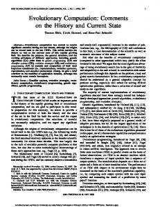
We use our algorithms to design a system for multimedia presentation designs. One dimensional relations are used for scheduling and two dimensional relations are for layout generation. We try to provide a set of relation ICONs and a graphical user interface for the user to click, drag and drop multimedia resource relations. Thus, the necessary information of generating schedule and layout is declared. When a user is about to change the relation between two resources, the user does not need to worry about relations of other objects. This is the most important advantage of using our system. However, considering the amount of relations, it is quite difficult for us to design and for the user to use 13 1-D relation ICONs and 169 2-D relation €CONS. Therefore, synthesizing relations is a need. Assuming X . d denotes the duration of interval X I and Y . d is the one for Y , and according to the parameterized relations discussed in section 3.3, we combine the following five relations into the p a r a l l e l ( X , Y , n ) relation: Table 3: Combining Parallel Relations Parameterized Relations epuaZ(X, Y ) d u r i n g ( X , Y ,n ) starts(X, Y ) finishes(X,Y ) overlaps-’(X, Y , n)
Conditions n = 0 A Y.d = X.d n>OA Y.d>n+X.d n = 0 A Y.d > X.d n > O A Y.d=n+X.d n > 0 A Y.d < n + X.d
For example, given the relation p u r u l l e l ( X , Y , n ) , if n > 0 and Y . d > n X . d , then the relation during(,Y, Y , n ) is used by the system for scheduling. Note that p a r a l l e l ( X , Y , n ) is specified by the user via an ICON. But X . d and Y . d are retrieved from the resource database. Similarly, we combines two relations into the sequential( X ,Y , n ) relation:
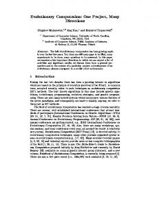
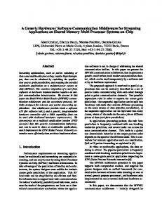
(and their inverse relations) cover all 13 relations introduced in [l], using our two ICONs and the graphical user interface enables the user to specify any temporal relations between two multimedia resources. To design spatial ICONs is a little complicate. Based on the two temporal ICONs, we derive four basic spatial ICONs. Note that, the concepts of parallel and sequential relations are used in the spatial ICONs for controling object overlaping. Two rectangles can be parallel to each other in the X or in the Y coordinate. Only if both coordinates overlap, the two rectangles overlap physically, as shown in the parallel-parallel spatial ICON. The other three basic spatial ICONs contain rectangles either overlap in zero or one coordinate. Thus, those rectangles do not overlap with each other physically. For the two temporal ICONs, inverse relations can be specified by swapping the two multimedia resources. However, in the case of spatial ICONs, inverse relations occur either in the X or in the Y coordinate (or both). Thus, the swapping of resources in X and Y coordinates are dependent. Therefore, for each basic spatial ICON, there are four possible cases. Considering the X box (i.e., resource X) fixed in coordinate, the Y box (i.e., resource Y) can be on the north-west, the north-east, the south-west, or the south-east of the X box. However, the north-west case and the south-east case are inverse relations, as well as the north-ease case and the south-west case. Thus, only four spatial ICON variations are used. Similar t o specifying a timing parameter of a temporal relation, spatial ICONs use box “m” and “n” for spacing information in the X and the Y coordinates. Two dimensional relations are extended from those of 1-D’s. Since the four basic spatial ICONs are extended from the parallel and the sequential temporal ICONs, and all inverse relations can be derived, we found that the 8 spatial ICONs covers all cases of spatial relations.
+
Table 4: Combining Sequential Relations Parameterized Relations b e j o r e ( X , Y ,n ) meets(X. Y )
Conditions n>O
n=O
We design two ICONs for the parallel and the sequential temporal relations. The boxes denoted by “X” and “Y”are to keep resource ICONs which represent multimedia resources selected by the user via our resource browser. The small boxes denoted by “n”are filled with integers by the user for the timing parameter of those two relations. Since the two temporal relations
5.1
Linking the Temporal and the Spatial Relations
A presentation schedule is a collection of temporal intervals. Each interval has a starting point and an ending point. These points change the state of a presentation. A state change point in a presentation, in our definition, is a time point which contains at lease one starting or ending point of temporal intervals, except the ending point(s) of the last interval(s). Since multimedia presentations are dynamic, the definition of presentation layout is with respect to a time point. It is the state change points that we consider for these time points. The layout of presentation with respect to a state change point is defined to be the collection of multimedia resource locations on the screen, starting from the state change point and ending at the next state change point (exclusive), or the end of the presentation. The relative time table discussed in section 3.3 con-
234
Authorized licensed use limited to: Tamkang University. Downloaded on March 28,2010 at 22:39:24 EDT from IEEE Xplore. Restrictions apply.
I
tains the starting point of intervals. The ending points are easily computed by using the relative time table and the duration labels. Therefore, a set of state change points is computed. For each point in the set, we maintain links to the objects in the spatial relation POSets. Thus, the layout design with respect to each state change point is constructed and stored.
6
computing.
Acknowledgement I would like to thank all members of the MINE Lab, especially Mr. F. Y. Jeng, Mr. Steven K. Lo, Mr. Szu-Jan Fu, and Mr. Julian B. Chang for their implementation of the presentation system.
Conclusions References
In this paper, we analyze temporal interval relations and propose four domains for relation composition. We provide a set of algorithms for the automatic generation of multimedia presentation from temporal and spatial relations among multimedia resources. Possible conflicts of relations are eliminated. We then extend the algorithms to compute relations of objects in an arbitrary n-dimensional space. The algorithms are used in a system that uses an ICON programming technique for multimedia presentation designs. The algorithms proposed in this paper can be used in other computer applications, for instance, a project management system. A project contains a number of tasks. Two tasks may be performed either concurrently or sequentially. They may start or end at the same time. Or, the first task may be performed after eighty percents of the second is complete. In such a management system utilizes our algorithms, if the user specifies the temporal relations of tasks, the project schedule can be generated automatically. The system proposed in this paper takes a complete different approach from a system of similar purpose that we have developed [3]. Our previous work uses temporal interval relations and artificial intelligence techniques to assist the user for multimedia presentation designs. The inference rules are intuitive and not quite feasible in some situations. Also, spatial relations were not discussed. In this paper, procedural algorithms use a graph representation provide a total solution of the automation. And the spatial composition of multimedia resources is newly proposed. However, in this new presentation system, we have not yet take as considerations the hardware limitations. Physically, it is difficult to present more than two sound wave resources simultaneously for most sound devices of nowaday personal computers. We will implement another checking mechanism to alert the user for this situation. Also, in [3], we discussed a number of rules to cut or extend multimedia resources in order to make a better presentation. We are now incorporating these rules in our new system. The main contributions of this paper are in its theoretical analysis of interval relation compositions and a systematic approach toward automation. We hope that, with our analysis and algorithms, the knowledge underlying temporal interval relations can be used in many computer applications, especially in multimedia
James F. Allen “Maintaining Knowledge about Temporal Intervals,’’ Communications of the ACM, Vol. 26, No. 11, 1983. Thomas D. C. Little and Arif Ghafoor “IntervalBased Conceptual Models for Time-Dependent Multimedia Data,” IEEE transactions on knowledge and data engineering, Vol. 5, No. 4, 1993, pp 551-563. Timothy K. Shih, Steven K. C. Lo, Szu-Jan Fu, and Julian B. Chang, “Using Interval Temporal Logic and Inference Rules for the Automatic Generation of Multimedia Presentations,” in Proceedings of the IEEE International Conference on Multimedia Computing and Systems, Hiroshima, Japan, June 17 - 23, 1996, pp. 425 - 428. Timothy K. Shih, Chin-Hwa Kuo, Huan-Chao Keh, Chao T. Fang-Tsou, and Kuan-Shen An, “An Object-Oriented Database for Intelligent Multimedia Presentations,” in proceedings of the 1996 IEEE International Conference on Systems, Man and Cybernetics, Beijing, China, October 14 - 17, 1996. Michael Vazirgiannis, Yannis Theodoridis, and Timos Sellis “Spatio - Temporal Composition in Multimedia Applications,” in proceedings of the International Workshop on Multimedia Software Development, March 25 - 26, Berlin, Germany, 1996, pp 120 - 127. Thomas Wahl, et. al., “TIEMPO: Temporal Modeling and Authoring of Interactive Multimedia” in proceedings of the international conference on multimedia computing and systems, Washington DC, U.S.A., May 15-18, 1995, pp 274-277.
235
Authorized licensed use limited to: Tamkang University. Downloaded on March 28,2010 at 22:39:24 EDT from IEEE Xplore. Restrictions apply.