Towards Making Agent UML Practical: A Textual Notation and a Tool Michael Winikoff RMIT University Melbourne, Australia
[email protected] Abstract Design notations play an important role in designing software. Agent UML (AUML), which extends the widelyused UML notation, has proposed a number of notations for modelling agent systems. Arguably the most influential of the AUML notations has been the sequence diagram for defining interaction patterns between agents. However, AUML is not precisely and formally defined, and there is very little in the way of tool support available. In this paper we describe initial steps at resolving these two issues: we precisely define the syntax of (a subset of) AUML by using a textual notation, and we describe a tool that takes a textual AUML protocol and automatically generates the standard graphical rendition.
1. Introduction Design notations play an important role in the design of software. Arguably the best-known and most widely adopted notation for designing software today is the Unified Modelling1 Language (UML2 ) [10]. Agent UML (AUML3 ) extends the UML for designing agents. It proposes a number of notations including sequence diagrams, interaction overview diagrams, communication diagrams and timing diagrams [6]. Of these the sequence diagram4 is arguably the most novel, and more importantly, has been the most influential: a number of methodologies have adopted it for describing patterns of interaction between agents, including Prometheus [11], Gaia [8], and Tropos [1]. 1 2 3 4
Usually spelled “Modeling”. http://www.uml.org http://www.auml.org In earlier AUML publications this was referred to as “interaction protocols”. We shall use the terms “interaction protocol” and “sequence diagram” interchangeably in this paper. We shall also sometimes use “AUML” as shorthand for “AUML interaction protocol”.
Unfortunately, AUML suffers from two issues. Firstly, the notation itself is not formally and precisely defined; and secondly, tool support for AUML is largely non-existent. In this paper we describe work that makes progress towards addressing both these issues: we provide a precise syntax for a (subset) of AUML, and we describe an implemented tool that takes AUML protocols in an easilywritten textual format and automatically generates the standard graphical representation. Note that all of the AUML figures in this paper were generated by the tool. In the longer term we see the textual notation as an alternative to the graphical presentation. We envisage that the textual notation be used internally in a graphical tool, and that although users will have access to the textual notation, they will not be required to use it to develop their sequence diagrams. We begin with a brief description of the AUML notation (section 2). We then present a precise definition of a (subset of) AUML using a textual notation (section 3), followed by a description of the tool that we have developed (section 4). We then discuss related work (section 5) and conclude (section 6).
2. The AUML Notation for Protocols The AUML notation for protocols is similar to version 2.0 of the UML [10]. An interaction protocol (“sequence diagram”, see figure 1 for an example) consists of a number of lifelines, each labelled with an agent class name in a box at the top of the lifeline. Messages are depicted by labelled arrows between lifelines, and time increases down the page. Agent UML allows for alternatives, parallelism and so on to be specified using boxes. A box surrounds a part of the sequence diagram and has a type such as “Alternative”, “Option”, or “Parallel” (given in the top-left corner of the box). Boxes can contain messages and other boxes and can be divided into a number of regions, separated from each other by heavy horizontal dashed lines. Each region can contain a guard, depicted as text in square brackets, specifying a condition on that region being selected.
sd AUML Notation alternative [guard] An agent
message
Another agent
box goto A region
alternative [guard] ref
sd Simple Example Alice
Bob
message RefAnother to another protocol region
goto
Speak English? box
alternative
Yes No
Figure 1. A Simple AUML Protocol AUML defines a number of box types including Alternative, Option, Break, Parallel and Loop.
A region
2. Additional AUML Notation ref FigureRef to another protocol Another region
Each goto must have a single corresponding label in the protocol, and when a goto is reached execution continues at the corresponding label. label box
• Stop: Depicted as an X on the lifeline of an agent, this region denotes “the end ofAparticipation of a lifeline in the communication” [6, section 2.9].
• Break: Terminates the interaction. It isn’t entirely clear from [6] whether other threads of the interaction are terminated at the start of the break box or at the end.
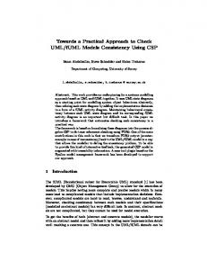
Figure 3 shows an English auction protocol. The protoAnother region col begins with the Initiator informing the Participants of the start of the auction. This is then followed by a number of rounds each of which consists of a call for proposals (cfp) from the Initiatorlabel to Participants, followed by a response from the Participant. If a Participant’s response is not-understood, then that participant does not continue to interact in the protocol. Otherwise, the response is a price (propose-price) which is accepted or rejected by the Initiator. Finally, the Initiator informs the Participants that the auction has finished (inform-end-of-auction), and if the price reached exceeds or equals the reserved-price then the Initiator requests the item.
• Parallel: Specifies that each of the regions takes place in parallel and the sequence of messages is interleaved.
3. A Textual Format for AUML
• Alternative: Exactly one5 of the box’s regions is executed. For example, the simple protocol in figure 1 shows a message from an agent of type Alice to an agent of type Bob followed by either a reply of “Yes”, or a reply of “No”. • Option: This box type can only have a single region and specifies that this region may or may not occur.
• Loop: Can only have a single region. Specifies that the region is repeated some number of times. The tag gives the type (“Loop”) and also an indication of the number of repetitions which can be a fixed number (or a range) or a Boolean condition [10, page 413]. By default “Loop” on its own means “zero or more times”. In addition to these box types AUML provides a number of other constructs (see figure 2): • Ref: This box type is a little different in that it doesn’t contain sub-components, only the name of a protocol. The interpretation of the Ref box is obtained by replacing it with the protocol it refers to. • Continuations: incoming and outgoing continuations are just (respectively) labels and gotos. Both continuations are depicted by rounded rectangles; outgoing continuations (goto) have a right pointing triangle on their right side whereas incoming continuations (labels) have a right pointing triangle on their left side. 5
label
Actually it is possible for none of the regions to be executed if all guards are false. This can be avoided by having an “else” guard.
We have two primary reasons for defining a textual format for AUML. The first, and more important, is that defining the syntax of a textual notation is considerably simpler than defining the precise syntax of a two-dimensional graphical notation. The second reason is that having defined a textual notation, one can use it to write down AUML interaction protocols. There are a number of reasons why we might want to use a textual notation to write AUML protocols, rather than using the graphical notation. The obvious reason is that there are, to the best of our knowledge, no interactive graphical tools currently available that support the new version of AUML. However, even if there were interactive graphical tools available, textual notations are still widely considered to have some significant advantages (as well as disadvantages). For example, Hunt and Thomas [7, Chapter 3] argue that the benefits of textual formats are insurance against obsolescence, leverage (of a range of existing tools, from version control to editors to compilers), to easier testing. Raymond [13, Chapter 5] argues that textual formats are preferable because of interoperability, transparency, and extensi-
sd English Auction Initiator
Participants inform-start-of-auction
loop
cfp
alternative
not-understood(syntax-error)
not-understood(ontology)
propose-price alternative
accept reject
inform-end-of-auction option [actual-price >= reserved-price] request
Figure 3. English Auction Protocol
auml ::= start agentdef* pe* finish H start ::= start protocol-name H agentdef ::= agent short-name long-name H pe ::= message from-name to-name message-label H | boxstart boxcontents boxend | sub protocol-name H | goto label-name H | label label-name H | stop agent-name H boxstart ::= box boxtype H | box boxtype H guard guard-text H boxtype ::= alternative | option | . . . boxend ::= end boxtype H boxcontents ::= pe* | pe* nextregion boxcontents nextregion ::= next H | next H guard guard-text H “pe” is short for “protocol element” Entities ending with “name” are strings, as are “guard-text” and “message-label”. “H” is used to denote a newline. Terminal symbols are in bold and “*” is “zero or more”. Figure 4. The AUML Notation messages whereas the longname is used in the box at the top of the lifeline. This avoids having to repeatedly type the long agent name in messages. • Define messages between agents (message)
bility. Additionally, with a clearly defined textual format it is easier for data to be generated by other programs. Our experience in using the AUML textual format for writing protocols echoes the accepted wisdom: we have found that writing down protocols is fast and easy, and that editing protocols is easy (copying a part of a protocol, making global substitutions to names, searching for names etc.). However, it should be made clear that we are not proposing that the usual graphical rendition be replaced with a textual notation. The primary reason for using a textual notation is to define precisely the syntax of the AUML. Being able to write sequence diagrams textually is an “added bonus” which is quite useful given the current state of tool support for AUML, but which will decrease in importance as tools supporting the AUML become more available and more mature. A textual AUML protocol (see figure 4) consists of a sequence of commands (one per line). The first line defines the name of the protocol (start name) and the last concludes the protocol (finish). Commands in between are used to: • Define agents (agent shortname longname) – the shortname is used to refer to the agent when sending
• Define the start and end of boxes (box and end) • Define the boundary between regions within a box (next) and guards (guard) • Define Ref boxes (sub) • Define continuations (goto and label) • Define the end of an agent’s participation in the protocol (stop) For example, the following textual protocol corresponds to figure 3. start sd English Auction agent i Initiator agent p Participant message i p inform-start-of-auction box loop message i p cfp box alternative message p i not-understood(syntax-error) stop p next message p i not-understood(ontology) stop p next
start query protocol agent I Initiator agent P Participant box alt message I P query-if …
backup then guard to break a long guard over two lines. auml.pl
Tcl/tk program
wish
.eps file
Figure 5. The AUML Tool message p i propose-price box alternative message i p accept next message i p reject end alternative end alternative end loop message i p inform-end-of-auction box option guard [actual-price >= reserved-price] message i p request end option finish Note that the indentation is ignored by the tool, although it is, of course, very important to human readers.
4. Tool Support for AUML We have developed a prototype tool which takes an AUML protocol, in the textual format described in the previous section, and generates the standard graphical rendition. The tool is completely automatic: it lays out the graphical elements without user interaction. The tool is freely available6 and requires Perl and Tcl/Tk. The tool uses Tcl/Tk’s canvas widget to draw the protocol and then export the diagram to encapsulated postscript, which can then be included in documents, or converted to a range of formats. Figure 5 summarises this process. Although the tool lays out the interaction protocol’s graphical elements automatically, and generally does a fairly good job, sometimes it is desirable to manually fine-tune the appearance or layout of a protocol. The tool supports this by adding a number of declarations to the textual notation defined in section 3. These declarations include: • backup: moves the current vertical position up. For example the sequence message then backup then message will show the messages being sent at the same time. Another common sequence is guard then 6
From http://www.cs.rmit.edu.au/∼winikoff/auml
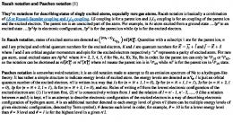
• agsep+: is followed by a number. It increases the space between agents’ lifelines by that amount. • agwidth+ is followed by a number, and increases the width of the box containing the labels on the agents’ lifelines by that amount. • tagwidth+ is followed by a number. It increases the width of the tags of boxes by this amount. • inittagwidth+ is the same as tagwidth+ but affects the initial tag containing the name of the protocol. The protocol in figure 3 was produced by adding the following declarations to the protocol specification given in the previous section: inittagwidth+ 50 agsep+ 50 Our experiences with the tool have been very positive. The textual notation is very easy to learn and it has been used by undergraduate students. Writing interaction protocols textually is quite fast, and in particular it is faster than interacting with a GUI. Finally, the protocols produced by the tool are visually attractive and do not contain inconsistent spacing, since the layout is done automatically by the tool. Additionally, the notation and tool have proved to be easy to extend with additional constructs. For example, recent work on extending Prometheus to be more goaloriented [9] added goals to interaction protocols (depicted as boxed text on agents’ lifelines). The tool was extended with a new command goal agentname goal. Another, more significant, extension was done in the context of the Hermes methodology for designing flexible agent interactions [2]. One of the design artefacts produced is an Action Message Diagram (see figure 6) which depicts actions (boxed text on agent lifelines), along with messages that they trigger. Actions can be final (depicted with a thicker border) and take place in order to achieve Interaction Goals. This is shown with a grey shaded region for each Interaction Goal. Again, the tool was extended with new commands for expressing these constructs. Both these modifications were very easy to perform: the tool was extended in a matter of a few hours by the author.
5. Related Work Huget [5] has proposed an XML-based machinereadable representation for AUML protocols. However, the notation, which is based on the earlier version of AUML, is considerably more verbose: the English auction protocol is encoded in 250 lines of AXF. Additionally, the notation is not human-readable. Although our notation is
Customer
Merchant
Negotiate Details ProposeDetails PROPOSE: blue Monitor ConsiderDetails AcceptDetails ACCEPT-PROPOSAL TerminateIG
Negotiate Price ProposePrice PROPOSE: price 100 ConsiderPrice AcceptPrice ACCEPT-PROPOSAL TerminateIG
Figure 6. Action Message Diagram (From [2]) not XML-based (and hence less “buzzword-compliant”), it is just as formal, easier to parse, and considerably easier for humans to read and write. Doi et al. [3] have proposed a textual notation for describing protocols. The notation is not intended to capture AUML protocols, but to serve as a stepping-stone between AUML and implementation. Their notation covers only a part of AUML7 They give an encoding for the English auction protocol which takes around 130 lines of IOM/T. However, the IOM/T description does include additional details, such as the contents of messages. By contrast, using our notation the English Protocol is under 30 lines. Tool support for AUML is fairly limited. Viper [14] is a graphical editor for the earlier version of AUML, which is very different to the current version. The only tool that we are aware of that supports the current version of AUML is the Ingenias Development Kit (IDK) which includes sup7
“The current version [sic] IOM/T can not fully represent interactions which are equivalent to design in AUML. . . . there are not the notations which represent CombinedFragment. Only CombinedFragments whose interaction operator [sic] are “Loop” can be represented by “while” structure”. [3, Section 2.7].
port for an AUML-like notation for protocols. However, this seems to be in alpha version and is limited (“So far, only alternatives, basic messages, and subprotocols have been implemented.” – IDK reference manual8 , page 21). Recent work by Ehrler and Cranefield [4] has described a tool for executing AUML protocols. Protocols are created by directly editing XML corresponding to the meta-model, i.e. there is no graphical editor. Additionally, the AUML protocols are augmented with additional information, and at the time of publication of [4] (mid 2004) the PAUL9 tool could only handle the Alternative box type and was limited to two agent lifelines. Although UML 2.0 is supported by tools, there are differences between UML 2.0 and AUML. For example, in UML 2.0 object lifelines have activation boxes showing when objects are active.
6. Conclusion We have presented a concise and precise textual notation for AUML protocols (“sequence diagrams”). We have also described a tool we have implemented which takes AUML protocols in this textual format and produces a graphical rendition, with the layout of graphical elements being done automatically. Given the lack of tool support for AUML today the textual notation and supporting prototype tool provide a surprisingly practical way of drawing AUML sequence diagrams. The notation and tool have been used by colleagues of the author and by students (both postgraduate and undergraduate). Our experience has been that the notation is easy to learn, surprisingly easy to read, and quick and easy to write. Although the tool has proven quite useful in its current form there is, as always, scope for further work. The tool supports a significant part of the AUML sequence diagram notation, but not all of the notation. Some aspects that are not currently supported include cardinality annotations on messages, gates, and different message types (e.g. asynchronous messages, and messages from a lifeline to itself). The notation could also be extended to cover AUML’s interaction overview diagrams. Another potential area for further work is in using the tool as the basis for graphical tools. An obvious tool is an AUML sequence diagram editor. However, other tools are possible. For example, it would be quite straightforward to extend the Tcl/Tk code generated to allow for graphical tracing by highlighting messages as they are sent and received. This could be used to visualise the results of mon8 9
http://ingenias.sourceforge.net, accessed 19th May 2005. Plug-in for Agent UML Linking.
itoring the execution of interaction to detect bugs in the implementation [12]. Our experience in developing AUML protocols has highlighted a number of areas where the notation could do with improvements. One key area is dealing with multiple instances of a given agent type. For example, in auctions there are N instances of bidder agents. AUML does not make it easy to capture the parallelism associated with a broadcast message and the point at which the different threads need to synchronise. Finally, another area for future work is formally specifying the semantics of AUML.
Acknowledgements I would like to acknowledge the support of Agent Oriented Software Pty. Ltd. and of the Australian Research Council (ARC) under grant LP0453486. I would also like to thank Lin Padgham and David Poutakidis for discussions of issues relating to AUML.
References [1] P. Bresciani, P. Giorgini, F. Giunchiglia, J. Mylopoulos, and A. Perini. Tropos: An agent-oriented software development methodology. Journal of Autonomous Agents and MultiAgent Systems, 8:203–236, May 2004. [2] C. Cheong and M. Winikoff. Hermes: Designing goaloriented agent interactions. In Proceedings of the 6th International Workshop on Agent-Oriented Software Engineering (AOSE-2005), July 2005. [3] T. Doi, N. Yoshioka, Y. Tahara, and S. Honiden. Bridging the gap between AUML and implementation using IOM/T. In Second International Workshop on Programming MultiAgent Systems: Languages and Tools (ProMAS), 2004. [4] L. Ehrler and S. Cranefield. Executing agent UML diagrams. In Proceedings of the third international conference on Autonomous Agents and Multi-Agent Systems (AAMAS), pages 906–913, 2004. [5] M.-P. Huget. A language for exchanging agent UML protocol diagrams. Technical Report ULCS-02-009, The University of Liverpool, Computer Science Department, 2002. [6] M.-P. Huget and J. Odell. Representing agent interaction protocols with agent UML. In Proceedings of the Fifth International Workshop on Agent Oriented Software Engineering (AOSE), July 2004. [7] A. Hunt and D. Thomas. The Pragmatic Programmer: From Journeyman to Master. Addison-Wesley, 2000. [8] N. Jennings, D. Kinny, M. Wooldridge, and F. Zambonelli. The Gaia methodology. In F. Bergenti, M.-P. Gleizes, and F. Zambonelli, editors, Methodologies and Software Engineering for Agent Systems, chapter 4. Kluwer Academic Publishing (New York), 2004. [9] J. Khallouf and M. Winikoff. Towards goal-oriented design of agent systems. In First international workshop on Integration of Software Engineering and Agent Technology (ISEAT 2005), 2005.
[10] UML 2.0 superstructure specification. Object Management Group, available from www.omg.org, document ptc/03-0802., 2003. [11] L. Padgham and M. Winikoff. Developing Intelligent Agent Systems: A Practical Guide. John Wiley and Sons, 2004. ISBN 0-470-86120-7. [12] L. Padgham, M. Winikoff, and D. Poutakidis. Adding debugging support to the Prometheus methodology. Engineering Applications of Artificial Intelligence, 18(2):173–190, 2005. Special issue on Agent-oriented Software Development. [13] E. S. Raymond. The Art of UNIX Programming. AddisonWesley, 2004. [14] C. Rooney, R. Collier, and G. M. P. O’Hare. VIPER: VIsual Protocol EditoR. In 6th International Conference on Coordination Languages and Models (COORDINATION 2004), 2004.