Towards Optimal Worker Assistance: A Framework for Adaptive Selection and Presentation of Assembly Instructions A. Bannat, F. Wallhoff, G. Rigoll, F. Friesdorf, H. Bubb, S. Stork, H. J. M¨uller, A. Schub¨o, M. Wiesbeck, M. F. Z¨ah
Abstract— Traditional systems for digital assistance in manual assembly, e.g. optical displays at the work place, are inherently suboptimal for providing efficient and ergonomically feasible worker guidance. The display of sequential instructions does not offer an increase in productivity beyond a certain degree. Little situational support and the resulting deterministic guidance lead to a reduced acceptance by the worker. A solution to this discrepancy is seen in an adaptive and cognitive system for worker guidance. Information from an adaptive process model and findings from experiments about human cognition are facilitated to provide the worker with assistive information, adapted to the situation and cognitive state of the worker.
in this way, new technologies for efficient worker guidance will be usable [6]. In the following sections: A description of the flexible process model is given (Sec. II), the experimental setup for investigation of human cognitive processes is presented (Sec. III), methods and technologies for sensor-based monitoring of the manual workplace are described (Sec. IV), and an overview of the overall system architecture is given (Sec. V). Finally, an outlook is made.
I. I NTRODUCTION
Representative digital systems for assistance in manual assembly situations in their current concepts are laid out suboptimally. These systems do not offer an efficient and at the same time ergonomical worker guidance [7]. The root cause thereof lies in the use of a single assembly sequence for planning the assembly system as well as for guidance of the worker. This assembly sequence, derived from precedence graph of a product, is only optimal and ultimately feasible under the view of long-term and hitherto known factors [8]. However, during runtime (i. e. assembly of a product) influences from the factory environment or variations in apriori known conditions are not taken into account for the display of assembly instructions. Changes in sequence on complex products initiated by the worker cannot be reacted upon.
Currently, a well-experienced work force on the shop floor is required to dynamically adapt to the current state of the process [1]. Consequently, complex capital products, e.g. machine tools, are manufactured in continuous manual assembly by teams of expert technicians. The reason for this originates from the failure to succeed in a detailed preliminary planning and usage of such to drive a guidance system because of the high dissimilarity and complexity of the goods [2]. Conventional, similar systems lack the ability of cognition, leading to serious deficiencies when acting in complex environments, especially in the context of humanmachine-interaction [3]. Known systems for worker guidance operate on manually derived and statically compiled assembly plans [4][5]. Furthermore, literature shows mainly technical implementations of guidance systems based on Augmented Reality (AR). However, a successful application has to support the planning entity methodically sound. Only Manuscript received August 1, 2008. This work is supported in part within the DFG excellence initiative research cluster Cognition for Technical Systems — CoTeSys. CoTeSys partner institutions are: Technische Universit¨at M¨unchen (TUM), Ludwig-Maximilians-Universit¨at (LMU), Universit¨at der Bundeswehr (UBM), Deutsches Zentrum f¨ur Luft- und Raumfahrt (DLR), and Max-Planck-Institute for Neurobiology (MPI), all in Munich. A. Bannat, F. Wallhoff, G. Rigoll are with Technische Universit¨at M¨unchen, Department of Electrical Engineering and Information Technology, Institute for Human-Machine Communication (e-mail:
[email protected]). F. Friesdorf, H. Bubb are with Technische Universit¨at M¨unchen, Department of Mechanical Engineering, Institute of Ergonomics (e-mail:
[email protected]). S. Stork, H. J. M¨uller, A. Schub¨o are with Ludwig-MaximiliansUniversit¨at M¨unchen, Department of Psychology, Experimental Psychology (e-mail:
[email protected]). M. Wiesbeck, M. F. Z¨ah are with Technische Universit¨at M¨unchen, Department of Mechanical Engineering, Institute for Machine Tools and Industrial Management (e-mail:
[email protected]).
II. P ROCESS M ODEL FOR M ANUAL A SSEMBLY
12
6 14
3 7
15 Fig. 1. Graph-based representation of the Assembly State Vector according to [9].
Several authors have modeled the entirety of possible assembly sequences for a single product in graph-based structures (e. g. Fig 1) [9][10][11][12]. These approaches have in common, that the main intention lies in reducing the combinatorial entirety of assembly sequences to the ones deemed as feasible. An assembly task is said to be geometrically feasible if there is a collision-free path to
From: 1st Intern. Cotesys Workshop 2008, Technische Universität München
bring the two subassemblies into contact from a situation in which they are far apart. And an assembly task is said to be mechanically feasible if it is feasible to establish the attachments that act on the contacts between the two subassemblies that correspond to a state (not necessarily stable [11]. All operations of an assembly sequence have to fulfill both conditions strictly. However, none of the existing graph-based representations allow for the selection of assembly tasks in real-time. This hinders the delivery of situationally adapted instruction to the worker. A key to solving these issue is seen in the application of adaptive and cognitive methodologies for the generation of assembly tasks. These require environmentallydependant and situation-dependently triggered paths on statebased graphs. A mapping of the product’s processing states and a dynamic determination of the otherwise sequential tasks is achieved by the graph-based structure shown in Figure II [13].
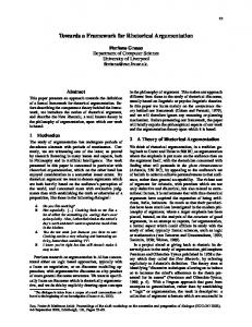
Fig. 2.
Schematics of a state-based assembly graph [13].
Every product’s set of instructions is defined by an stgraph. The product-specific graphs are deducted from construction and assembly-related information. In accordance with Figure II, the source vertex s represents the initial state of the product to be assembled (state zstart ) and the sink vertex t represents the target state of the fully assembled product (state ztarget ). The edges of the graph (e. g. Astart,I ) symbolize assembly task instructions. The execution of such by the worker will transfer the work piece in focus from one state to another (e. g. zstart to zI ). The path from the initial state zstart to the target state ztarget leads across the respective major intermediate states zstart to ztarget−1 (zII ). The minor intermediate states shown in Figure II (zI,1,0 , zI,1,1 , ...) are reachable via an increased degree of detail of the assembly task instructions. If a vertex has more than one outgoing edge Ai,j , then alternative assembly sequences or alternative parts can be disposed of. The graph will not allow for cycles, under the presupposition that a disassembly of products to be built shall not be possible. This simplification entails, that the target state of the fully assembled product (state ztarget ) is reachable on a path from every state of the graph. Therefore, there are no states which would hinder a further assembly towards the target state. A future extension of the presented concept will account for disassembly tasks and is in the scope of the current research activities.
III. I NVESTIGATION OF C OGNITIVE P ROCESSES DURING M ANUAL A SSEMBLY Manual assembly tasks involve the whole loop of cognitive functions from perception, attentional selection, working memory to action planning. For example, the type and amount of necessary parts for a workpiece has to be identified from the instruction and memorized for further action planning. Next, the relevant action, i.e. a reaching movement for an assembly part, has to be selected and executed. In order to describe and investigate the relevant processing stages in more detail the information processing framework can be applied, which assumes that the sub-processes are passed through serially [14]. Adaptive assistance and facilitation of the assembly work requires the adequate support of each of these sub-processes, especially if new or highly complex tasks have to be executed. A catalogue of neuro-cognitive methods for the experimental investigation of human performance and bottlenecks in complex assembly situations has been defined [15] and implemented partly in a working scenario [16] [17]. The methods range from behavioural measurements like error rates, completion and dwell times over motion and eye tracking to event-related brain potential measurements extracted from the EEG. For those measurements a Polhemus motion tracker system, an Eyelink remote eyetracker system as well as a video camera were integrated in a standard workbench. For instruction presentation, the workbench was equipped with a projector and a front-surface mirror enabling a projection which covers the whole working area (Fig. 3). This setup can present contact analog information, for example a highlighting of the relevant boxes where parts for the current assembly step are stored. Accordingly, the worker can be supported via context sensitive, adaptively generated instructions at the right time, location and with appropriate content. Additionally, a TFT monitor was integrated for the presentation of alternative or complimentary information. Two left and right foot pedals were applied for the usercontrolled timing of relevant information presentation. This interface was chosen in order to not disturb the ongoing assembly process during the interaction, following the account of Wickens who described a model of distributed resources for the prediction of mental workload [18]. The described augmented workbench serves both as a research tool for the experimental investigation of cognitive processes in manual assembly, as well as a platform for the implementation of the assistive system, leading to a more efficient manual assembly performance. The value of the concept was tested within experiments, where different instruction modes and complexity of a manual assembly task were varied in order to manipulate respective processing resources. The impact of different instruction modes and task complexity on the assembly times and on the first goaldirected movement during an assembly task was investigated. A. User Interface: Foot Pedals An analysis of pedal presses, motion tracker data together with video records shows that the foot pedals can be used
1x 2x 1x
1x
B 3x 6x
A
C
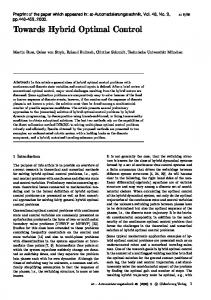
Fig. 4. Fig. 3.
Grasping movement to a highlighted box.
Workbench and instructions [17]
as a user interface without the disturbance of the ongoing assembly process. Moreover, the interface conveys parallel working processes like e.g. quick checking of correct part assembly in previous substeps during the assembly procedure. It enables the observation of the exact point in time when new information is needed and of working strategies[17]. B. Task Complexity The effect of task complexity as a manipulator of working performance was demonstrated in the dependent step times. Certain assembly step classes (i.e. gear fitting) lead to longer mean step times than others (i.e. gear assembly) with the same amount of parts, in accordance with difficulty ratings of the subjects [16]. Moreover, step times varied within one step class as a linear function of the amount of parts. Therefore, the observed mean assembly times with a certain step classes can be used together with the amount of parts for the prediction of completion times and mental workload during ongoing assembly [17]. C. Instruction Mode Results demonstrate an advantage of contact analog instruction presentation. With complex tasks (i.e. gear fitting), the assembly times per part was about 10 seconds shorter with contact analog instruction mode in comparison to monitor presentations [16]. Motion tracker data deliver more detailed information on the subprocesses involved. So, also the onset latency of the first movement to a box was shorter with the contact analog mode (see Fig. 4). Moreover, peak velocity and peak acceleration were higher under this condition, possibly because participants were more confident concerning the relevant box position. Therefore, it seems that the highlighting of boxes enabled to select the relevant part position and to shift attention faster resulting in an overall decreased movement onset time and higher movement velocities [19]. The workplace augmentation methods used here will be improved and refined while adding sensors to the experimental setup, i.e. for box detection and hand tracking, as described in the next section.
IV. S ENSOR - BASED M ONITORING OF M ANUAL W ORKPLACE To be able to monitor actions of a human worker, his workplace has to be equipped with sensors. For more details refer to [20]. The main components are explicit as well as implicit input modalities. Through explicit inputs it is possible to directly interact with the system, whereas implicit input is generated by monitoring the worker in the background. Here, vision-based sensors are used for tracking events in the background, with a global top-down view camera mounted above the workbench. This device has the overview over the entire work-area and makes it possible to watch the actions on the workbench and locate objects on the surface. These observations generate events that are used to adapt the assembly-plan. The following paragraphs describe how these events are produced. A. Box detection It is necessary to know what parts have been taken out of which box on the workbench. So, the boxes have to be located in a first step. This is done by analyzing the images taken from a top-down view camera. The boxes used vary in color and size. To detect their positions in pixel coordinates, a color-based image segmentation is performed. To extract the relevant areas in the image-plain, thresholding filters in the HSV-color-space are used [21]. After converting the image into binary masks corresponding to each box color, a classification is done to determine whether an area is a box or not. The extracted regions are labeled, using connected-components analysis. These regions are further on called blobs. To identify blobs as boxes, their dimensions have to be nearly rectangular and cover a certain area in the image plain. Figure 5 shows a typical result of the box detection module on the workbench. The center of gravity for each box is calculated and illustrated as a dot with the corresponding box-color. This modality allows a free distribution of the storage boxes on the workbench and the worker can choose where he wants to place them. One could assume, that a frequently used part is stationed closer to the work-area, as a rather rarely required one.
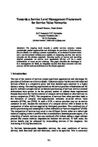
Fig. 5. Image-based workbench observation: box detection and motion recognition; picture from [20].
to get accurate information about the location of the worker’s hand. The box-tracker provides the system with the positions of the boxes on the surface, presented in section IV-A. These raw data are used to generate a hand-over-box-event. The distance between the centers of gravity of hand and box is calculated with the city block distance for 2D-points and stored as dbox2hand . The next step is to decide above which box the hand is hovering. The indicator telling if a hand-over-box-event has occurred follows the condition: if the distance between the box and the worker’s hand is equal or less than 50 pixels, the value of the hand-over-box-event is set to true. Otherwise it is set to false. The value 50 pixels results from the approximated diameter of a box in pixels. In Figure 6 the allocation of a box to the hand position is depicted. The accordant box is highlighted
B. Hand detection To decide which part has been taken out of which box, it is necessary to know, where the hand of the human worker is. For that, two operations are performed: restriction of search region in the image and detection of human skin. 1) Motion-Detector Module: Under the assumption that the worker’s hands are moving while he is performing his task, only those areas are interesting, where the image has changed during an analysis-period. A motion-detector has been implemented for cropping regions with movement. If the number of changed pixels arises above a certain threshold, the corresponding regions are further analyzed. In Figure 5 the result of the motion-detector is also drawn in. The brown rectangle marks those areas, which have changed during the last analysis-period. 2) Modality skin color based hand-tracking: The next step for detecting the worker’s hands is to find human skin in the image. Therefore, a skin color filter operation is applied to those regions in the image where movement was detected. The parameters of the filter operation are adjusted according to the skin color model of [22] in the rg-Chroma color space. After this operation, a binary image mask is created, similar to the box-masks from paragraph IV-A. Constraining the dimensions of these skin-colored areas (hand-blobs) to sizes of hands, more robust detection results can be achieved. The actual position of the hand is approximated by the center of gravity of these hand-blobs. The combination of motiondetection and skin-color filtering improve the recognition results of the actual hand position. The final position is indicated as a cyan-colored dot in Figure 5. The small magenta-colored line points into the direction from which the hand motion started. C. Sensor fusion The previously shown processing steps are used to detect objects and generate raw data – e.g. position data for the worker’s hands. For creating high-level events, these data have to be fused. The next paragraphs show how this is done. 1) Sensor fusion for hand-over-box-event: The presented methods for hand detection in section IV-B allow the system
Fig. 6. Visualized position of the worker’s hand, hovering the accordant box (highlighted in green); picture from [20].
with green color. At this point, it is possible to recognize over which box the worker’s hand is hovering. This information is used to generate a grasp-event, described in the following paragraph. 2) Sensor fusion for grasp-event: To be able to detect, if the worker has grasped a part, it is necessary to define an additional parameter for this event. This is done with a time-trigger. Under the assumption that the worker will move his hands during the process mainly above the center of the workbench – the area with no boxes on it – one can conclude, that if he rests over a box, he will probably have taken parts out of it. Thus, the system triggers the graspevent. The corresponding box location is gathered by the hand-over-box-event, described in section IV-C.1. D. Allocation of box contents The knowledge about which storage box contains which part has to be generated in an initial step. Here, the worker has to load the boxes manually with all available and needed parts for the assembly task. During this calibration phase, the system monitors that loading-process. The detection of the lay-down-event is the analog operation to the grasping-event, described in section IV-C.2. If a hand is over or in a box and the system is in calibration mode, then the event laydown-event will be triggered. The deposed part is assigned
to the box where the hand is hovering above. The generated associations are finally stored into a database to be available for the overall system. V. S YSTEM A RCHITECTURE In [23] a first draft of the architecture was presented, here, an overview of the up-to-date system architecture is given (Fig. 7). For implementation, the concepts and technologies introduced in [24] will be facilitated. On one side, the process model defines tasks to be completed, and on the other side, the worker performs activities, aiming at task completion. The overall system intends to supply the worker with situation- and worker-adaptive assistive information, aiming at ergonomic worker integration and increase of efficiency, effectiveness and quality of the assembly process. The system consists of 7 components: Personal Cognitive Assistant (PCA, at its core), Process Model, Generic Database of Human Cognition and Behaviour, Multi-modal Instruction Database, Input Layer and Output Layer. These components are described in the following. 1) Personal Cognitive Assistant (PCA): Core of the system is the Personal Cognitive Assistant. It receives feedback from and about the worker from the input layer and selects assistive information to be presented to the worker by the output layer. It provides the process model with situational feedback, as the desired step-size, and in return receives abstract up-to-date assembly paths. These are turned into actual assistive information by text, images, video and audio from the multi-modal instruction database. In order to adapt to the worker, a cognitive worker model is maintained, the workers assembly history is recorded, and worker preferences are derived and stored. To estimate the workers cognitive and physioligical state, his/her performance is compared with experimental data contained in the generic database of human cognition and behaviour. The PCA will be developed on base of the approaches described in [25], [26]. 2) Process Model: The process model performs a mapping of the product state and dynamically determines the full feasible assembly tree and recommended assembly path for the desired step-size (Sec. II). 3) Generic Database of Human Cognition and Behaviour: The generic database of human cognition and behaviour contains results from experiments, as described in Section III: error rates, dwell and completion times, MTM, motion and eye tracking data. 4) Multi-modal Instruction Database: The multi-modal instruction database contains actual instructions in form of text, images and videos, which are used to enhance the abstract instructions from the process model. 5) Input Layer: The input layer generates events for explicit and implicit user input; Explicit input is generated from controls, operated by the worker (done/next, previous, postpone, refuse); Implicit input is based on surveillance of the worker as described in Section IV (handover, grasp, laydown).
6) Output Layer: The output layer receives assistive information from the PCA and performs hardware-specific adaptation and preparation for the actual presentation through the augmented workbench. 7) Augmented Workbench: The augmented workbench presents information through an overhead projector (Sec. III), it is equipped with controls for explicit worker feedback and sensors for implicit worker feedback. VI. C ONLUSIONS AND O UTLOOK A process model has been described, which is suitable to select assembly instruction adaptively, according to situation and desired step size. In experiments, knowledge about human cognitive processes and performance was gained, which will enter a database. A Personal Cognitive Assistant (PCA) receives explicit and implicit input events from a sensor layer, that monitors the human worker. The PCA keeps an assembly history and personal worker preferences, and maintains a cognitive model of the worker. Based on these and the generic knowledge about human cognitive processes, it is able to estimate the human’s cognitive state and to request instructions with optimal level of detail, from the process model. The system seems suitable to provide optimal assistive information and to realize system-ergonomic integration of the worker into a complete assembly system. Next are, the implementation of the complete system and its evaluation. R EFERENCES [1] M. Kamm¨uller, “Synchrone produktion im werkzeugbau,” in M¨unchener Kolloquium, H. Hoffmann, G. Reinhart, and M. F. Z¨ah, Eds. M¨unchen: Utz, 2006, pp. 103–108. [2] K. Thaler, Regelbasiertes Verfahren zur Montageablaufplanung in der Serienfertigung, ser. IPA-IAO-Forschung und Praxis. Berlin: Springer, 1993, vol. 176, zugl.: Stuttgart, Univ., Diss., 1993. [3] T. L¨angle and H. W¨orn, “Human-robot cooperation using multi-agentsystems,” Journal of Intelligent and Robotic Systems, vol. 32, no. 2, pp. 143–160, 2001, tY - JOUR. [4] D. Reiners, D. S. G. Klinker, and S. Muller, “Augmented reality for construction tasks: Doorlock assembly,” 2004. [5] M. Haringer and H. T. Regenbrecht, “A pragmatic approach to augmented reality authoring,” in Mixed and Augmented Reality, 2002. ISMAR 2002. Proceedings. International Symposium on, 2002, pp. 237–245. [6] C. Patron, “Konzept f¨ur den einsatz von augmented reality in der montageplanung,” Technische Universit¨at M¨unchen, Utz, 2004. [7] G. Reinhart and C. Patron, “Integrating augmented reality in the assembly domain - fundamentals, benefits and applications,” Cirp Annals-Manufacturing Technology, vol. 52, no. 1, pp. 5–8, 2003, 701BH Times Cited:2 Cited References Count:20. [8] H.-J. Bullinger, Systematische Montageplanung: Handbuch f¨ur die Praxis. M¨unchen: Hanser, 1986. [9] J. Lanham and F. Dialami, “The assembly state vector: a new approach to the generation of assembly sequences,” in Assembly and Task Planning, 2001, Proceedings of the IEEE International Symposium on, F. Dialami, Ed., 2001, pp. 37–42. [10] L. S. Homem de Mello and A. C. Sanderson, “And/or graph representation of assembly plans,” Robotics and Automation, IEEE Transactions on, vol. 6, no. 2, pp. 188–199, 1990. [11] ——, “Representations of mechanical assembly sequences,” Robotics and Automation, IEEE Transactions on, vol. 7, no. 2, pp. 211–227, 1991. [12] T. De Fazio and D. Whitney, “Simplified generation of all mechanical assembly sequences,” Robotics and Automation, IEEE Journal of [legacy, pre - 1988], vol. 3, no. 6, pp. 640–658, 1987.
Worker
Augmented Workbench
performs activities:
controls
presentation surveillance Input Layer
explicit input
Output Layer
implicit input
assistive information
Personal Cognitive Assistant (PCA) Multi−modal Instruction Database
Cognitive Worker Model
Assembly History
situational feedback desired step−size defines tasks:
Worker Preferences
Generic Database of Human Cognition and Behaviour
recommended assembly path full feasible assembly tree
Process Model Fig. 7.
System Architecture
[13] M. Wiesbeck and M. F. Zaeh, “A model for adaptively generating assembly instructions using state-based graphs,” in The 41st CIRP Conference on Manufacturing Systems, M. Mitsuishi, K. Ueda, and F. Kimura, Eds. Tokyo, Japan: Springer, 2008, pp. 195–198. [14] A. F. Sanders, “Issues and trends in the debate on discrete vs. continuous processing of information.” Acta Psychologica, vol. 74(23), pp. 123–167, Aug. 1990. [15] S. Stork, C. St¨oßel, H. J. M¨uller, M. Wiesbeck, M. F. Z¨ah, and A. Schub¨o, “A neuroergonomic approach for the investigation of cognitive processes in interactive assembly environments,” in Proc. 16th IEEE International Symposium on Robot and Human interactive Communication RO-MAN 2007, 26–29 Aug. 2007, pp. 750–755. [16] C. Stoessel, M. Wiesbeck, S. Stork, M. F. Zaeh, and A. Schuboe, “Towards optimal worker assistance: Investigating cognitive processes in manual assembly,” in Proceedings of the 41st CIRP Conference on Manufacturing Systems, 2008. [17] S. Stork, C. St¨oßel, and A. Schub¨o, “Optimizing human-machine interaction in manual assembly,” in Proceedings of 17th IEEE International Conference on Robot & Human Interactive Communication (RO-MAN), 2008. [18] C. Wickens and J. Hollands, Engineering Psychology and Human Performance (3rd. ed.). Prentice Hall Inc, Upper Saddle River, NJ, USA., 2000. [19] S. Stork, C. St¨oßel, and A. Schub¨o, “The influence of instruction mode on reaching movements during manual assembly,” in USAB 2008 Usability & HCI for Education and Work, Lecture Notes in Computer Science LNCS, Austria, Graz, 2008, in press.
[20] A. Bannat, J. Gast, G. Rigoll, and F. Wallhoff, “Event Analysis and Interpretation of Human Activity for Augmented Reality-based Assistant Systems,” in IEEE Proceeding ICCP 2008, Cluj-Napoca, Romania, August 28-30 2008. [21] A. Bannat, “Development of a Videobased Traffic Sign Recognition System,” Master’s thesis, Faculty of Electrical Engineering and Information Technology, Technische Universit¨at M¨unchen, Germany, Nov. 2006, in German. [22] M. Soriano, S. Huovinen, B. Martinkauppi, and M. Laaksonen, “Skin Detection in Video under Changing Illumination Conditions,” in Proc. 15th International Conference on Pattern Recognition, Barcelona, Spain, 2000, pp. 839–842. [23] M. F. Z¨ah, M. Wiesbeck, F. Engstler, F. Friesdorf, A. Schub¨o, S. Stork, A. Bannat, and F. Wallhoff, “Kognitive Assistenzsysteme in der Manuellen Montage,” in wt Werkstattstechnik online, vol. 97, 9. Springer-VDI-Verlag, 2007, pp. 644–650. [24] F. Friesdorf, M. Plavˇsi´c, and H. Bubb, “An integral system-ergonomic approach for it-based process management in complex work environments by example of manufacturing and health care (in press),” Human Factors and Ergonomics in Manufacturing, 2008. [25] F. Friesdorf, “Complex systems’ workflowmanagement,” in Applied Ergonomics 2008, 2008. [26] ——, “Methodik zur systemergonomischen entwicklung kognitiver assistenz f¨ur komplexe arbeitssysteme,” in 54. Kongress der Gesellschaft f¨ur Arbeitswissenschaft: Produkt- und Produktions-Ergonomie - Aufgabe f¨ur Entwickler und Planer, apr 2008.