Towards Virtualization of User Interfaces based on UsiXML José Pascual Molina Massó1,2, Jean Vanderdonckt2, Francisco Montero Simarro1,2, Pascual González López2 1 Université catholique de Louvain, Belgian Laboratory of Computer-Human Interaction (BCHI) Place des Doyens, 1 – B-1348 Louvain-la-Neuve (Belgium) {molina | vanderdonckt | montero}@isys.ucl.ac.be 2 Laboratory on User Interaction & Software Engineering (LoUISE), Univ. of Castilla-La Mancha, 02071 Albacete (Spain) {jpmolina | fmontero | pgonzalez }@info-ab.uclm.es Abstract A model-based approach is presented for structuring a development process of virtual user interfaces based on UsiXML, a XML-compliant User Interface Description Language. UsiXML provides a Concrete User Interface description that remains independent from any toolkit, whether graphical or virtual. To support the rendering of this description in a virtual world, two toolkits have been developed: for VRML97 and X3D. The user interface description can be edited within an appropriate graphical editor, in 2D for instance, and leads to 2D or 3D rendering or an automated generation of a 2D graphical user interface in Java or a 3D virtual user interface in VRML97 or X3D, for both presentation and behavior parts. When any element involved in the Concrete User Interface changes, the corresponding virtual user interface changes accordingly, thus reducing development time and complexity. In this way, a virtual user interface can be produced with the advantage of raising the level of abstraction with respect to any language. This paper focuses on the 3D user interfaces. CR Categories: D.2.2 [Software Engineering]: Design Tools and Techniques – User interfaces. I.3.6 [Computer Graphics]: Methodology and Techniques – Interaction techniques. I.3.7 [Computer Graphics]: Three-Dimensional Graphics and Realism – Interaction techniques. H.5.1 [Information Interfaces and Presentation]: Multimedia Information Systems – Artificial, augmented, and virtual realities. H.5.2 [Information Interfaces and Presentation]: User Interfaces – Graphical user interfaces, input devices and strategies, interaction styles, user-centered design Keywords: abstract user interface, concrete user interface, domain model, graphical user interface, task model, user interface, User Interface Description Language, UsiXML, virtual user interface, virtualization, XML.
1
Introduction
Several model-based approaches exist for developing graphical user interfaces (UIs) based on underlying models, a method implying these models throughout the development life cycle, and software that help developers to apply the method. A lot of effort has been devoted to such two-dimensions (2D) UIs that remains unparalleled for three dimensions (3D) UIs in general, and for virtual UIs in particular. Copyright © 2005 by the Association for Computing Machinery, Inc. Permission to make digital or hard copies of part or all of this work for personal or classroom use is granted without fee provided that copies are not made or distributed for commercial advantage and that copies bear this notice and the full citation on the first page. Copyrights for components of this work owned by others than ACM must be honored. Abstracting with credit is permitted. To copy otherwise, to republish, to post on servers, or to redistribute to lists, requires prior specific permission and/or a fee. Request permissions from Permissions Dept, ACM Inc., fax +1 (212) 869-0481 or e-mail
[email protected]. © 2005 ACM 1-58113-845-8/04/0004 $5.00
This is somewhat paradoxical as 3D environments should make the user’s interaction not only more familiar with the real world and more engaging, but are also intended to improve user’s productivity. Furthermore, most UIs have been developed only for a 2D environment in mind: their 3D integration is not seamless and not straightforward. Therefore, there are many reasons to define and test a method for systematically producing a 3D UI similarly to methods existing for 2D UIs, while taking into account specific characteristics of the 3D world and what is needed to ensure a smooth transition between 2D and 3D. The most important reason is that, even though virtual environments are often considered as an extension of the 2D direct manipulation paradigm in 3D, it is difficult to build a whole new UI that relies solely on direct manipulation [Foley, 1995]. Adding degrees of freedom to tasks that do not need them can be the cause of an undesired complexity: tasks that are 2D in nature are not necessarily transferable into 3D. Direct manipulation is not always obvious [Cuppens, 2004]. Consequently, indirect manipulation may be sometimes desired or required. When a 2D Graphical UI (GUI) needs to be incorporated in a 3D environment without appropriate modifications, a hybrid 2D/3D UI is obtained. Most virtual environments offer a 3D UI that is suited for spatial navigation and physical object manipulation [Larimer, 2003], for example, but there are other tasks that are carried out within the virtual environment that only require 1D or 2D interaction, such as selecting items from a menu. One way to provide 2D interaction in a virtual environment consists of a window-based environment, augmenting the virtual environment by introducing additional controls and information. A second reason is to help the new 3D environments to support the current 2D applications, offering backwards compatibility and making reusing easier. Support for legacy applications is one aim that has been present in the development of many of the wellknown experiments in the field of 3D desktops, such as 3D Window Manager [http://www.3dwm.org] or Microsoft Task Gallery [http://research.microsoft.com/adapt/TaskGallery/], as the developers that were involved in them admitted in public discussions in the 3DUI mailing list [3DUI, 1999]. In the particular case of RealPlaces, a set of design guidelines developed by IBM for new 3D environments, the idea of using a virtual version of the old environment –such as a computer unit on a table– in the new three dimensional spaces was introduced so that it could be used to run the old applications [Roberts, 2000]. A third reason consists in evolution rather than revolution: 3D environments like the above quoted ones did not go truly beyond the experimentation stage. But many of their ideas have been borrowed for the new and promising projects such as SphereXP [http://www.hamar.sk/sphere/], Infinite-3D [http://www.infinite3d.com/] and Croquet [http://croquetproject.org/]. The main assumption of these environments is the need for replacing a 2D windows desktop with a new full 3D desktop where conventional 2D applications are able to run under 3D managed mode [Molina et al., 2003].
A fourth reason comes from one opinion frequently expressed on the VRML-list mailing list, and supported by many of the participants: 3D environments must handle 2D very well in order to break into the desktop market. It is significant that, in one of the online forums that the Web3D Consortium hosts in its Web site, Toni Parisi admitted the existing interest in including in the X3D specification the concept of “application texture”, explaining that it will allow applications to output its graphics to a bitmap that can be used as a texture in the 3D world. A fifth reason is that a 3D environment really needs to manipulate 3D effects of UI element such as 2D environments do in animation, but without merely duplicating the 2D effects in 3D. For instance, when a push button appears, it should really have a thickness that will appear pressed and depressed when the button is selected, which is only done with shadow effect in 2D. Similarly, when a drop down list box is opened in 2D, the list of potential values is scrolled down. In 3D, this list should exhibit a 3D scrolling effect that clearly depicts the UI behavior. A last reason is an authority argument: in his keynote address at Web3D’2000, N. Trevett raised the question of UI transition: in order to make a 3D UI useful for mainstream users, there is a need to transform flat 2D GUIs coming from the traditional desktop into 3D. If an application running a GUI is launched in a 3D desktop, everything returns to a flat 2D representation as soon as the application is active: the true 3D aspects are lost in the transition. Therefore a 3D version of such UIs could change the situation, encouraging a larger adoption and use of 3D desktops by matching much better the mental model of the user. In this paper, we would like to address the process of UI virtualization, which is to progressively move 2D UIs to the 3D world while fully exploiting the capabilities of the 3D environment. Instead of replicating a 2D window in a 3D world, each UI will be specified in UsiXML [Limbourg et al., 2004] (USer Interface eXtensible Markup Language – http://www. usixml.org) and rendered in 3D thanks to two toolkits that have been developed for VRML97 and X3D. VRML97 and X3D have been chosen because of their wide dissemination and adoption, but also because X3D is the latest standardized version of VRML which progressively becomes supported in browser plug-ins. So, it was a challenge to implement such a toolkit in X3D. The remainder of this paper is structured as follows: section 2 will report on related work conducted in the domain of UI virtualization and will show the sources that inspired the development of the work presented in this paper. The approach based on UsiXML will be motivated with respect to this state of the art. Section 3 will define the UI reference framework used throughout this paper, not only for the rendering, but also for the method to virtualize a UI. Section 4 provides a description of the UsiXML concepts that are manipulated in this work. Section 5 then shows how a UI specified in UsiXML can be automatically generated in both VRML97 and X3D, and then rendered within appropriate plugins. Section 6 explains how the rendering engines have been developed for any other reuse and some of the challenges solved. Section 7 describes an example of an Internet radio player that is running throughout the method. Section 8 replaces the work conducted here in the context of a larger continuum of various UIs in different virtual modes. Section 9 concludes the paper by summarizing the benefits of the approach and some of its shortcomings.
2
Related Work
The main principle of automated generation of a 3D UI from its specifications has been already demonstrated in several domains. IBIS (Intent-Based Illustration System) [Seligmann & Feiner, 1991] automatically generates illustrations guided by communicative goals specifying that particular properties of objects, such as their size, color, or location are to be conveyed in the illustration.
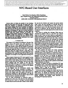
Figure 1. 3D UI generated from a description [Maquil,2004]. Improvise [Zhou & Feiner, 1997] automatically generate coherent visual discourse which refers to a series of connected visual displays. Developers of Improvise developed a visual language that is independent of any graphics platform or package. Automated generation of VRML code has been successfully used in various domains, such as guided tours from physical models [Chittaro et al., 2003], city scenes from city models [Schilling & Zipf, 2003], and graphical art. Another significant manifestation of automated generation of 3D UI is Maquil’s tool [Maquil, 2004] that produces 3D dialog boxes on top of widgets belonging to StudierStube environment (http://www.studierstube.org). Although this system is equipped with an automatic layout facility of the widgets (Fig. 1), the UI specification is rather a description in terms of the StudierStube environment. In addition, no other possibilities exist for obtaining alternative layouts or UIs. The idea of widgets in 3D environments has been the seed of many interesting discussions in mailing lists such as VRML-List, and one of the topics that are usually debated is the question of which should be the standard set of widgets for that kind of environments. The interest in this topic was so high that a working group was formed to study that problem in the context of the VRML language. This working group analyzed two different architectures for VRML-based widgets, being the first a layered approach based on the ideas of P. Isaacs and S. Becker, and the second a component-based approach as suggested by G. Seidman. The first approach considers three layers, the first of them deals with time control and pointer-surface interaction, the second layer is related to the interpretation and control of that interaction (which determines the “feel” of a widget), an the third and last layer adds the geometry (the “look” of a widget). The second architecture considers five basic components, which are the sensors, the internal glue, the geometry, the external glue and, finally, the Virtual Reality User Interfaces (VRUIs, analogous to GUIs). Based on these architectures, different widgets were proposed, and from all of them it is worth to mention the set of G. Seidman, which is quite rich. However, all the pieces of work that result from that group did not finally serve as the basis for a standard toolkit, the group activities ceased and the VRML language continued without the desired standard set of widgets. The lack of a standard set of widgets forces every author to create from scratch the interactive elements that are needed for the project under development, using only those nodes that are specified in the specification of the VRML language. To address this problem and let the author focus on the content of the project, some authoring tools provide a set of VRML prototypes that also includes certain widgets, as for instance interactive buttons. One example of such authoring tools is Internet Scene Assembler (http://www.parallelgraphics.com/products/isa/), developed by ParallelGraphics, which has an extensive library of prototypes which includes button, toggle button, slider, checkbox and text labels, although among the parameters of those prototypes that the author is able to set in order to fit them into his or her project it is not included the geometry of the widgets, which reduces flexibility in their use. The provided subset of widgets is not as rich as those found in 2D development tools, possibly because it may be conceived to serve as a basic set for building Head-Up Display (HUD) interfaces to be used in PC desktop virtual worlds.
Up to this point, we have only described VRML-based projects and tools related to the topic we are concerned. With the development of the third version of that language, X3D, new projects and tools appeared which also address the problem of the widget toolkit. One of those projects is CONTIGRA [Dachselt, Hinz, and Meißner, 2002], whose objectives do not only include the standardization of a repertoire of 3D widgets, but also metaphors and interaction techniques, everything structured in the form a hierarchy. Each component is specified using a XML-base language, which provides all the benefits of using XML technology, and combines X3D language to describe the final appearance and geometry of each 3D widget. Among those widgets, the repertoire includes some of the elements that are used in almost every 2D and 3D application, such as the button and the toggle button, but also other widgets that are only specific to 3D environments, such as the ring menu. The advantage of this set is that it has been designed taking geometry apart from behavior, following an architecture that resembles the ideas proposed by the former VRML Working Group, allowing the author to choose the form that better adjust to the behavior required for his or her project. The disadvantage is that many of the widgets of this hierarchy have not been developed or are not publicly available yet, which limits its adoption as a standard in the field. Besides this, it is not clear enough how a traditional 2D application could be translated to a 3D environment using that set of widgets, bearing in mind that some of the widgets used in 2D applications have not got a direct correspondence with a widget of the CONTIGRA hierarchy. With regard to the toolkits developed for virtual environments based on other languages or libraries different than the VRML97 or X3D, it is worth to cite the work described in [Boyd, 1999], [Larimer, 2003] and [Cuppens, 2004]. The first of them was carried out within the INQUISITIVE project, and involved the development of a library of interaction objects which were implemented using the MAVERIK toolkit, including widgets such as the window, dial and slider. The second of those references describe a system called VIEWL, which implements a windowing system based on Qt and DIVERSE, where windows are represented as polygons that are tangent to the surface of a sphere that surrounds the user. The third one is VRIXML, a XML-based language aimed at developing UIs in virtual worlds, whose authors use to create 2D/3D hybrid interfaces, and for that purpose they elaborated a toolkit based on a subset of the classical 2D widgets. In our work, we would like to have a XML-compliant User Interface Description Language that not only supports the description of a UI, whether 2D or 3D, graphical or virtual, but also the method that can be followed to produce such a UI. From these specifications, different UIs should be produced by rendering and automated generation. In this way, it is possible to simulate in the virtual world the look and feel of the same UI in virtual versions of different platforms, such as PDAs, PCs or even Interactive Walls. In addition, it supports migrating a UI from one platform to another (e.g., 2D to 3D) by visually representing this transition. The next section presents the framework that allows this process.
3
A Reference Framework for User Interfaces
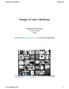
Multi-path UI development is based on the Cameleon Reference Framework [Calvary et al., 2003], which defines UI development steps for multi-context interactive applications. Its simplified version, reproduced in Fig. 2, structures development processes for two contexts of use into four development steps (each development step being able to manipulate any specific artifact of interest as a model or a UI representation): 1. Final UI (FUI): is the operational UI i.e. any UI running on a particular computing platform either by interpretation (e.g., through a Web browser) or by execution (e.g., after compilation of code in an interactive development environment).
2.
3.
4.
Concrete UI (CUI): concretizes an abstract UI for a given context of use into Concrete Interaction Objects (CIOs) [Vanderdonckt & Bodart, 1993] so as to define widgets layout and interface navigation. It abstracts a FUI into a UI definition that is independent of any computing platform. Although a CUI makes explicit the final Look & Feel of a FUI, it is still a mock-up that runs only within a particular environment. A CUI can also be considered as a reification of an AUI at the upper level and an abstraction of the FUI with respect to the platform. For example, in Envir3D [Vanderdonckt et al., 2004], the CUI consists of a description of traditional 2D widgets with mappings to 3D by relying on different mechanisms when such a mapping is possible. Abstract UI (AUI): defines abstract containers and individual components [Limbourg et al., 2004] by grouping subtasks according to various criteria (e.g., task model structural patterns, cognitive load analysis, semantic relationships identification), a navigation scheme between the container and selects abstract individual component for each concept so that they are independent of any modality. An AUI abstracts a CUI into a UI definition that is independent of any modality of interaction (e.g., graphical interaction, vocal interaction, speech synthesis and recognition, video-based interaction, virtual, augmented or mixed reality). An AUI can also be considered as a canonical expression of the rendering of the domain concepts and tasks in a way that is independent from any modality of interaction. An AUI is considered as an abstraction of a CUI with respect to modality. Task & Concepts (T&C): describe the various tasks to be carried out and the domain-oriented concepts as they are required by these tasks to be performed. These objects are considered as instances of classes representing the concepts. Context of use A
Context of use B
n Task & Concepts
r Task & Concepts
o Abstract UI (AUI)
s Abstract UI (AUI)
p Concrete UI (CUI)
tConcrete UI (CUI)
q
u Final UI (FUI)
Final UI (FUI) Reification
Abstraction
Translation
Figure 2. The User Interface Reference Framework. This framework exhibits three types of transformation types: (1,2) Abstraction (respectively, Reification) is a process of eliciting artifacts that are more abstract (respectively, concrete) than the artifacts that serve as input to this process. Abstraction is the opposite of reification. (3) Translation is a process that elicits artifacts intended for a particular context of use from artifacts of a similar development step but aimed at a different context of use. With respect to this framework, multi-path UI development refers to a UI engineering method and tool that enables a designer to (1) start a development activity from any entry point of the reference framework (Fig. 1), (2) get substantial support in the performance of all basic transformation types and their combinations of Fig. 2. In this paper, the four levels will be used for supporting the method where a UI will be mainly described at the CUI level because this level is independent of any computing platform and any particular toolkit. It will be demonstrated that from a same specifications of a CUI, a GUI can be obtained in parallel to a virtualization of this GUI or even another genuine 3D virtual UI. This is why the next section is focusing on the CUI.
4
The Concrete User Interface in UsiXML
In Fig. 2, the last level of abstraction before obtaining a final UI is the CUI level. A description of a CUI can be obtained by successive forward engineering from the T&C level, the AUI level or directly. A CUI is assumed to be described without any reference to any particular computing platform or toolkit of that platform. For this purpose, a CUI model consists of a hierarchical decomposition of CIOs. A Concrete Interaction Object (CIO) is defined as any UI entity that users can perceive such as text, image, animation and/or manipulate such as a push button, a list box, or a check box [Limbourg et al., 2004, Vanderdonckt & Bodart, 1993]. A CIO is characterized by various attributes such as, but not limited to: id, name, icon, content, defaultContent, defaultValue. Since a CIO is independent of any computing platform, we do not know yet which interaction modality is used on that platform. Therefore, each CIO can be sub-typed into sub-CIOs depending on the interaction modality chosen: graphicalCIO for GUIs, auditoryCIO for vocal interfaces, 3DCIO for 3D UIs, etc. In this paper, we focus on graphical CIO since they form the basic elements of a traditional 2D GUI or a 3D, virtual UI. Each graphicalCIO inherits from the above CIO properties and has specific attributes such as: isVisible, isEnabled, fgColor and bgColor to depict foreground and background colors, etc. Each graphicalCIO is then sub-typed into one of the two possible categories (Fig. 3): graphicalContainer for all widgets containing other widgets such as page, window, frame, dialog box, table, box and their related decomposition or graphicalIndividualComponent for all other traditional widgets that are typically found in such containers. A graphicalIndividualComponent cannot be further decomposed. UsiXML supports a series of widgets defined as graphicalIndividualComponents such as: textComponent, videoComponent, imageComponent, imageZone, radioButton, toggleButton, icon, checkbox, item, comboBox, button, tree, menu, menuItem, drawingCanvas, colorPicker, hourPicker, datePicker, filePicker, progressionBar, slider, and cursor. Thanks to this progressive inheritance mechanism, every final elements of the CUI inherits from the upper properties depending on the category they belong to. The properties that have been chosen in UsiXML have been decided because they belong to the intersection of property sets of major toolkits and window managers, such as Windows GDI, Java AWT and Swing, HTML. Of course, only properties of high common interest were kept. In this way, a CIO can be specified independently from the fact that it will be further rendered in HTML, VRML or Java. This quality is often referred to as the property of platform independence. CUI Model
CIO
graphicalCIO
graphicalContainer
graphicalIndividualComponent
Figure 3. Decomposition of a CUI model into concepts.
5
Mapping from UsiXML to VRML97 and X3D
The platform independence then poses the challenge of correctly and appropriately mapping the platform-independent specification (the CUI model) to a platform-specific one (the FUI). Thanks to the UsiXML-based VRML97 and X3D toolkits that have been implemented and that are described in the following sections, it is possible to map interface elements described at the CUI level of UsiXML and those that have been included in the toolkit to allow the generation of a FUI in a VRML97 or X3D-based 3D environment. Without those toolkits, it could not be possible to carry out the mappings, as none of those Web3D standard languages include primitives that can be matched with the CIOs defined in UsiXML. However, the toolkit does not cover everything that is specified in UsiXML, and at the same time introduces new concepts that are not included in UsiXML. Therefore, when attempting to map a CIO from a CUI to a VRML97 or X3D world, several cases practically occurred: 1. Direct mapping between a CIO of the CUI and a VRML97 or X3D primitive. This mapping could be one-to-one (bijection) or one-to-many (composition of objects). As explained before, it is not possible to set a one-to-one mapping as those Web3D languages define basic elements such as shapes and sensors that must be used together to create interactive elements, such as for instance 3D widgets. The new standard X3D does not change this status, even though it includes new 2D geometry nodes that make easier to draw 2D interfaces in a 3D world. 2. New mapping between the CIO and a VRML97 or X3D counterpart. Sometimes, no object exists natively in the X3D language to ensure the mapping. In this case, there is a need to fill this gap by introducing a new widget in the X3D world by appropriate implementation. This is what happens with the CIOs that have been used as a starting point for the toolkit, for each of them there is an element in the toolkit that can be used for their representation in the final interface. However, this correspondence is not complete, as there are some attributes that are defined in the concrete level of UsiXML but that are not used in the 3D world, and there are also other attributes that are added because they are necessary to describe the interface elements in the 3D world, such as those properties that allow the specification of the position and dimension of the widget. 3. No possible mapping. In spite of the implemented toolkit and the elements included in it, there are other CIOs whose counterpart in VRML97 or X3D have not been done yet or it is impossible or difficult to implement it. An example of this is the CIO box defined in the concrete level of UsiXML, which is meant to position the widgets according to some logic constraints. Due to the fact that the implemented toolkit does not include that CIO, it is necessary to perform a transformation that takes the concrete interface as an input and calculate the position and dimensions of each widget in order to output the final interface. Another aspect to take into account when mapping between a concrete interface and its final representation in VRML97 or X3D is that when defining GUI it is being assumed that the final platform will have a screen where the elements will be displayed, and the user will be able to interact with those elements by means of a keyboard and a mouse. When translating those concepts to a virtual world, it is necessary to define which are the counterparts of the screen, the keyboard, and the mouse. With regard to the screen, the implemented toolkit includes a prototype that is called “Screen”, whose function in the toolkit is double. On the one hand, it makes possible to specify a rectangle that represents the rectangular screen of almost every computer display, detailing its dimensions –specifying width and height in
meters, or the diagonal length in inches and the aspect ratio- and its pixel resolution. This prototype accepts a bitmap as a parameter, and has also a sensor that sends out events which contain the coordinates of the pixel at which the user is pointing with his or her pointing device. The second use of this prototype is to serve as a container of elements of a traditional GUI, elements which can be any of those included in the toolkit. For that purpose, the field children is provided in the “Screen” prototype. That field resembles those present in VRML97 and X3D nodes, such as Transform or Group. In fact, the mechanism used in those languages to group nest nodes by means of MFNode field is also the one use in the toolkit to set up the relationships between graphical CIOs. As for the keyboard and mouse, in both VRML97 and X3D specifications it is assumed that the user interacts with the virtual world using a pointing device, and many of the sensors are oriented to the user-world interaction using that device. In this way, the mouse could be mapped with that pointing device that user employs when exploring a VRML97 or X3D virtual world, which indeed in most cases is the mouse of the PC where the virtual world browser is running. The keyboard could also be the PC one, and in that case the only thing needed is a sensor or a set of sensors that detect the key pressing. This is possible with X3D since it offers this kind of sensors, such as StringSensor. But it is impossible to do with VRML97 since it requires the use of nonstandard extensions, such as the KbdSensor from ParallelGraphics. One alternative to using one of those sensors is the introduction of virtual versions of the mouse and the keyboard in the virtual world.
6
Implementation of the VRML97 & X3D toolkits
The architecture of the set of widgets is the same in both VRML97 and X3D versions, and its implementation has been based on the prototyping mechanism which is available in both languages, and also on some of the ideas expressed by the VRML Widget Working Group. This way, for each final widget it has been created a VRML97 and an X3D prototype which are both composed of: an interface based on a set of fields–for setting initial values and also send and receive events-, shapes that represent the appearance and geometry of the widget –customizable through the prototype interface-, the sensors that make possible the interaction between the user and the geometry, internal logic that keep the state of the widget and control the behaviour of it depending on its state, and a set of routes that set up links among shapes, sensors and logic. In order to explain the details of the toolkit, this section will focus on the implementation of one widget, which is the GUIToggleButton. First, as it has been introduced in the previous paragraph, the widget is implemented as a prototype in both VRML97 and X3D versions. The interface of the prototype has been defined from the set of attributes that the toggleButton class has as specified in the concrete level of UsiXML, with some of those attributes being inherited from the cio, graphicalCio and graphicalIndividualCio classes. When adding one attribute from a CIO to a VRML97 or X3D prototype we must adapt the type of the of each attribute to those available in VRML97 and X3D languages. For example, a boolean attribute of a CIO can easily be specified as a SFBool field in VRML97 or X3D. However, whereas the colour of an element is specified as an attribute whose type is string in USIXML, the type of that attribute in the toolkit should be SFColor, which is the most appropriate to describe that property in VRML97 and X3D. The code reproduced in Fig. 4 has been copied from the VRML97 version of the GUIToggleButton prototype: it clearly shows a section containing the mappings to the CIO object, then a section related to the mappings of the graphicalCIO properties, then a section for the graphicalIndividualComponent, and finally the properties of the toggleButton.
PROTO GUIToggleButton [ # USIXML: cio # ... # USIXML: graphicalCio # ... # USIXML: graphicalIndividualComponent # ... # USIXML: toggleButton field SFBool defaultState FALSE # VRML97 GUI Toolkit fields field SFInt32 top 0 field SFInt32 left 0 field SFInt32 width 75 field SFInt32 height 25 exposedField MFNode label [ ] eventOut eventIn eventOut
SFTime SFBool SFBool
touchTime set_state state_changed
eventIn eventIn eventIn eventIn eventOut eventOut eventOut eventOut
SFInt32 SFInt32 SFInt32 SFInt32 SFInt32 SFInt32 SFInt32 SFInt32
set_top set_left set_width set_height top_changed left_changed width_changed height_changed
Figure 4. Definition of a UsiXML toggleButton in VRML97. Due to space reasons and in order to focus the discussion on a few fields, some of the sections of the interface have been cut out. More precisely, it has been cut all the fields that are derived from the cio, graphicalCio and graphicalIndividualCio classes. In contrast, it has been left the attribute defaultState which is defined in the toggleButton class as a property of type boolean and included in the prototype as a SFBool field. Not every attribute that is defined in the concrete level of UsiXML has a meaning in the toolkit, and some other new attributes have to be added to the prototype in order to include some parameters which are related to the final platform, which in this case are virtual worlds created with VRML97 and X3D languages. For example, in the concrete level of UsiXML there are no attributes to specify the position or dimensions of a widget using units such as pixels or meters, because the widgets are laid out on a container using a set of logical relationships. On the contrary, the toolkit that is used to render the final interface in a virtual world requires from each widget its position and dimensions measured in pixels, and for that reason the interface of the GUIToggleButton prototype has four new fields: top, left, width and height. Besides, there are some eventIn fields with same name but for the prefix set_, and some eventOut field with same name too but for the suffix _changed. The internal logic of each prototype handles the incoming events and sends out new events that communicates the changes in the state of the widget. In the case of the X3D version, every prototype parameter is of type inputOutput, which packs three kinds of fields in only one, simplifying the interface by making it more reduce but having the same functionality as the VRML97 version. This reduction in the interface is not possible in the VRML97 specification as fields of type exposedField can not be used in Script nodes. X3D allows Script nodes to include inputOutput, and so the interface of GUIToggleButton is as reproduced in Fig. 5. Apart from the new attributes that define the position and dimensions of the widget, the interface of the GUIToggleButton includes a field named label that is of type MFNode, an attribute that makes possible to assign to any of those widgets another window element that will play the role of button label or box label, as for example a GUITextComponent or a GUIImageComponent element, or even the combination of both of them.
Figure 5. Definition of a UsiXML toggleButton in X3D. There are also some fields that make possible to connect this widget with the rest of the interface and the application, such as touchTime, which is used to cast an event each time the button is pressed, an the field state, which makes it possible to change the state of the button with an incoming event and to communicate the change in the state of the button with and outgoing event (in the VRML97 version there are two fields, set_state and state_changed). The next element of the prototype is a scene graph which includes the shapes that give the widget its appearance and geometry. In a 2D environment, the widget would be drawn using primitives such as points, lines, rectangles, text and images. In VRML97 the shape must be modeled using the nodes that the language offers, such as polylines, polygons, text and textures. In X3D the range of primitives is wider, as it includes new 2D geometry nodes. In both Web3D languages, the geometry of the widget is specified as a hierarchy of transformations whose leaves are the shapes that give to the widget the look it has once rendered in the screen. Another element of each widget is the sensor or sensors that are included in the prototype so that the user can interact with the shapes that are displayed. In the case of the prototype GUIToggleButton, it includes a TouchSensor associated to the button geometry, so that when the user performs the action of touching that geometry with his o her pointing device, the sensor detects the action and cast an event that contains the time when the user touched the button. Besides, this prototype has also two TimeSensors that launch two different animations, one for the case the button is pressed and one for the case the button is released. In both animations, the geometry of the button changes moving along the third dimension, as it would be expected in the real world, instead of using visual tricks as occurs in 2D environments. The event that is cast by the TouchSensor is routed to a Script node that is included in the GUIToggleButton prototype, a node that represents the logic of the widget. This Script node has a set of fields that are matched, by means of IS statements, with some of the fields defined as the interface of the prototype, so that the Script receives the initial values and sets the widget accordingly, changing the geometry and behavior based on the current state of
the widget. Each external event, such as one user action, is then routed to this Script node, executing the corresponding function that will interpret the event and change the state of the widget, sending out events that communicate the changes to other parts of the interface or the application. The last part of the GUIToggleButton prototype, as in any of the rest of the prototypes that are part of this toolkit, is a set of routes, which is the mechanism that is described in the VRML97 and X3D specifications to conduct events from the nodes that cast them to the nodes that receive the events. More precisely, the routes that are included in each prototype have the role of connect the shapes and sensors with the logic of the widget, so that the Script node can rule the behavior of the widget, receiving incoming events and sending out events to the scene graph of the prototype.
7
A case study
In this section, a case study is described as an example running from the topmost level of the reference framework (Fig. 2) until the bottom level, here in VRML97 and X3D. This case of study has been carefully selected for its specification with the USIXML language and later generation of the final interface using the toolkit previously described, and using both VRML97 and X3D versions of it. Thus, as a case of study it has been chosen a music player that uses as source the Internet radio station that the user wants to listen to. This application allows the user to select the music source from a list of available radio stations, reducing the number of items presented in that list by selecting a particular music genre, or introducing some key words for an intelligent search. Once the radio station is selected, the user can play the music that is broadcast by that station, pause or stop the played music at his or her will, and also turn up or down the volume of the music, or even turn it into silence. This example, as it will be seen in the next sections, has been chosen for the rich set of functions that integrates in only one application, which leads also to a rich interface with regard to number and type of elements, which allows us to put into practice all the implemented elements of the USIXML-based VRML97 and X3D toolkit. In the following sections it will be detailed how the USIXML specification of the selected case of study has been carried out, having a look at each model until the final user interface level is reached, then a final user interface is generated using the proposed toolkit in order to deploy the application in a three-dimensional environment build with VRML97 or X3D. 7.1. Task and Concept Model (T&C) The task model is aimed at expressing what will be the user’s actions independently of any implementation of these actions. The high-level task “Listen to radio” is depicted by a cloud since at this level, the task is considered rather abstract (Fig. 6). It is therefore decomposed into a system task “Retrieve list” which will automatically retrieve all radio stations accessible at that time, then passes this information to the radio player display. At this level “Radio player ready”, the user can perform the following actions in any order (“|||” represents concurrency): select a station, play this station, stop it, pause it, increasing or decreasing the volume, and making the player mute or not. All tasks in brackets, e.g. [Play*] mean that they are optional. The star * means that the task can be repeated several times. The “[Play*]” task is a final interactive (user-system icon) task because it cannot be further decomposed, as opposed to the “[Select station*]” task which can be further decomposed into sub-tasks to end up with actions. This task model is saved in UsiXML format to be transformed into an AUI.
Figure 6. Task model of the case study. 7.2. Abstract User Interface Model (AUI) To switch from the task model to a AUI model (Fig. 7), a set of transformations can be applied to automatically generate such an AUI. The results of this generation can then be manually edited in the corresponding editor to refine the specifications. Examples of such transformations involve: for each leaf node task, produce an abstractContainer whose function corresponds to the task type in the task model (e.g., for producing a “Play” control facet in the “Play” container), for each task manipulating an attribute, produce an abstractContainer whose function corresponds to the task action type applied to the domain element (e.g., for producing the “Volume” input facet of the “Volume tuning” container), for each task passing information, produce a container with an input facet related to the user input and a navigation facet to propagate the results of the user input on some other object (e.g., for the “Search” container with “Word” input and navigation in the Station list).
Figure 7. The Abstract User Interface of the case study. 7.3. Concrete Model (CUI) The Abstract UI model only contains a hierarchical decomposition of user’s actions dealing with domain elements. To turn this Abstract UI into a Concrete one, again a series of transformations are applied to the UsiXML specifications for selecting appropriate widgets, for producing the intra-container navigation and extracontainer navigation if appropriate, and for laying out objects depending on constraints imposed by the ordering of sub-tasks within a same level of task decomposition in the task model (Fig. 6). This results into UsiXML specifications at the Concrete UI level which can be opened and edited in an appropriate editor, such as GrafiXML (Fig. 8).
Figure 8. The Concrete User Interface of the case study. Within this editor, the individual components such as buttons, list box, drop-down list box, check box are produced within their appropriate container if any, but no assumption is made on how these components will be in turn reified concretized into dedicated widgets belonging to a particular computing platform and toolkit. The main area of Fig. 8 contains the rendering of the CUI and its left pane displays the current values of each component’s properties. Each property can be edited by direct manipulation of the corresponding component or by alphanumeric editing of the values. Again, everything is saved in UsiXML. 7.4. Final User Interface (FUI) Once the CUI specifications are completed, there is a need to connect each component to the corresponding service. For example, the “retrieve list” computer task in Fig. 6 is mapped onto the definition of a service which calls functions to retrieve this list from the web. Once this step is achieved, the resulting UsiXML specifications can then serve as input for the automated generation of VRML97 and X3D according to the mappings described in Section 5 and on top of the toolkits developed in Section 6. Figures 9 and 10 provide screenshots of the Final User Interface rendered in X3D thanks to the Flux environment. This consists of a 2D GUI rendered in a 3D environment, but with real 3D effects. For instance, when the user presses the “Play” button, the button is really pressed and depressed according to an animation mechanism. When the user selects the drop-down list containing the genres, the list is really scrolled down according to a circular visual effect that is embedded in the underlying toolkit. The same definition of the CUI stored in UsiXML can be equally rendered in VRML97 within the Cortona plug-in for Internet browsers.
software like Cube [Infinite3D, 2004], SphereXP [SphereXP Project Website, 2004] or Looking Glass [SUN Looking Glass Project Website, 2003] are performing. These software exhibit the advantage that nothing should be changed to application to be rendered in 3D, but suffer from the drawback that it is not a real 3D UI since everything is projected into 2D. Now, one can discuss that the components are rendered as 3D widgets in a way that remains similar to the “Look & Feel” of 2D widgets, except that the “Feel” is a genuine 3D behavior. According to this view, this kind of FUI can be interpreted only as a 3D rendering of 2D UIs, even if their specifications are toolkit-independent. The next section examines further this problem.
8
Figure 9. Close view of the final user interface in Flux.
Figure 10. The final user interface rendered in Flux.
Figure 11. The virtual laptop with the FUI rendered in VRML97. Fig. 11 provides a screenshot of this rendering, but augmented with the automatic generation of the computing platform which is simulated, here a laptop. In this case, the user may move, shrink, expand or resize the window on the screen similarly to any classic 2D environment. The big win in this case is that there is no need to change the UsiXML specifications since they are toolkitindependent. They are simply rendered differently depending on the underlying toolkit. The rendering is a genuine 3D rendering of objects as opposed to a 2D projection in a 3D environment as
A Continuum for virtualizing user interfaces
So far, we have shown how to produce UsiXML specifications of a CUI that can be rendered in 3D in two ways, on top of two dedicated toolkits that have been developed for this purpose. The UsiXML specifications do not change whether we want a Java or HTML final user interface (that can be generated by GrafiXML) or a VRML97/X3D one (that can be generated by the system demonstrated here). Our ultimate goal is now to explore how we can expand, refine these specifications to reach a wider spectrum of UIs exhibit various capabilities without changing their specifications, or at least while minimizing the changes of these specifications depending on their type. To introduce and define a wider spectrum of such interfaces while offering different basic or advanced mechanisms and techniques for virtualizing a user interface, we draw some inspiration from Milgram and Kishino [1994] continuum. They defined a continuum of real-to-virtual environments and called the space between Mixed Reality (MR). Mixed Reality includes Augmented Virtuality (AV), in which real world objects are augmented by virtual ones or virtual capabilities that cannot be found in the real world. Augmented Reality (AR) is the other facet of MR in which virtual objects of the virtual world or scene are added to a real environment. A MR environment is assumed to enhance the user’s perception and to improve the intuitive interaction with the real world. Milgram and Kishino’s continuum distributes user interfaces on one dimension ranging from the real environment to the virtual environment by going through the two forms of MR: augmented reality and augmented virtuality. We have extended this continuum by adding a more continuous range of UIs in the virtual part (Fig. 12) since it can be a 2D UI, a 3D rendering of a 2D UI (whether genuine as in our work or simulated), a genuine 3D UI manipulating 3D objects, and so forth. Moreover, a second dimension has been added to represent the degree of immersion that is allowed at each step: low immersion when the user is only looking at the screen (desktop virtual UI) or high when the user is really immersed in the system (CAVE, HMD in a physical space). From the left to the right of Fig. 12, we have respectively: x The true radio player as a physical device. x The same radio player, but augmented information that is superimposed when the user is looking at it with HMD. x A virtual representation of the radio player, but with incorporation of the true physical loudspeakers to directly operate on them through the interface as a remote control. Fig. 13 also depicts an example of such an augmented reality UI. x A purely virtual 3D GUI consisting of a world where virtual objects mimic their real counterparts, but displayed on the user‘s screen. All objects of the UI are virtual and directly operated by direct manipulation of them. x A 3D UI where 3D objects correspond to the tasks (e.g., a sphere to trigger the “Play” function) and the elements (e.g., a cone representing the current volume). Fig. 14 also depicts an example of such a 3D UI where all objects are really spatial.
Degree of immersion Play
P
Play
High
Now playing
V
S
Stop
Stop
Volume:74%
P S
V
Low
Pure reality
Augmented reality
Augmented virtuality
Virtual 3D GUI
Digital 3D GUI
3D rendering of 2D GUI
2D GUI
Virtuality / digitality
Figure 12. An extended continuum of user interfaces from pure reality (left) to the pure digital (right).
Figure 13. An example of augmented virtuality for the case study.
Figure 14. An example of a genuine 3D UI for the case study.
x A 3D rendering of a 2D GUI in a virtual environment, typically a 3D desktop such as Task Gallery, Windows 3DNA. x A classical 2D form-based GUI.
One can observe that on the topmost line of Fig. 12, there is no counterpart with a high degree of immersion for pure reality (since we are already in the real world completely) and no counterpart with a high degree of immersion for 2D GUIs (since we stay in the digital world of the operating system). Our ultimate desire would be that the common parts of these UIs could be factored out and isolated from specific issues belonging to each case. The common parts should be expressed in UsiXML.
On the second line of Fig. 12, corresponding UIs are imagined with a higher degree of immersion than merely on computer. From left to right, we have a series of various UIs: x A tangible UI where physical objects are attached to the player functions (e.g., a physical cube for the “Play” function and a series of graduations for representing the volume of the loudspeakers). A camera captures the movements of the user and interprets them in the same way as she is performing in another virtual UI, except that all operations are performed in the real world, with an effect in the virtual world. x A CAVE-based UI where the previously introduced physical objects are replaced by their virtual counterparts, while keeping the same functions attached. A user equipped with HMD and a glove can directly interact with these objects. x A CAVE-based UI where the radio player is directly represented by its virtual scene. A glove similarly manipulates the user’s hand to mimic the real world’s operations. In this case, the operations are performed in the virtual world as opposed in the real world in the tangible UI. x A CAVE-based UI containing the same 3D objects as in the genuine 3D UI for the case study (as in Fig. 14). x A CAVE-based UI where the classical 2D UIs are projected and manipulated by glove and hand recognition techniques.
9
Conclusion
In this paper, we have presented a set of four models, a method and a suite of software for quickly producing 2D GUIs rendered in a 3D environment with the following benefits: x All steps of the method are stored in UsiXML specifications throughout the development life cycle so that specifications can be refined as the workflow is proceeding. x Once a Concrete UI is obtained, it can initiate an automated generation of the CUI both in VRML97 and in X3D thanks to two toolkits that have been developed for this purpose. x The development of the two toolkits lead to identifying the parts of UsiXML which were possible to map and parts that required further modeling and implementation. This represents an extension of the language that is unique for virtual UIs. x There is a true computer-aided virtualization process of a GUI into a VUI by help of mappings. x Contrarily to other rendering engines, the rendering engines de-
veloped here largely exploit the 3D features of the virtual environment: buttons have a real depth and their animation is implemented as a real translation of the geometry in 3D. The difficulties we have encountered were largely due to establishing the mappings between the CUI and any FUI in VRML and X3D. As X3D only becomes partially supported in tools and plugins, it was sometimes very difficult to test the correctness of the results. In addition, the rendering of a 3D UI in terms of polygons and textures is time consuming and does not always lead to a perfect representation of them in 3D.
Acknowledgements We gratefully acknowledge the support of the SIMILAR network of excellence (www.similar.cc), the European research task force creating human-machine interfaces similar to human-human communication of the European Sixth Framework Programme. José Pascual Molina Massó was also supported by the Spanish CICYT project TIN2004-08000-C03-01 when visiting BCHI. All information regarding UsiXML and software described in this paper are accessible through http://www.usixml.org.
References 3D UI Mailing List Archive. URL: http://people.cs.vt.edu/~bow man/3dui/ 3D Window Manager, URL: http://www.3dwm.org ARJOMANDY, S. AND SMEDLEY, T.J. 2004. Visual Specification of Behaviours in VRML Worlds. In Proceedings of 9th ACM Int. Conf. on 3D Web Technology Web3D’2004 (Monterey, April 58, 2004), ACM Press, New York, 2004, 127–133. BOYD, D. AND SASTRY, L. 1999. Development of the INQUISITIVE interaction toolkit—concept and realisation. In Proc. of Workshop on User Centered Design and Implementation of Virtual Environments UCDIVE’99 (York, September 30th, 1999). CALVARY, G., COUTAZ, J., THEVENIN, D., LIMBOURG, Q., BOUILLON, L., AND VANDERDONCKT, J. 2003. A Unifying Reference Framework for Multi-Target User Interfaces. Interacting with Computers, vol. 15, no. 3, 289–308. CHITTARO, L. AND RANON, R. 2002. Dynamic Generation of Personalized VRML Content: a General Approach and its Application to 3D E-Commerce. In Proc. of 7th Int. Conf. on 3D Web Technology Web3D’2003 (Tempe, February 24-28, 2002). ACM Press, New York, 145–154. CHITTARO, L., RANON, R., AND IERONUTTI, L. 2003. Guiding Visitors of Web3D Worlds through Automatically Generated Tours. In Proc. of 8th Int. Conf. on 3D Web Technology Web3D’2003 (Saint-Malo, March 9-12, 2003). ACM Press, NY, 27–38. Croquet Project Website. URL: http://croquetproject.org/ CUPPENS, E., RAYMAEKERS, CH., AND CONINX, K. 2004. VRIXML: A User Interface Description Language for Virtual Environments. In Proceedings of the ACM AVI’2004 Workshop “Developing User Interfaces with XML: Advances on User Interface Description Languages” UIXML’04 (Gallipoli, May 25, 2004), Luyten, K., Abrams, M., Limbourg, Q., Vanderdonckt, J. (eds.), Gallipoli, 2004, 111–118. DACHSELT, R., HINZ, M. AND MEIßNER, K. 2002. CONTIGRA: An XML-Based Architecture for Component-Oriented 3D Applications. In Proceedings of 7th International Conference on 3D Web Technology Web3D’2002 (Tempe, February 24-28, 2002). ACM Press, New York, 155–163. DACHSELT, R. AND RUKZIO, E. 2003. BEHAVIOR3D: An XMLBased Framework for 3D Graphics Behavior. In Proceedings of 8th Int. Conference on 3D Web Technology Web3D’2003 (SaintMalo, March 9-12, 2003). ACM Press, New York, 101–112. FOLEY, J.D., VAN DAM, A., FEINER. S.K., AND HUGHES, J.F., 1995. Computer Graphics: Principles and Practice in C. AddisonWesley, New York. Infinite-3D and Cube Project Website, 2004. URL:
http://www.infinite-3d.com/ IBM. RealPlaces Design Guide. URL: http://www-3.ibm.com/ ibm/easy/eou_ext.nsf/Publish/580 LARIMER, D., AND BOWMAN, D., 2003. VEWL: A Framework for Building a Windowing Interface in a Virtual Environment. In Proc. of Int. Conf. on Human-Computer Interaction Interact’2003 (Zürich, Sept. 1-5, 2003), IOS Press, 2003, 809–812. LIMBOURG, Q., VANDERDONCKT, J., MICHOTTE, B., BOUILLON, L., LOPEZ, V., USIXML: a Language Supporting Multi-Path Development of User Interfaces. In Proc. of 9th IFIP Working Conference on Engineering for Human-Computer Interaction jointly with 11th Int. Workshop on Design, Specification, and Verification of Interactive Systems EHCI-DSVIS’2004 (Hamburg, July 11-13, 2004). Kluwer Academic Press, Dordrecht, 2004. MAQUIL, V. 2004. Automatic Generation of Graphical User Interfaces in Studierstube, B.Sc. thesis, Institute for Software Technology and Interactive Systems, Vienna Univ. of Technology, https://www.ims.tuwien.ac.at/publication_detail.php?ims_id=140
Microsoft Task Gallery Project Website. URL: http://research. microsoft.com/adapt/TaskGallery/ MILGRAM, P. AND KISHINO, F. 1994. A Taxonomy of MixedReality Visual Displays. In IEICE Transactions on Informations Systems, vol. E77-D, no. 12 MOLINA, J.P., GONZÁLEZ, P., LOZANO, M.D., MONTERO, F., AND LÓPEZ-JAQUERO, V. 2003. Bridging the Gap: Developing 2D and 3D User Interfaces with the IDEAS Methodology. In Proc. of 10th Int. Conf. on Design, Specifications, and Verification of Interactive Systems DSV-IS’2003 (Funchal, June 2003), LNCS Vol. 2844. Springer-Verlag, Berlin, 2003, 303–315. ROBERTS, D., 2000, RealPlaces, 3D Interfaces for Office Applications. In Proc. of Int. Workshop on Tools for Working with Guidelines TFWWG'2000 (Biarritz, October 7-8, 2000). Vanderdonckt, J. and Farenc, Ch. (eds.), Springer-Verlag, London. SCHILLING, A., AND ZIPF, A., 2003. Generation of VRML City Models for Focus Based Tour Animation - Integration, Modeling and Presentation of Heterogeneous Geo-Data Sources. In Proc. of 8th Int. Conf. on 3D Web Technology Web3D’2003 (Saint-Malo, March 9-12, 2003). ACM Press, NY, 39–47. SELIGMANN, D.D., AND FEINER, S. 1991. Automated Generation of Intent-Based 3D Illustrations. In Proceedings of 18th Annual Conference on Computer Graphics and Interactive Techniques SIGGRAPH’91 (Las Vegas, July 28-August 2, 1991), Computer Graphics, vol. 25, no. 4, 123–132. SphereXP Project Website. URL: http://www.hamar.sk/ sphere/ SUN Looking Glass Project Website, 2003. URL: http://www .sun.com/software/looking_glass/index.html VANDERDONCKT, J. AND BODART, F. 1993. Encapsulating Knowledge for Intelligent Automatic Interaction Objects Selection. In Proc. of ACM Conf. on Human Aspects in Computing Systems InterCHI’93 (Amsterdam, April 24-28, 1993). ACM Press, New York, 424–429. VANDERDONCKT, J., BOUILLON, L., CHIEU, C.K. AND TREVISAN, D. 2004. Model-based Design, Generation, and Evaluation of Virtual User Interfaces. In Proceedings of 9th ACM Int. Conf. on 3D Web Technology Web3D’2004 (Monterey, April 5-8, 2004), ACM Press, New York, 2004, 51–60. Web3D Consortium. X3D: The Virtual Reality Modeling Language - International Standard ISO/IEC 14772:200x, URL: http://www.web3D. org/TaskGroups/x3d/specification/ VRML Widgets Working Group Website. URL: http://zing.ncsl. nist.gov/~gseidman/vrml/wwg/ Extensible Markup Language (XML), http://www.w3.org/XML/ XML-Schema, http://www.w3.org/XML/Schema ZHOU, M.X. AND FEINER, S.K. 1997. Top-down Hierarchical Planning of Coherent Visual Discourse. In Proc. of 2nd Int. ACM Conf. of Intelligent User Interfaces IUI'97 (Orlando, January 6-9, 1997). ACM Press, New York, 129–136.