2674
IEEE JOURNAL OF SOLID-STATE CIRCUITS, VOL. 43, NO. 12, DECEMBER 2008
Transmitter Architectures Based on Near-Field Direct Antenna Modulation Aydin Babakhani, Member, IEEE, David B. Rutledge, Fellow, IEEE, and Ali Hajimiri, Member, IEEE
Abstract—A near-field direct antenna modulation (NFDAM) technique is introduced, where the radiated far-field signal is modulated by time-varying changes in the antenna near-field electromagnetic (EM) boundary conditions. This enables the transmitter to send data in a direction-dependent fashion producing a secure communication link. Near-field direct antenna modulation (NFDAM) can be performed by using either switches or varactors. Two fully-integrated proof-of-concept NFDAM transmitters operating at 60 GHz using switches and varactors are demonstrated in silicon proving the feasibility of this approach. Index Terms—BiCMOS, CMOS switch, dielectric lens, dipole, integrated antennas, integrated circuits, modulation, phased-array, reflector, secure communication, silicon Germanium, surface-wave, transmitter, varactor.
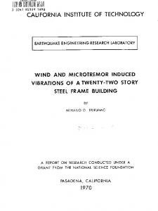
I. INTRODUCTION N THE LATE 1800s and early 1900s, wireless transmission of information started its journey. During this period, inventors such as David E. Hughes, Heinrich Hertz, Nikola Tesla, Guglielmo Marconi, Reginald Fessenden, and Edwin H. Armstrong had to work with long wavelengths due to the lack of high frequency amplifiers [1], [2]. At those wavelengths, the size of an efficient antenna is much larger than the size of the active devices used. The practical issues involved in implementing such large antennas limited the number of effective solutions for designing wireless transceivers. Among these solutions, we can mention the invention of the regenerative, heterodyne, and homodyne receivers [1], [2]. With his invention of the super-heterodyne receiver in 1918, Armstrong introduced the idea of modulating the signal at low frequencies, or baseband, and up-converting it to the radio frequency (RF). Since then, there have been many breakthroughs in related technologies including the invention of the transistor itself in 1947. However, there have been few fundamental changes in transceiver architectures despite the availability of a broad range of supporting technologies; most of today’s high performance systems still use ideas based on the heterodyne or homodyne architectures. Today’s silicon technologies provide transistors with unity-curin excess of 200 GHz, which make rent-gain frequencies it possible to implement mm-wave integrated transceivers on a single chip [3]–[10]. At these frequencies, wavelengths are comparable to the die size and orders of magnitude smaller
I
Manuscript received April 15, 2008; revised June 25, 2008. Current version published December 10, 2008. The authors are with the Department of Electrical Engineering, California Institute of Technology, Pasadena, CA 91125 USA (e-mail:
[email protected];
[email protected];
[email protected]). Digital Object Identifier 10.1109/JSSC.2008.2004864
than those used by Armstrong to implement his first heterodyne receiver (For instance, a simple half-wavelength dipole antenna in vacuum is 2.5 mm long at 60 GHz). Access to faster transistors and the ability to implement antennas on the same die as analog, RF, and digital circuits encourage reevaluation of the classical receiver architectures and exploration of new and fundamentally different architectures. These new architectures should deal with system problems across multiple levels of abstraction, taking full advantage of the greater design space to obtain a more global optimum. Fig. 1 shows the block diagram of a conventional direct-conversion transmitter. In this architecture, the in-phase (I) and quadrature (Q) signals are modulated at baseband and then up-converted to radio frequency (RF). The modulated RF signal goes through a power amplifier (PA) which drives the antenna. It is noteworthy that in this conventional transmitter architecture, the already modulated signal couples to the antenna. As seen in Fig. 1, in a mostly line-of-sight scheme, a receiver sitting in a side lobe of the antenna receives the same information as the receiver located at the antenna’s main beam. The only differences between the receiver data at different directions are the signal power and a time shift. Therefore, given a high-sensitivity receiver it would be possible for a receiver in an unintended direction to eavesdrop on the communication. We will see in the rest of this paper how near-field direct antenna modulation (NFDAM) can be used to overcome the security challenge using a direction-dependent information transmission. In Section II we will discuss the concept of NFDAM. In Section III and IV we discuss the switch-based NFDAM, while in Section V we will investigate the varactor-based version. We will review the circuit level details in Section VI and summarize the measurement results in Section VII. II. CONCEPT OF NEAR-FIELD DIRECT ANTENNA MODULATION In the past, directly modulating the antenna has been used for different purposes in the literatures. For instance, in [11], a microstrip patch antenna is fabricated directly on a silicon-substrate forming a distributed Schottky diode between the patch and the ground plane. In the same paper, a CW microwave carrier is modulated by applying a dc bias control between the patch and the ground. In [12], a patch antenna is integrated with Schottky diodes which are driven by modulating signals. The switches are able to shut off and turn on the antenna’s radiating edges directly to overcome the patch antenna’s bandwidth limitation. In this paper, [12], a patch antenna with a resonance frequency of 2.4 GHz and a 30 MHz bandwidth is used to transmit a digitally modulated signal with 400 MHz bandwidth. It is noteworthy that although the scheme in [12] shares the same
0018-9200/$25.00 © 2008 IEEE Authorized licensed use limited to: CALIFORNIA INSTITUTE OF TECHNOLOGY. Downloaded on January 9, 2009 at 13:24 from IEEE Xplore. Restrictions apply.
BABAKHANI et al.: TRANSMITTER ARCHITECTURES BASED ON NEAR-FIELD DIRECT ANTENNA MODULATION
2675
Fig. 1. Conventional transmitter architecture.
Fig. 3. Modulation after the antenna. Fig. 2. Modulation at baseband.
name (DAM) with our proposed approach, it describes a different system that is different from our proposed one that does not enhance the communication security. In [13] a discrete electronically steerable parasitic array radiator (ESPAR) antenna is used to increase the fluctuation of the channel characteristics. Only the desired transmitter and receiver share the communication channel characteristics and use the fluctuating channel to provide a secret key agreement. Unlike our scheme, the key remains the same for a large number of bits in this approach. In our work, a large number of reflectors with many MOS switches are used to form a near-field direct antenna modulation system by creating a large number of degrees of freedom to be able to generate a broad range of signal constellations with a variety of interesting properties. We will show that, by integrating reflectors and switches in the near-field of an on-chip dipole antenna, we are able to transmit information in a direction dependent fashion with a great deal of flexibility and speed facilitated by the silicon technology. To illustrate the technique of near-field direct antenna modulation (NFDAM), we need to review the characteristics of the conventional systems which are based on modulation at baseband (Fig. 2). In the absence of multipath, any change at the baseband appears in the desired direction as well as the undesired direction (the only difference is the power level and a delay), as illustrated symbolically by the transition from point 1 to point 2. This is because the signal is already modulated before the antenna and because the antenna pattern does not change quickly. The proposed NFDAM technique, illustrated in Fig. 3, is fundamentally different from the one shown in Fig. 2. The NFDAM transmitter utilizes only a locked RF signal source and a PA to drive the antenna. In this scheme we modulate the phase and
amplitude by changing the antenna characteristics and hence its pattern at the symbol transmission rate. As a result, we are able to transmit different signals independently to the desired and the undesired directions, unlike the conventional architectures. In this case, the information is sent to the desired direction and the misinformation is sent to the undesired direction. It is important to realize that we need to change the antenna characteristics (its near- and far-field) at the symbol rate in order to properly modulate the signal. Next, we introduce two alternative techniques to vary the antenna boundary conditions thereby changing the phase and amplitude of the antenna far-field pattern. III. SWITCH-BASED NFDAM Here we will use a basic and somewhat over-simplified model to introduce the concept of near-field direct antenna modulation to provide some basic intuition about it. A toy example of this technique is shown in Fig. 4. On the left side of Fig. 4, we show a dipole antenna with an adjacent reflector in its close proximity. The reflector is composed of two metal pieces connected with an ideal switch. Let us say the main dipole antenna radiates a in the z-direction, normal to the plane signal (bore-sight). Some part of the main signal couples to the adjacent reflector in the near field of the antenna, causing the reflector to scatter a signal in the z direction. By closing the switch, we can change the reflector’s effective length and scattering properties, which cause the reflected signal to have a different phase and amplitude, . In these two cases the far-field signal in the z-direction can be calculated by
Authorized licensed use limited to: CALIFORNIA INSTITUTE OF TECHNOLOGY. Downloaded on January 9, 2009 at 13:24 from IEEE Xplore. Restrictions apply.
(1) (2)
2676
IEEE JOURNAL OF SOLID-STATE CIRCUITS, VOL. 43, NO. 12, DECEMBER 2008
Fig. 4. Signal modulation using switches on the reflectors. (a) Open switch. (b) Closed switch.
Fig. 6. Simulation results of the switch-based NFDAM transmitter (10, 000 points).
Fig. 5. Arbitrary signal modulation.
The real and imaginary parts of the combined signal in the far-field are shown on the signal constellation diagram (Fig. 4). The example above shows how a simple switch can change the characteristics of the reflector and hence perform a crude signal modulation. It is important to realize that the aforementioned illustration is oversimplified. In our system, the reflectors are located in the near-field of the antenna and hence the propagation-based representation used here suffers from not capturing the complete near-field electromagnetic behavior of such a system. In reality these reflectors change the antenna parasitic without necessarily
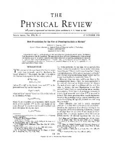
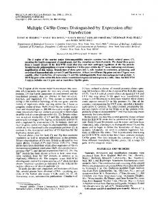
changing the path delay. Changing the antenna parasitic at the near-field of the antenna modulates the far-field radiated signal. Consider a practical system in which more than two constellation points are required in order to transmit the signal at an acceptable bit-rate. The number of points on the constellation diagram can be increased by introducing multiple reflectors, each with multiple switches, as shown in Fig. 5. For total switches, constellation points can be generated. Thus, if we have a sufficiently large number of switches, it is possible to generate a very large number of constellation points. This is illustrated in Fig. 6, where 10,000 random switching combinations are simulated and real and imaginary parts of the induced voltage on a receiving dipole antenna located at the far field are plotted. Five reflectors are placed at each side of the antenna and nine ideal switches are placed on each reflector, resulting in 90 switches in total. Based on this simulation, it is possible to cover all of the four quadrants on the signal constellation diagram.
Authorized licensed use limited to: CALIFORNIA INSTITUTE OF TECHNOLOGY. Downloaded on January 9, 2009 at 13:24 from IEEE Xplore. Restrictions apply.
BABAKHANI et al.: TRANSMITTER ARCHITECTURES BASED ON NEAR-FIELD DIRECT ANTENNA MODULATION
2677
Fig. 7. Communication security. (a) Desired direction. (b) Undesired direction.
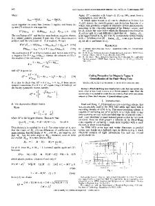
Simulation results show that the coverage of the signal constellation diagram depends on the performance of the switches. For example, by using switches with off-impedance of 70 instead of ideal switches, it is only possible to cover almost one quadrant in the signal constellation diagram. It is also important to carefully choose the switching combinations to minimize the impedance variation at the input of the antenna. Based on the simulation results, if we are willing to tolerate 1.5 dB variation in power gain, 2 dBm variation in delivered power, and 3% variation in power added efficiency of the PA, we are still able to cover one quadrant by using real switches (maximum impedance of 70 ). It should be noted that only the carrier signal goes through the PA, so there is no need to design a broadband PA. A locked oscillator generates an unmodulated sinusoidal signal that drives the PA. As a result, this system is capable of transmitting broadband information while using a narrowband PA. This system also can utilize highly efficient switching PA in transmission of constant and non-constant envelope-modulated signals. In a silicon implementation of the switch-based NFDAM scheme, the switches can be implemented using small-feature size MOS transistors. 1) Secure Communication Link: As mentioned earlier, one of the unique characteristics of this system is its ability to transmit independent signals in different directions, as symbolically depicted in Fig. 7. To see how this is achieved, assume a set of switching combinations has been found which generates a 16 QAM at the bore-sight (Fig. 7(a)). If we look at the modulation points in a direction different than the bore-sight (Fig. 7(b)), we will see that the constellation points are translated from their original locations to seemingly random locations, causing a scrambled set of points on the signal constellation diagram. This happens because the scattering properties of the reflectors and hence the phase and amplitude of the reflected signal vary with angle. The scrambling property prevents undesired receivers from properly demodulating the signal. At larger angles, some of these constellation points move to adjacent compartments (Fig. 8) and introduce error. Fig. 8 shows the simulated error rate versus angle in the E-plane (parallel to dipole) and the H-plane (normal to dipole) of an
on-chip dipole antenna. In this simulation, 210 equally spaced constellation points at the bore-sight are selected and viewed at different angles on the E- and H-planes of the antenna. On the H-plane, the error rate rises rapidly and reaches 50% at offset angles of 2–3 degrees. On the E-plane, the error rate reaches 50% at offset angles of 6–7 degrees off from the bore-sight. Receivers located at angles 1 can completely recover the modulated signal without any error in the absence of noise and other channel non-idealities. In other words, receivers located within the information beam-width of the antenna can properly recover the signal. Thus, it is necessary to define the information beam-width in addition to the power beam-width for such systems. The radiation pattern beam-width represents the power directionality of the beam while the information beam-width refers to the information directionality of the beam. 2) Redundancy and Added Security: It was mentioned that by adding each switch the total number of the switching combinations for switches). combinations is doubled ( In our switch-based NFDAM transmitter prototype design, we have ten reflectors each with nine switches, totaling switches. This results in combinations. Obviously, it is not necessary to use all of these combinations, but this large number of combinations creates so much redundancy that can be utilized in a productive way. It is possible to generate a desired phase and amplitude in a given direction using so many different switch combinations. For a large enough number of combinations, it is possible to find different switch combinations that produce the same point in the desired direction while generating widely scattered points in other directions (Fig. 9). This property of the system allows the transmission of a set of pre-defined modulation points in a desired direction while simultaneously randomly changing the pattern of the constellation points in the undesired directions, thus making it even more challenging for unintended receivers to find a one-to-one mapping between the received signal at the desired direction and the undesired directions. 3) Spectral Control: In most communication transmitters, not only should one adhere to the specifications on the transmitted signal in the frequency band of interest, but it is also nec-
Authorized licensed use limited to: CALIFORNIA INSTITUTE OF TECHNOLOGY. Downloaded on January 9, 2009 at 13:24 from IEEE Xplore. Restrictions apply.
2678
IEEE JOURNAL OF SOLID-STATE CIRCUITS, VOL. 43, NO. 12, DECEMBER 2008
Fig. 8. Information beam-width for a modulation with 210 equally spaced constellation points.
Fig. 10. Spectral control.
Fig. 9. Enhancing security by leveraging redundancy.
essary to control the out-of-band EM emission radiated by the antenna. This is often done through spectral control at base band (e.g., via pulse shaping) which needs to be maintained through the transmit chain (including the PA). This requirement generally translates to a tight specification on the linearity of the transmit path, in particular the PA. It is important for any alternative signal modulation scheme to offer an effective method to control this out-of-band emission of the signal. The spectral control requirement can be translated to trajectory control on the I-Q plane of the signals. A very large number in our prototype) allows coverage of of combinations (e.g., most of the constellation points. This full coverage enables the control of out-of-band emissions as illustrated in Fig. 10. Here, instead of directly moving point A to point B on the signal constellation diagram and generating a high level of out-of-band emissions, the desired trajectory can be rendered by transition through the intermediate steps of 1, 2, and 3, thereby reducing unwanted out-of-band emissions. In general, as long as we have enough redundancy to have a good coverage of the signal constellation, it is possible to render any trajectory on the I-Q plane using multiple intermediate points to achieve spectral control. It is important to realize that this spectral control is achieved at the price of speed. However, for most typical modulation schemes this system offers a very fast switching rate that can be traded with spectral control using this extra degree of freedom offered
in this scheme. This spectral control can be generalized to multiple directions. 4) Phased-Array Configuration: It is noteworthy that each complete NFDAM system including all the reflectors and switches can serve as a single element in a phased-array made of such elements. The phased array allows us to create a narrow power beam-width in addition to the narrow information beam-width achieved via the NFDAM transmitter, as illustrated in Fig. 11. 5) Redundancy and Multiple Beam Transmission: Although not shown with measured results in this paper, the redundancy achieved with a large enough number of switches (enough redundancy), under the right set of EM conditions and switch properties, inspires the idea of concurrently transmitting two independent streams of symbols in two directions at full rate without having to resort to time, frequency, or code division multiple access approaches (Fig. 12). This possibility merits further study. IV. A SWITCH-BASED NFDAM 60 GHZ TRANSMITTER ARCHITECTURE As a proof of concept, a 60 GHz transmitter has been implemented in the IBM 130 nm BiCMOS SiGe (8 HP) process. Fig. 13 shows the block diagram of this transmitter [14]. As shown in this figure, a PA driven by a locked oscillator sends a differential un-modulated sinusoidal signal to a shielded differential transmission line which carries the signal to the on-chip dipole antenna. The dipole has a length of 835 m and a width of 20 m. The differential transmission line uses top metal layer
Authorized licensed use limited to: CALIFORNIA INSTITUTE OF TECHNOLOGY. Downloaded on January 9, 2009 at 13:24 from IEEE Xplore. Restrictions apply.
BABAKHANI et al.: TRANSMITTER ARCHITECTURES BASED ON NEAR-FIELD DIRECT ANTENNA MODULATION
2679
Fig. 11. NFDAM transmitter in a phased-array configuration.
for the signal line, for the bottom ground line, and for the side ground shield. The on-chip dipole antennas and re, , flectors are all implemented on lower metal layers . Five reflectors are placed at each side of the antenna and and 9 switches are placed on each reflector resulting in a total number of 90 switches. The antenna and reflectors occupy an area of 1.3 1.5 mm . As shown in Fig. 13, the baseband data goes through a digital control unit which controls the state of switches. In the switch-based NFDAM architecture, one of the important parameters that needs to be optimized is the distance of the reflectors from the antenna. If the reflectors are placed too far from the main antenna, the reflected signal will be very weak
not being able to change the phase and amplitude of the main signal significantly. On the other hand, if we place reflectors too close to the antenna, the size of the aperture will be very small and the system will not be able to excite a sufficient number of radiation modes to transmit independent information to several directions simultaneously. In this design, the locations of the reflectors and their distance to the main antenna have been optimized. We have implemented a general purpose system capable of generating any arbitrary digitally modulated signal. For a specific modulation, for example 16 QAM, we may not need to use all of the switches. As a part of the system, an optional coarse control unit was implemented as shown in Fig. 14. This optional unit can be
Authorized licensed use limited to: CALIFORNIA INSTITUTE OF TECHNOLOGY. Downloaded on January 9, 2009 at 13:24 from IEEE Xplore. Restrictions apply.
2680
IEEE JOURNAL OF SOLID-STATE CIRCUITS, VOL. 43, NO. 12, DECEMBER 2008
Fig. 12. The idea of multiple beam transmission by using a single transmitter (not simulation results).
Fig. 13. Details of the switch-based NFDAM transmitter architecture.
used as a quadrant selector with control signals and taking . In this mode of operation, switches on the revalues 1 and flectors can be used to generate the constellation points inside each quadrant and the optional coarse control unit can be used to choose the quadrant on the signal constellation diagram. Fig. 15 shows the design of the switch itself. In order to achieve a low on impedance (1–5 ) between the drain and the , the switch source of the switch in its closed state size cannot be small. This results in large gate-drain, , and , capacitances. The NMOS switch used in this gate-source, design has an effective width of 150 m as shown in Fig. 15. To resonate out the switch capacitance and achieve high impedance
, a circular shielded transmission in the open state line behaving as an inductor is placed between the drain and the source of the switch. This transmission line resonates with the open-switch capacitance at 60 GHz resulting in a maximum impedance of 70 . The circular transmission line has a diam, , and eter of 60 m and is implemented on metal layers . One of the main issues which has to be addressed is the transient response of the switches and the reflectors. This determines the speed at which far-field varies and hence determines the maximum symbol modulation rate. The limitation comes from two independent factors. The first one is related to the finite time which the wave needs to travel between the antenna and the reflectors and the second is related to the transient response of the switch. Fig. 16 shows the simulation results of the far-field’s transient response to a change in the switching combination when ideal switches are used. As shown in this figure, the far-field takes less than 200 ps to adapt to a new switching combination. This simulation shows that the effective transient response of the whole system is limited by the transient time of the switch itself, as the switch response is usually longer than 200 ps. By designing a switch with a transient response of about 800 ps we can achieve a symbol rate of better than 1 GS/s. One of the important disadvantages of silicon-based on-chip antennas is the low antenna efficiency. This is a result of two , and subfactors; silicon’s high dielectric constant ). The high level of doping strate’s low resistivity (1–10 required to fabricate active circuits limits the silicon substrate’s resistivity. Silicon’s high dielectric constant and its large substrate thickness (200–300 m) couple most of the dipole output power into substrate-modes in unshielded structures as shown in Fig. 17 [10]. If we use an on-chip ground shield to isolate
Authorized licensed use limited to: CALIFORNIA INSTITUTE OF TECHNOLOGY. Downloaded on January 9, 2009 at 13:24 from IEEE Xplore. Restrictions apply.
BABAKHANI et al.: TRANSMITTER ARCHITECTURES BASED ON NEAR-FIELD DIRECT ANTENNA MODULATION
2681
Fig. 14. Optional coarse control unit.
Fig. 17. Substrate modes [10].
Fig. 15. A 60 GHz resonant NMOS switch.
Fig. 18. Silicon lens.
Fig. 16. Transient response of the far-field.
the on-chip antenna from the lossy substrate, the radiation efficiency will be very small (around 1%). In standard silicon processes the distance between on-chip metal layers rarely exceeds 15 m. A ground layer at this distance, which is much smaller than the wavelength in mm-wave frequencies (2.5 mm wavelength in SiO at 60 GHz), shorts the antenna by introducing a negative image current very close to the antenna and hence reduces both the radiation resistance and the efficiency. On the other hand, if we do not use an on-chip ground shield, the silicon substrate behaves as a dielectric waveguide, generates the substrate modes, and leads the power to the chip edges resulting in
an undesirable pattern. Due to the silicon substrate’s low resistivity, most of the power that couples into substrate modes disappears as heat reducing the overall antenna efficiency [10]. The amount of total power coupled into the substrate modes depends on the substrate’s geometry. If an undoped silicon hemispherical lens (or a dielectric lens with a dielectric constant similar to silicon’s) is attached at the backside of the substrate as shown in Fig. 18, antenna efficiencies up to 10% can be achieved. A silicon lens takes substrate modes and converts them into useful radiated power [10], [14]–[23]. Due to the impedance mismatch between the silicon and the air ( versus ) about 30% of the radiated power will be reflected from the silicon–air boundary, but this problem can be resolved by using a quarter-wavelength matching layer on the boundary of the silicon lens and the air [10], [14]–[23]. In this design a hemispherical silicon lens with a diameter of about 1 inch is used to couple the power to the air.
Authorized licensed use limited to: CALIFORNIA INSTITUTE OF TECHNOLOGY. Downloaded on January 9, 2009 at 13:24 from IEEE Xplore. Restrictions apply.
2682
IEEE JOURNAL OF SOLID-STATE CIRCUITS, VOL. 43, NO. 12, DECEMBER 2008
Fig. 19. Switch-based NFDAM chip micrograph.
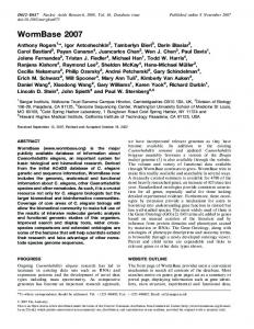
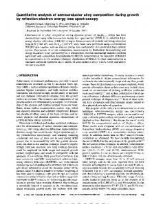
Fig. 19 shows the micrograph of the chip prototype, which is implemented in a 130 nm SiGe BiCMOS process. In addition to the dipole and the reflectors which occupy an area of 1.3 mm 1.5 mm, an optional coarse control unit is designed which includes the baseband amplifiers, the up-converter mixers, and the PA. We have also designed a 60 GHz receiver with on-chip dipole antenna. The receiver is composed of a 60 GHz LNA, down-converter mixers, and baseband amplifiers. The LO signal is generated on-chip by using a V-band VCO. An injection-locked divider and a divider chain are used to divide down the VCO signal by a factor of 1024. V. VARACTOR-BASED NFDAM An alternative to the switch-based NFDAM approach presented earlier is to use a varactor-based approach to change the antenna characteristics and modulate the signal at the far-field. Varactors can be used to change the effective capacitive load on the reflectors. It is noteworthy that the controlling is still done in a digital fashion by switching the capacitance of the varactor and , which are the capacitance values for digital between control values of 0 or 1, respectively. Fig. 20 shows the block diagram of the varactor-based NFDAM system. The differential signal goes through a transmission line and drives the dipole antenna. The varactor-based NFDAM system uses 90 differential varactors on 10 reflectors as shown in Fig. 20. In this design, varactors are implemented by using a series combination of two NMOS transistors as shown , in Figs. 20 and 21. A binary control voltage (` ' ` ' ) is applied to the gate of the NMOS transistors. Depending on the control voltage, gate to drain-source voltage , can be either or . Each of the varactors, NMOS transistor has a size of 3 16 5 m 240 nm. The whole system occupies an area of 2.1 mm 2.4 mm. A micrograph of the varactor-based NFDAM chip is shown in Fig. 22 where it is implemented in the 130 nm IBM 8 HP SiGe BiCMOS process. One of the important parameters that we would like to maximize is the amount of coverage of the signal constellation diagram. In other words, the reflected signals should be strong
enough to change the phase and amplitude of the main signal to cover the four quadrants in the signal constellation diagram without affecting the impedance which the PA sees at the antenna port to maintain a high PA efficiency. To maximize the coverage of the signal constellation diagram, we choose capacand close to the and of the varactor. itances of a varactor is a fixed Usually the ratio of value and is independent of the varactor size. In the process technology used to implement our prototype, the ratio of is around 3. If we choose very small values and then the effective values of the varfor actors’ impedance will be very high in the frequency of GHz, fF and interest. For example at fF result in and . Due to the high impedance of these varactors, the induced current on the reflectors will be negligible compared to the current of the main antenna itself and the reflected signal will be too weak to change the phase and amplitude of the main signal significantly. In other words, the varactors will behave as almost open circuits and and the phase and amplitude in both cases of of the far-field will not significantly change by varying the capacitance of the varactor. The high impedance varactor can make the reflector length much shorter than that of main antenna. This short reflector can still affect the main antenna but this effect is much smaller than that of the case when a reflector with similar length as the antenna is used. When the reflector length and the main antenna length are equal then their resonance frequency are similar and their coupling is strong. and , then Now, if we choose very large values for the effective values of the varactors’ impedance will be very low pF and in the frequency of interest. For example pF result in and at GHz. At these values, varactors behave as short circuits for both values of and and hence the amplitude and phase of far-field will not change by varying the capacitance of the varactors. Fig. 23 shows how signal constellation coverage changes with the values of and . In this simulation we simulated
Authorized licensed use limited to: CALIFORNIA INSTITUTE OF TECHNOLOGY. Downloaded on January 9, 2009 at 13:24 from IEEE Xplore. Restrictions apply.
BABAKHANI et al.: TRANSMITTER ARCHITECTURES BASED ON NEAR-FIELD DIRECT ANTENNA MODULATION
2683
Fig. 20. Varactor-based system’s block diagram (varactor-based NFDAM).
Fig. 22. Varactor-based NFDAM’s chip micrograph. Fig. 21. Design of the varactors and reflectors.
2000 random points, and for each point, for each switching combination, we plotted the real and imaginary parts of the voltage of a dipole antenna located at the far-field. At each point a Matlab program assigns a random binary value for the caof each varactor, , and pacitance plots the real and imaginary parts of the dipole’s voltage located at the bore-sight. As shown in Fig. 23(a), for very small varactor sizes and very large ones the spread of the points on the signal constellation diagram is very limited. As mentioned before, this is because of the fact that very small varactors behave as open circuits and very large ones behave as short circuits at 60 GHz. Fig. 23(b) and (c) show the spread of the constellation fF, fF) and points for varactor sizes ( fF, fF). As shown in Fig. 23(c), with ( fF, fF) it is easily varactor size of (
possible to cover all of the four quadrants with binary controlling of the varactors (` ' ,` ' ). It is important to mention that in the above simulations ideal varactors (infinite Q) are used. Simulations results show that varactors with smaller quality factor reduce the coverage of the signal constellation diagram. Fig. 24 shows the simulation results for varactors’ size fF, fF) with quality factors of 1, 4, of ( and 10. Based on these results, the coverage of the signal constellation diagram is a strong function of the varactors’ quality factor, . In this simulation a silicon lens is used to minimize the substrate modes and efficiently couple the signal to the air. VI. SCHEMATIC OF THE BLOCKS USED IN THE SWITCH-BASED NFDAM TRANSMITTER 1) V-Band Amplifier: Fig. 25 shows the schematic of the V-band amplifier which is composed of three differential stages. Stub-tuning and coupled-wire differential transmission lines are
Authorized licensed use limited to: CALIFORNIA INSTITUTE OF TECHNOLOGY. Downloaded on January 9, 2009 at 13:24 from IEEE Xplore. Restrictions apply.
2684
IEEE JOURNAL OF SOLID-STATE CIRCUITS, VOL. 43, NO. 12, DECEMBER 2008
Fig. 24. Signal constellation coverage for different varactor’s quality factors.
225 m. This transmission line carries the biasing DC voltage to the base nodes of the transistors in the differential pair. At RF frequencies, the line behaves as a stub line and, in conjunction with a 40 m series differential transmission line, provides a power match between the output of the up-converter mixer and the input of the V-band amplifier. In this design, 150 fF MIM capacitors are placed at the output of each differential pair isolating the DC bias of each stage from the following one. The three-stage amplifier provides up to 7 dBm output power. 2) Voltage Controlled Oscillator (VCO): The schematic of the VCO is shown in Fig. 26. A cross-coupled oscillator generates a V-band on-chip LO signal. The oscillation frequency is varied by changing the capacitance of the NMOS varactors which have a size of 15 m as shown in Fig. 26. A differential coupled-wire transmission line is used to behave as an inductor resonating with the parasitic capacitances of the cross-coupled transistors and the capacitance of the NMOS varactors. The important trade-off in designing the cross-coupled oscillator is the trade-off between the phase-noise and the tuning range. The minimum and maximum oscillation frequencies can be calculated by (3) (4)
Fig. 23. Signal constellation coverage for different varactor sizes (ideal varactors).
used for matching purposes. To isolate the differential transmission line from the neighboring blocks, adjacent ground shields as well as bottom ground shields are used [9], [10]. To bias the differential pair, a diode-connected transistor with a series resistor is designed as shown in Fig. 25. The base of this transistor is connected to a differential transmission line with a length of
To achieve a low phase-noise LO, we need to use a large inductor which limits the value of the total capacitance, . Due to the fact that the parasitic capacitance , ultimately depends on the process of the transistor, and not much can be done to minimize it, the only way to reduce the size of the is to reduce the size of the . By making smaller, the tuning range is reduced. To minimize at the collector node of the cross-coupled the effective oscillator, instead of directly connecting the base of one crosscoupled transistor to the collector of another one, a capacitive divider is used, as shown in Fig. 26. This capacitive divider minimizes the total parasitic capacitance seen at the collector node
Authorized licensed use limited to: CALIFORNIA INSTITUTE OF TECHNOLOGY. Downloaded on January 9, 2009 at 13:24 from IEEE Xplore. Restrictions apply.
BABAKHANI et al.: TRANSMITTER ARCHITECTURES BASED ON NEAR-FIELD DIRECT ANTENNA MODULATION
2685
Fig. 25. Schematic of the V-band power amplifier.
Fig. 27. Schematic of the V-band injection locked divider. Fig. 26. Schematic of the V-band VCO.
by minimizing the contribution of the parasitic capacitors connected to the base of the cross-coupled transistors. The capacitive divider also allows a higher voltage swing at the collector node of the transistor by isolating that node from the base node of the transistor. The high voltage swing improves the phase noise of the oscillator. To further reduce the parasitic capacitance at the collector node, the output signal is taken from the base node by connecting the load to the base node instead of the collector node. 91 fF AC-coupling MIM capacitors are used to connect the output of the oscillator to a following amplifier. To bias the VCO, a current source and a diode-connected transistor are used as shown in Fig. 26. 3) Injection-Locked Divider: To divide down the LO signal and lock it to a reference signal, we have used an injectionlocked divider in combination with a digital divider chain. The
divider chain with the injection locked divider provides a dividing ratio of 1024 allowing an off-chip low-frequency signal to be locked with the on-chip LO signal. The VCO, injection locked divider, and divider chain are all implemented on chip. This allows for an off-chip charge-pump/ low-pass filter to be used to lock the oscillator to a lower frequency reference externally using a phased-locked loop. The design of the injection-locked oscillator is similar to that of the VCO but its load is tuned to provide a self-oscillation frequency of around . The LO signal is injected at the current source of the cross-coupled pair, as shown in Fig. 27. A single-ended transmission line with length of 220 m and an ac-coupling capacitor with size of 148 fF are used to maintain a power match between the divider and the preceding stage. The preceding stage is an LO distributor amplifier which is discussed next.
Authorized licensed use limited to: CALIFORNIA INSTITUTE OF TECHNOLOGY. Downloaded on January 9, 2009 at 13:24 from IEEE Xplore. Restrictions apply.
2686
IEEE JOURNAL OF SOLID-STATE CIRCUITS, VOL. 43, NO. 12, DECEMBER 2008
Fig. 28. Schematic of the LO distributor amplifier.
Fig. 29. Up-converter mixer and buffer (optional feature).
4) LO Distributor Amplifier: Several LO distributor amplifiers are used to provide LO signal to the injection-locked divider and up-convertor mixers in the transmitter. The schematic of the LO distributor amplifier is shown in Fig. 28. The LO signal enters through a stub-matching network and is amplified by a cascode differential pair. To distribute the LO signal, the collector current of the input differential pair is divided equally between two identical cascode pairs. These pairs amplify the LO signal and use stub-tuning to efficiently deliver the LO power to the following stages.
Up-Convertor Mixer: As an optional feature in our system, up-convertor mixers are designed and used in the optional coarse control unit. The coarse control unit can be used as a quadrant-selector on the signal constellation diagram. Fig. 29 shows the schematic of the up-convertor mixer. Differential baseband or control signals are connected to the base nodes of the differential pair as shown in Fig. 29. Stub-tuning is used at the RF and LO nodes to maintain a power match between the mixer and the adjacent blocks. To amplify the signal at the output of the mixer, a differential cascode buffer amplifier is
Authorized licensed use limited to: CALIFORNIA INSTITUTE OF TECHNOLOGY. Downloaded on January 9, 2009 at 13:24 from IEEE Xplore. Restrictions apply.
BABAKHANI et al.: TRANSMITTER ARCHITECTURES BASED ON NEAR-FIELD DIRECT ANTENNA MODULATION
2687
Fig. 30. Measurement setup.
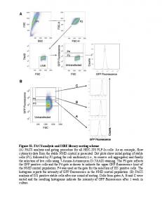
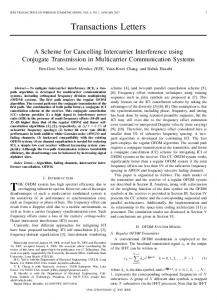
designed as shown in Fig. 29. A 320 m differential transmission line and 148 fF MIM ac-coupling capacitors are used to match the output of the mixer to the input of the buffer. VII. MEASUREMENT RESULTS A block diagram of the measurement setup is shown in Fig. 30. In the first measurement, the on-chip transmitter is disconnected (with laser trimming) from the antenna-reflectors combination and the electromagnetic structure itself is tested using an Agilent N5250A network analyzer. A LabView program [24] controls the state of the switches (switch-based NFDAM) and varactors (varactor-based NFDAM) through a data acquisition card. The data acquisition card sends the digital stream to the on-chip digital control unit and this unit programs the switches and the varactors. After sending the desired data streams and programming the chip, the LabView program communicates with the network analyzer through a GPIB card. One of the ports of the network analyzer sends the V-band signal through a 1.85 mm cable and connectors to the on-chip antenna and the other port uses a standard horn antenna at the receiving side to accurately measure the phase and amplitude . of the By changing the switching combinations in the switch-based NFDAM chip, we can accurately measure the variation in the and plot the real and imaginary phase and amplitude of the on the signal constellation diagram as shown in parts of the in Fig. 31. In this figure, we have measured the variations of two different directions with an angular separation of approximately 90 for the same set of switching combinations. We have measured about 2000 randomly chosen switching combinations and selected the ones which result in 20 equally spaced constellation points in the desired direction. As shown in Fig. 31, the signal constellation points are completely scrambled in the undesired direction, proving the functionality of our system. To have a better look at the constellation points, we have used vertical color-coding to separate these 20 points into several
Fig. 31. Measured constellation points of the switch-based NFDAM chip. In this measurement only the switches are used.
groups. This color-coding, and also the numbering of the constellation points, help us to better understand the scrambling nature of the system. A picture of the measurement setup is shown in Fig. 32. The optional quadrant-selector unit in conjunction with the reflector switching is used to cover the four quadrants on the signal constellation diagram. Fig. 33 shows the measurement results of the full coverage of the four quadrants. We have verified the repeatability of -parameter measurement in several different ways. In one case, we have kept sending a fixed set of switching combinations for one thousand times. This measurement, which was performed over the course of 10 hours, gave us an estimation of error in the -parameter measurement. This error which is much smaller than the distance of two adjacent points in Fig. 33, includes the effects of temperature change, supply voltage noise, and other inaccuracies. To measure the output power of the transmitter and characterize its linearity, the antenna is disconnected from the PA. A 1.85 mm coaxial wafer probe, an Agilent V-band power sensor (V8684A), and an Agilent V-band power (E4418B) meter are
Authorized licensed use limited to: CALIFORNIA INSTITUTE OF TECHNOLOGY. Downloaded on January 9, 2009 at 13:24 from IEEE Xplore. Restrictions apply.
2688
IEEE JOURNAL OF SOLID-STATE CIRCUITS, VOL. 43, NO. 12, DECEMBER 2008
Fig. 32. Picture of the measurement setup.
Fig. 34. Conversion gain and pout versus input power. Fig. 33. Measurement results of the four-quadrant coverage of the signal constellation space using the optional quadrant-selector and switches (switch-based NFDAM chip).
used to measure the output power of the transmitter. The input signal is generated by an Agilent signal source (E8257D) and applied to the input of the transmitter through a wafer probe. Fig. 34 shows the measured output power and gain versus the input power of the transmitter. A transmitter output power of 7 dBm, a small-signal gain of 33dB, and a saturated gain of 25 dB are achieved. In order to measure the VCO performance, a GSG test pad connecting to an on-chip LO signal is designed and used. An Agilent spectrum analyzer (E4448A) and a SpacekLabs off-chip down-convertor (GE-590) are used to measure the phase-noise and tuning range of the VCO. A phase-noise of 100 dBc at 10 MHz offset and a tuning range of more than 2.5 GHz are achieved in the measurement. To measure the performance of the varactor-based NFDAM chip, a setup similar to Fig. 30 is used. Fig. 35 shows the measured constellation points at the received antenna. In this measurement, the LabView program changes the pattern of the varactors by generating about 1400 random combinations and plots
Fig. 35. Measured constellation points in varactor-based NFDAM chip.
the real and imaginary parts of measured by the Agilent N5250A network analyzer. This measurement proves the functionality of the varactor-based NFDAM system. Compared to resonant switches, varactors do not require the circular transmission line to resonate their parasitic elements
Authorized licensed use limited to: CALIFORNIA INSTITUTE OF TECHNOLOGY. Downloaded on January 9, 2009 at 13:24 from IEEE Xplore. Restrictions apply.
BABAKHANI et al.: TRANSMITTER ARCHITECTURES BASED ON NEAR-FIELD DIRECT ANTENNA MODULATION
2689
Fig. 36. Comparison of two boundary value EM problems.
and hence occupy a smaller area. In the varactor-based sysratio and the quality tems, the maximum achievable factor of the varactors are two main factors which determine the coverage of the signal constellation diagram while in the switchbased systems, the off and on impedances determine the coverage of the signal constellation diagram. Based on the simulation results, varactors with quality factor of 10 and ratio of 3 can generate larger spread on the signal constellation diagram than that of switches with off impedance of 300 and on impedance of 3 . In the technology process used in our design, the quality factor of varators was around 3 which significantly reduced the coverage of the signal constellation diagram as shown in Fig. 35. VIII. CONCLUSION In this paper, the technique of near-field antenna modulation (NFDAM) is introduced. Two different methods for implementing NFDAM systems are presented. The transmitter architectures based on NFDAM technique are capable of transmitting direction-dependent data and hence enhancing the security of the communication link. To support the idea, two 60 GHz proof-of-concept chips, one based on switches and the other based on varactors, are implemented and measured. APPENDIX In this Appendix, we explain a simulation technique used in analyzing an electromagnetic structure with many switches or varactors. As mentioned in the discussion related to the NFDAM transmitter architecture, each switching combination defines a
unique boundary condition around the antenna. In the switchbased NFDAM design, 90 switches are used where each asswitching sumes one of two states, on and off. This results in combinations which correspond to unique boundary conditions. While we have not simulated each unique boundary condition (as doing so is not particularly practical or time efficient, and fortunately not necessary), we have simulated to combinations and selected a small set of these combinations to implement an arbitrary digital modulation. If we use conventional techniques to treat each switching combination as an independent EM problem and use EM solvers such as IE3D [25] or HFSS [26] to calculate the far-field for each switching combination, we will not be able to simulate a large enough number of the switching combinations due to the limitation of the simulation time. If we choose Method of Moment (MOM) and use IE3D to simulate the structure, each simulation takes about 5–10 min. To simulate the EM structure using finite element software, such as HFSS, each simulation can take up to 30–60 min. None of these techniques can be used to simulate 1000 points in a time-efficient manner. To simulate these many points, we extracted a circuit model of the whole EM structure and used a combination of circuit software and Matlab code to run each simulation in 10–100 ms. Here we intend to discuss the details of this technique. Fig. 36 shows three different EM configurations. Configuration 1 shows a transmitting antenna, such as a dipole, with an arbitrarily shaped perfect electric conductor (PEC) adjacent to it. We have shown the PEC with a thick black curve. This PEC mimics the reflectors adjacent to the antenna. As shown in Fig. 36, we have disconnected the PEC at a couple of locations and placed terminations with arbitrary impedances at the discontinuities.
Authorized licensed use limited to: CALIFORNIA INSTITUTE OF TECHNOLOGY. Downloaded on January 9, 2009 at 13:24 from IEEE Xplore. Restrictions apply.
2690
Fig. 37.
IEEE JOURNAL OF SOLID-STATE CIRCUITS, VOL. 43, NO. 12, DECEMBER 2008
S -parameter matrix of problem #1.
Fig. 38. Comparison of the optimization techniques.
These impedances are used to model the switches and the varactors. We have also placed a receiving antenna at an arbitrary direction at the far field. This antenna is used to probe the far field at a specific angle. In configuration 2, we change the physical shape of the PEC without changing the termination impedances. To calculate the received voltage of the receiving antenna located at the far-field, we have to run a new EM simulation as we cannot use the EM simulation results of configuration 1. In configuration 3 we vary the values of the termination impedances but keep the physical shape of the PEC unchanged. To calculate the far field in configuration 3, there is no need to run a new EM simulation. In fact the simulation results of configuration 1 can be used to calculate the voltage at the input port of the receiving antenna located at the far field. To do that, we replace the termination impedances in configuration 1 with localized differential ports. We also place localized differential ports at the input ports of the transmitting and receiving antennas. With one receiving antenna, one transterminations on the PEC, indemitting antenna, and pendent ports are defined in configuration 1. Now we can run the -paEM simulation for configuration 1 and extract an
rameter matrix containing all the information required to solve configuration 3. To solve configuration 3 we use the -parameter matrix of configuration 1 but change impedance values of the terminations in the circuit model (Fig. 37). A Matlab code extracts the -parameter data from an EM solver, changes the termination impedances or conductances, and computes the far field by calculating the voltage at the terminal of the receiving antenna. From Fig. 37, we can write the following equations: (5)
(6)
In (5) and (6), ports and Also
represent the current values of the represent the voltage values of the ports. represent the conductance of the termina-
Authorized licensed use limited to: CALIFORNIA INSTITUTE OF TECHNOLOGY. Downloaded on January 9, 2009 at 13:24 from IEEE Xplore. Restrictions apply.
BABAKHANI et al.: TRANSMITTER ARCHITECTURES BASED ON NEAR-FIELD DIRECT ANTENNA MODULATION
2691
problem. Due to the fact that most of the simulation time is consumed by the EM solver, the circuit-model based scheme runs orders of magnitude faster than that of the conventional method. To highlight the advantage of the above technique we have optimized a simple patch antenna by using these two techniques. Fig. 39 shows a simple patch optimization problem. The edge-fed patch with a ground shield is composed of 9 square metal pieces. We have connected these metal squares by using 12 terminations, as shown in Fig. 39. The optimization goal is to maximize the patch bandwidth by finding optimum impedance values for the terminations. The range of the impedances is chosen based on the practical values of the surface mount inductors and capacitors. Our circuit-model based Matlab code uses golden section search and parabolic interpolation to find an optimal solution for the impedance values of the terminations. Fig. 40 shows the simulation results versus frequency. By using one microprocessor of the patch we have achieved a maximum bandwidth of 210 MHz with simulation time of 85 seconds and 12986 iterations. A conventional optimization technique based on PSO/FDTD uses four processors and achieves a bandwidth of 150 MHz in 16 hours and 200 iterations [27]. This conventional technique optimizes the dimensions of the patch and the location of its coaxial feed point to maximize the bandwidth. This simple comparison proves the power of the circuit-model based technique in optimizing the EM problems.
Fig. 39. Patch optimization problem.
ACKNOWLEDGMENT The authors thank Y.-J. Wang for assistance in designing the digital blocks. They also appreciate the support of the Lee Center for Advanced Networking, DARPA’s trusted foundry program, and valuable help from J. Bardin, E. Keehr, and J. Yoo. The technical support for CAD tools from Cadence Design Systems, Agilent Technologies, Zeland Software Inc., and Ansoft Corporation is also appreciated.
Fig. 40. Optimized S11 versus frequency (patch problem).
tions, represents the termination conductance of the receiving represents the impedance seen at the input port antenna, and of the transmitting antenna. is the transposed -parameter matrix of the system and can be calculated from the -parameter data by the following equation: (7) is the nominal impedance (50 ), is the identity In (7), is the inverse of matrix, is the -parameter matrix, and the -parameter matrix. unknowns and equations In (5), (6), and (7), we have and hence have a unique nonzero solution. The unknown pa, and the known ones rameters are are . is the input voltage of the transmitting antenna which is a known parameter. Fig. 38 shows the comparison between the conventional and the circuit-model based optimization techniques in a block flowchart form. In the conventional scheme, one EM simulation is required for each iteration. However, in the circuit-model-based technique, we only need to run a single EM simulation for the whole optimization
REFERENCES [1] Documents of American Broadcasting, F. J. Kahn, Ed., 4th ed. Englewood Cliffs, NJ: Prentice-Hall, 1984. [2] American Broadcasting: A Source Book on the History of Radio and Television, L. W. Lichty and M. C. Topping, Eds.. New York: Hastings House, 1975. [3] X. Guan, H. Hashemi, and A. Hajimiri, “A fully integrated 24- GHz eight-element phased-array receiver in silicon,” IEEE J. Solid-State Circuits, vol. 39, no. 12, pp. 2311–2320, Dec. 2004. [4] H. Hashemi, X. Guan, A. Komijani, and A. Hajimiri, “A 24-GHz SiGe phased-array receiver-LO phase shifting approach,” IEEE Trans. Microw. Theory Tech., vol. 53, no. 2, pp. 614–626, Feb. 2005. [5] A. Natarajan, A. Komijani, and A. Hajimiri, “A fully integrated 24-GHz phased-array transmitter in CMOS,” IEEE J. Solid-State Circuits, vol. 40, no. 12, pp. 2502–2514, Dec. 2005. [6] B. A. Floyd, S. K. Reynolds, U. R. Pfeiffer, T. Zwick, T. Beukema, and B. Gaucher, “SiGe bipolar transceiver circuits operating at 60 GHz,” IEEE J. Solid-State Circuits, vol. 40, no. 1, pp. 156–167, Jan. 2005. [7] B. Razavi, “A 60-GHz CMOS receiver front-end,” IEEE J. Solid-State Circuits, vol. 41, no. 1, pp. 17–22, Jan. 2005. [8] C. H. Doan, S. Emami, A. M. Niknejad, and R. W. Brodersen, “Millimeter-wave CMOS design,” IEEE J. Solid-State Circuits, vol. 40, no. 1, pp. 144–155, Jan. 2005. [9] A. Natarajan, A. Komijani, X. Guan, A. Babakhani, and A. Hajimiri, “A 77 GHz phased array transmitter with local LO-path phase-shifting in silicon,” IEEE J. Solid-State Circuits, vol. 41, no. 12, pp. 2807–2819, Dec. 2006.
Authorized licensed use limited to: CALIFORNIA INSTITUTE OF TECHNOLOGY. Downloaded on January 9, 2009 at 13:24 from IEEE Xplore. Restrictions apply.
2692
[10] A. Babakhani, X. Guan, A. Komijani, A. Natarajan, and A. Hajimiri, “A 77 GHz phased array transceiver with on chip dipole antennas: Receiver and on-chip antennas,” IEEE J. Solid-State Circuits, vol. 41, no. 12, pp. 2795–2806, Dec. 2006. [11] V. F. Fusco and Q. Chen, “Direct-signal modulation using a silicon minostrip patch antenna,” IEEE Trans. Antennas Propagat., vol. 47, no. 6, pp. 1025–1028, Jun. 1999. [12] W. Yao and Y. Wang, “Direct antenna modulation—a promise for ultra-wideband (UWB) transmitting,” in 2004 IEEE MTT-S Int. Microwave Symp. Dig., Jun. 6–11, 2004, vol. 2, pp. 1273–1276. [13] T. Aono, K. Higuchi, T. Ohira, B. Komiyama, and H. Sasaoka, “Wireless secret key generation exploiting reactance-domain scalar response of multipath fading channels,” IEEE Trans. Antennas Propagat., vol. 53, no. 11, pp. 3776–3784, Nov. 2005. [14] A. Babakhani, D. B. Rutledge, and A. Hajimiri, “A near-field modulation technique using antenna reflector switching,” in IEEE ISSCC Dig. Tech. Papers, Feb. 2008, pp. 188–189. [15] D. B. Rutledge et al., “Integrated-circuit antennas,” in Infrared and Millimeter-Waves. New York: Academic, 1983, pp. 1–90. [16] N. Engheta and C. H. Papas, Radio Sci., vol. 17, pp. 1557–1566, 1982. [17] H. Kogelnik, “Theory of dielectric waveguides,” in Integrated Optics, T. Tamir, Ed. New York: Springer-Verlag, ch. 2. [18] N. G. Alexopoulos, P. B. Katehi, and D. B. Rutledge, “Substrate optimization for integrated circuit antennas,” IEEE Trans. Microw. Theory Tech., vol. 83, no. 7, pp. 550–557, Jul. 1983. [19] B. Chantraine-Barès, R. Sauleau, L. L. Coq, and K. Mahdjoubi, “A new accurate design method for millimeter-wave homogeneous dielectric substrate lens antennas of arbitrary shape,” IEEE Trans. Antennas Propagat., vol. 53, no. 3, pp. 1069–1082, Mar. 2005. [20] D. F. Filipovic, G. P. Gauthier, S. Raman, and G. M. Rebeiz, “Off axis properties of silicon and quartz dielectric lens antennas,” IEEE Trans. Antennas Propagat., vol. 45, no. 5, pp. 760–766, May 1997. [21] T. Nagatsuma et al., “Millimeter-wave photonic integrated circuit technologies for high-speed wireless communications applications,” in IEEE ISSCC Dig. Tech. Papers, Feb. 2004, pp. 448–449. [22] M. J. M. van derVorst, P. J. I. de Maagt, and M. H. A. J. Herben, “Effect of internal reflections on the radiation properties and input admittance of integrated lens antennas,” IEEE Trans. Microw. Theory Tech., vol. 47, no. 9, pp. 1696–1704, Sep. 1999. [23] P. Focardi, W. R. McGrath, and A. Neto, “Design guidelines for terahertz mixers and detectors,” in Infrared and Millimeter Waves and 13th Int. Conf. Terahertz Electronics, Sep. 19–23, 2005, vol. 2, pp. 624–625. [24] Labview 8.6. National Instruments Corp. [Online]. Available: http:// www.ni.com/labview/ [25] IE3D. Zeland Software. [Online]. Available: http://www.zeland.com/ [26] HFSS, 3D Full-wave Electromagnetic Field Simulation. Ansoft, LLC. [Online]. Available: http://www.ansoft.com/hfss/ [27] N. Jin and Y. Rahmat-Samii, “Parallel particle swarm optimization and finite-difference time-domain (PSO/FDTD) algorithm for multiband and wide-band patch antenna designs,” IEEE Trans. Antennas Propagat., vol. 53, no. 11, pp. 3459–3468, Nov. 2005. Aydin Babakhani (S’03–M’08) received the B.S. degree in electronics engineering from the Sharif University of Technology, Tehran, Iran, in 2003. He received the M.S. and Ph.D. degrees in electrical engineering from the California Institute of Technology, Pasadena, in 2005 and 2008, respectively. He is currently a Postdoctoral Scholar at the California Institute of Technology. Mr. Babakhani is the Vice Chair of the IEEE Microwave Theory and Techniques Society Metro LA/SFV Joint Sections MTT-S Chapter 17.1. He was the recipient of the Microwave Graduate Fellowship in 2007, the Grand
IEEE JOURNAL OF SOLID-STATE CIRCUITS, VOL. 43, NO. 12, DECEMBER 2008
Prize in the Stanford-Berkeley-Caltech Innovators Challenge in 2006, ISSCC 2005 Analog Devices Inc. Outstanding Student Designer Award, and Caltech Special Institute Fellowship and Atwood Fellowship in 2003. He was also the Gold Medal winner of the National Physics Competition in 1998 and the Gold Medal winner of the 30th International Physics Olympiad in 1999, Padova, Italy.
David B. Rutledge (M’75–SM’89–F’93) is the Chair of the Division of Engineering and Applied Science at the California Institute of Technology, Pasadena, and the Tomiyasu Professor of Electrical Engineering. His research has been in radio transmitters and microwave antennas. He is the author of the textbook Electronics of Radio (Cambridge University Press), and the popular microwave computer-aided-design software package Puff. He is a Fellow of the IEEE, and a winner of the Teaching Award of the Associated Students at Caltech.
Ali Hajimiri (M’99) received the B.S. degree in electronics engineering from the Sharif University of Technology, Tehran, Iran, and the M.S. and Ph.D. degrees in electrical engineering from Stanford University, Stanford, CA, in 1996 and 1998, respectively. He was a Design Engineer with Philips Semiconductors, where he worked on a BiCMOS chipset for GSM and cellular units from 1993 to 1994. In 1995, he was with Sun Microsystems, where he worked on the UltraSPARC microprocessor’s cache RAM design methodology. During the summer of 1997, he was with Lucent Technologies–Bell Labs, Murray Hill, NJ, where he investigated low-phase-noise integrated oscillators. In 1998, he joined the faculty of the California Institute of Technology, Pasadena, where he is a Professor of electrical engineering and the Director of Microelectronics Laboratory. He is a cofounder of Axiom Microdevices Inc. His research interests are high-speed and RF integrated circuits. He is the author of The Design of Low Noise Oscillators (Springer, 1999) and has authored or coauthored more than 100 refereed journal and conference technical articles. He holds more than 30 U.S. and European patents. Dr. Hajimiri is a member of the Technical Program Committee of the IEEE International Solid-State Circuits Conference (ISSCC). He has also served as an Associate Editor of the IEEE JOURNAL OF SOLID-STATE CIRCUITS, an Associate Editor of the IEEE TRANSACTIONS ON CIRCUITS AND SYSTEMS–PART II, a Guest Editor of the IEEE TRANSACTIONS ON MICROWAVE THEORY AND TECHNIQUES, a member of the Technical Program Committees of the International Conference on Computer Aided Design (ICCAD), and the Guest Editorial Board of Transactions of Institute of Electronics, Information and Communication Engineers of Japan (IEICE). Dr. Hajimiri was selected to the top 100 innovators (TR100) list in 2004 and is a Fellow of the Okawa Foundation. He is a Distinguished Lecturer of the IEEE Solid-State and Microwave Societies. He is the recipient of Caltech’s Graduate Students Council Teaching and Mentoring Award as well as Associated Students of Caltech Undergraduate Excellence in Teaching Award. He was the Gold Medal winner of the National Physics Competition and the Bronze Medal winner of the 21st International Physics Olympiad, Groningen, The Netherlands. He was a corecipient of the IEEE JOURNAL OF SOLID-STATE CIRCUITS Best Paper Award of 2004, the ISSCC Jack Kilby Outstanding Paper Award, two times corecipient of CICC’s Best Paper Awards, and a three times winner of the IBM faculty partnership award as well as National Science Foundation CAREER award.
Authorized licensed use limited to: CALIFORNIA INSTITUTE OF TECHNOLOGY. Downloaded on January 9, 2009 at 13:24 from IEEE Xplore. Restrictions apply.