ing manufacture, especially when dealing with free-form parts, such as aerofoils ... domain. Two-dimensional triangulation is then per- formed in R2 and the derived connectivity is applied to ... (b) registration, which establishes correspondence.
509
Triangulation of unordered data using trimmed NURBS computer aided design models M Ristic*, D Brujic and S Handayani Mechanical Engineering Department, Imperial College of Science, Technology and Medicine, London, UK Abstract: Computer aided design (CAD) models of many complex engineering parts, typically in the aerospace and the automotive industries, are de®ned using trimmed NURBS. The shape of the ®nished part can be captured by measuring a suciently large number of points. Triangulation of those points is a frequent requirement in the analysis of that shape as part of the quality assessment and of the product and manufacturing process development. The paper proposes a new method for ecient and robust triangulation of large sets of unordered three-dimensional points, based on the available CAD model. Unlike many other methods, it is not constrained by certain types of measurement distribution or object shapes. Examples involving real engineering parts are presented, with the conclusion that the method was well suited for the perceived applications in engineering manufacture. Keywords: triangulation, trimmed NURBS, CAD, reverse engineering, dimensional inspection, random data 1
INTRODUCTION
Given a set of spatial points that lie on an object surface, triangulation is the process of establishing a correct connectivity structure between the points, such that the resulting triangular mesh is a correct representation of the object shape. The need to perform triangulation arises in many ®elds and it is generally performed for the purposes of: (a) shape modelling, (b) visualization of measured data, especially rendering (shading), (c) interpolation of the measured data involving resampling, usually to produce a regular grid from unordered data, or surface ®tting, (d) simulation, such as that using ®nite element methods. These needs also arise in applications involving engineering manufacture, especially when dealing with free-form parts, such as aerofoils, turbomachinery components, car body panels and others. The nominal computer aided design (CAD) model of such parts is usually de®ned using NURBS (non-uniform rational B-spline), especially trimmed NURBS. The shape of the ®nished
The MS was received on 1 December 1999 and was accepted after revision for publication on 17 January 2000. *Corresponding author: Mechanical Engineering Department, Imperial College of Science, Technology and Medicine, Exhibition Road, London SW7 2BX, UK. SC00200 # IMechE 2000
part may be captured using the conventional coordinate measuring machine (CMM), hand-held digitizers, laser scanners or other available metrology system. The measurement sets in such cases can be very large, sometimes containing more than a million points. Triangulation is often made dicult by the fact that the ordering of the points is not necessarily known, because laser scanners and structured light systems tend to suer from the occlusion problem, while contact systems (such as the CMM) tend to produce unpredictable results in the vicinity of ®ne features [1]. These problems are further complicated by the presence of measurement noise. Under these circumstances, industrial applications require triangulation methods that are robust and computationally ecient. This paper proposes a new method for triangulation of unordered three-dimensional data aimed at applications in engineering manufacture, such as inspection and reverse engineering. It achieves its performance by utilizing the CAD model of the part as an approximation of the actual shape. 2
TRIANGULATION OF UNORDERED THREEDIMENSIONAL DATA
Among the many possible triangulations, Delaunay triangulation [2] is widely considered to provide the `best' triangles as it maximizes the smallest angle and minimizes the largest circumcircle of each triangle. This de®nition strictly applies only in two dimensions, leading Proc Instn Mech Engrs Vol 214 Part B
510
M RISTIC, D BRUJIC AND S HANDAYANI
to an equivalent three-dimensional de®nition involving circumspheres of tetrahedra. In three dimensions, triangulation of a given point cloud can be undertaken through one of the two available approaches, namely the volume-based approach [3, 4], called tetrahedrization, and the surface-based approach [3], which was adopted in the work presented here. Although tetrahedrization algorithms can be quite ecient [4, 5], they are considered to be less suitable because they generate closed volumes, while engineering models mostly involve open surfaces. The principles of three-dimensional surface triangulation were laid out by Boisonant [3], whose method was subsequently adopted by a number of researchers [6]. The approach is to identify a suitable R2 domain which is dieomorphic relative to the object surface, so that the data points are uniquely projected on to that domain. Two-dimensional triangulation is then performed in R2 and the derived connectivity is applied to the three-dimensional data points. In the original method by Boisonant the R2 domain is a plane, derived by ®tting through a neighbourhood of k closest points. After triangulating those k points, the mesh is progressively expanded to include further k points at each step, for which another triangulation plane is employed. The main drawback of this approach is that the data distribution must meet criteria that are in practice dicult to satisfy: 1. The maximal distance between each pair of closest points must be smaller than half the radius of the maximal curvature of the original surface, which means that local point density must be controlled in relation to local curvature. 2. The point set must be isotropic, which means that data mostly arranged in dense scans are degenerate. 3. Point density must be suciently high to ensure that no point on the opposite side of the object is included in the k-neighbourhood, which is dicult to guarantee with thin objects and with high local curvature (e.g. aerofoil shapes). 3
PROPOSED METHOD
(c) two-dimensional triangulation, performed on the corresponding points in the parametric domains of each entity; (d) application of the connectivity structure to the threedimensional data points for each mesh patch; (e) elimination of redundant triangles of each threedimensional mesh patch; (f ) stitching of patches together, if required, in the case of multiple model entities; (g) mesh optimization. The following sections provide the necessary mathematical de®nitions and explain these steps in more detail. 4
TRIMMED NURBS SURFACE DEFINITION
A NURBS surface of degree (k; l) is a bivariate vectorvalued piecewise rational function of the form Pn Pm i0 j 0 Ni;k
uNj;l
vwi;j Pi;j S
u; v Pn Pm ; i0 j 0 Ni;k
uNj;l
vwi;j
u; v 2 0; 1 The fPi;j g form a bidirectional control net, the fwi;j g are the weights and the fNi;k
ug and fNj;l
vg are the nonrational B-spline basis functions de®ned on the knot vectors: U f0; . . . ; 0 ; uk 1 ; . . . ; ur ÿ k ÿ 1 ; 1; . . . ; 1g |{z} |{z} k1
k1
V f0; . . . ; 0 ; ul 1 ; . . . ; us ÿ l ÿ 1 ; 1; . . . ; 1g |{z} |{z} l 1
l 1
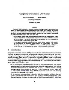
where r n k 1 and s m l 1. A trimmed NURBS surface (Fig. 1) consists of two things: a tensor product of the untrimmed NURBS surface and a set of properly ordered trimming curves lying within the parameter rectangle of the surface [7]. The trimming curves can be of any form, but it is more consistent to represent them as NURBS. Any number M of such curves can be expressed as Cq
t
uq
t; vq
t n X
The proposed triangulation method essentially follows the idea of Boissonant in that it adopts a base surface as the R2 domain on to which the points are projected and two-dimensional triangulation is performed. That base surface is here provided by the trimmed NURBS entities of the CAD model. The steps in the proposed procedure are as follows:
with knot vectors
(a) alignment, if necessary, between the data and the CAD model; (b) registration, which establishes correspondence between the data points and those on the CAD surface entities;
The curves Cq
t are all properly ordered and closed to form outer and inner loops. The CAD model of a part is usually represented by a smooth surface, made by a number of adjacent trimmed NURBS patches and the smooth connection between the
Proc Instn Mech Engrs Vol 214 Part B
i0
Ni;k
tPqi ;
q 1; 2; . . . ; M
Tq f0; . . . ; 0 ; tk 1 ; . . . ; tm ÿ k ÿ 1 ; 1; . . . ; 1g |{z} |{z} k1
k1
SC00200 # IMechE 2000
TRIANGULATION OF UNORDERED DATA USING TRIMMED NURBS CAD MODELS
511
Fig. 1 Single entity trimmed NURBS surface
patches is maintained by overlapping the untrimmed NURBS base surfaces. For the purposes of this work, model geometry was imported using IGES ®les as the standard for geometric data exchange. Since IGES does not support de®nition of patch adjacency, this information was separately derived and stored in an internal modelling data structure. 5
ALIGNMENT
Since the measured points and the CAD model are normally provided relative to dierent coordinate frames, alignment of the two objects is usually necessary in order to guarantee the required dieomorphism. Threedimensional alignment is a non-trivial problem and the adopted solution was based on the modi®ed iterative closest point (ICP) algorithm, as a realization of leastsquares ®tting. As the name suggests, this is an iterative process to minimize the collective model-part distance, where the cost function is F
N X i1
jqi ÿ Rpi ÿ tj2
and t is the translation vector, R is the rotation matrix, pi is the ith measurement point, qi is the closest point on the nominal model and N is the number of measured points. Function minimization is performed using singular value decomposition, to obtain the appropriate geometric transformation that aligns the two objects. The original algorithm in reference [8] was substantially modi®ed by the authors, as reported in reference [9], and its performance was veri®ed against a number of criteria, as reported in reference [10]. The resulting implementation was shown to achieve robustness in the presence of measurement noise and high computational eciency, predominantly through ecient calculation of the closest point on the NURBS entity as the timecritical step. For the purposes of this work, however, the algorithm had to be modi®ed in order to deal SC00200 # IMechE 2000
properly with models de®ned using multiple surface entities.
6
REGISTRATION AND PARAMETERIZATION IN R2
For each measured point, registration establishes its corresponding point on the CAD model and assigns its parametric (u; v) address in R2 . In principle, this may be realized as a by-product of the described ICP alignment procedure, provided that all measured points are used for alignment and that ICP accounts for the fact that surface entities are trimmed. However, it is considerably more ecient if registration is explicitly performed in a separate step. The adopted registration algorithm is an adaptation of the scan-conversion algorithm [11], which was originally developed for ®lling in two-dimensional polygons in basic raster graphics. The pseudo code is given as follows: for each measured point for all trimmed surface entity in the neighbourhood of measured point Find the closest point on the untrimmed base surface. Test this closest point to resolve the point validity in the trimming region. if this closest point is inside the trimming region then This is the true corresponding point. if this closest point is outside the trimming region then Find the closest point to the trimming curve boundaries. Set this closest point as the true corresponding point. Compare the distance to the corresponding point of this entity with that of other entities in the neighbourhood. Proc Instn Mech Engrs Vol 214 Part B
512
M RISTIC, D BRUJIC AND S HANDAYANI
Resolve the corresponding point as the one with the shortest distance to the correct trimmed entity. 7
TRIANGULATION
Based on the (u; v) addresses determined through registration, the required point connectivity structure can be built by triangulation in two dimensions. It is clear that two-dimensional Delaunay triangulation in the (u; v) domain does not guarantee the Delaunay quality of the corresponding three-dimensional mesh in the (x; y; z) domain because of the distortions associated with the domain mapping. This is why three-dimensional mesh smoothing needs to be subsequently applied. However, two-dimensional Delaunay triangulation can still be reasonably expected to lead to a superior three-dimensional mesh than otherwise, requiring a smaller number of computations for the subsequent three-dimensional mesh smoothing. Unconstrained divide and conquer (DC) Delaunay triangulation in the parametric R2 domain was chosen here, due to its computational eciency and reliability. The DC algorithm involves recursive subdivision of the region under consideration into almost equally sized subregions, generation of the connectivity information for each subregion and then merging these results to obtain the ®nal triangulation. This algorithm was adopted from Guibas and Stol® [12], where the main modi®cation was the use of a winged-edge data structure for mesh representation. Among other things, this allows the edges that make up the mesh boundary to be identi®ed, which will be useful later during mesh stitching. The connectivity structure derived in the (u; v) domain is then applied directly to the original three-dimensional data because the point correspondences have been established. The overall algorithm performs triangulation of N random data points in O
N log N time. 8
on a convex domain. In this context they cause two problems. Firstly, they result in a mesh boundary that does not follow well any concavity associated with the outline of the corresponding CAD entity, causing problems in the subsequent stitching step. Secondly, in the case of folded open surfaces, the mesh may not follow well the shape of the object in those regions. The solution to this problem was found in constraint-based triangle elimination according to several criteria. In the present paper implementation of the criteria was based on: (a) edge length, (b) triangle normal direction in relation to the corresponding normal on the CAD model, (c) mesh boundary shape in relation to the trimming curves of the CAD model. Application of the last criterion ensured that mesh patches do not overlap, making the subsequent mesh stitching process relatively straightforward. Stitching then involves identifying the edges that make up the boundaries of adjacent mesh patches. By comparing these edges to the trimming curves of the CAD model a list of adjacent pairs of contours was produced, which were stitched using the triangulation algorithm of Ganapathy and Dennehy [13]. Any small holes that may have been left in the ®nal mesh were readily identi®ed from the winged-edge data structure and ®lled using simple nearest diagonal triangulation. Mesh smoothing is the ®nal processing step which optimizes the triangle shapes. It was eciently implemented through the diagonal edge ¯ipping procedure, which simply examines the two possible diagonals of a quadrilateral composed of a pair of adjacent triangles, in order to choose the one that achieves the smoothest blend of the quadrilateral with its surrounding triangles. The original algorithm proposed by Choi et al. [14] was modi®ed to incorporate some ideas by Oblonsek and Guid [6], allowing small local radii of surface curvature to be accommodated. The algorithm may be summarized by the following pseudo code: for all quadrilaterals do check for sharp feature (normal angles between triangles >0.5 rad) if sharp feature then choose the diagonal using the smoothness criterion due to Choi else choose the diagonal that maximizes the smallest interior angle of the two triangles
MESH IMPROVEMENT IN THREE DIMENSIONS
The described triangulation produces one distinct mesh patch for each surface entity of the nominal CAD model. Any mesh improvement needs to be performed in three dimensions and may involve: (a) elimination of redundant triangles at mesh patch boundaries, (b) stitching of the patches to produce one contiguous mesh, (c) mesh smoothing as the means of achieving the Delaunay quality of the ®nal result. Redundant triangles at the mesh boundaries are a direct result of the fact that any triangulation strictly operates Proc Instn Mech Engrs Vol 214 Part B
9
EXAMPLES
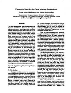
Illustrative triangulation results are provided in Fig. 2, involving a car boot lid. The CAD model comprises 16 trimmed NURBS entities and 3400 randomly distributed measurements were simulated. Distinct mesh patches SC00200 # IMechE 2000
TRIANGULATION OF UNORDERED DATA USING TRIMMED NURBS CAD MODELS
513
(a)
(b)
(c)
Fig. 2 Example of a car boot lid involving 16 entities and 3400 random data points: (a) triangulation for each trimmed NURBS entity, (b) ®nal triangulated mesh, (c) rendered SC00200 # IMechE 2000
Proc Instn Mech Engrs Vol 214 Part B
514
M RISTIC, D BRUJIC AND S HANDAYANI
generated for each entity can be seen in Fig. 2a, while Figs 2b and c show the results after stitching and rendering respectively.
3
10
4
CONCLUSION
The paper proposes a new method for CAD-based triangulation of unordered three-dimensional data, as required by the applications in engineering manufacture, such as inspection. Original solutions for improving the three-dimensional mesh are suggested, based on elimination of redundant triangles, mesh stitching and mesh smoothing. The method was found to be robust and suf®ciently ecient for interactive graphic and on-line visualization applications. As the main requirement for the CAD model is that the measured data are dieomorphic with respect to the corresponding entities, more general applications can also be envisaged when a satisfactory model would be generated speci®cally for this purpose by the user.
5 6
7 8 9
ACKNOWLEDGEMENT
10
This work was supported by funding from the Engineering and Physical Sciences Research Council, Grant GR/2/L15449.
11 12
REFERENCES 13 1 Ristic, M. and Brujic, D. A framework for non-contact measurement and analysis of NURBS surfaces. Int. J. Advd Mfg Technol., 1997, 14, 210±219. 2 De Floriani, L., Falcidieno, B. and Pienovi, C. Delaunaybased representation of surfaces de®ned over arbitrarily
Proc Instn Mech Engrs Vol 214 Part B
14
shaped domains. Computer Vision, Graphics and Image Processing, 1985, 32, 127±140. Boissonant, J. D. Geometric structures for three-dimensional shape representation. ACM Trans. on Graphics, 1984, 3(4), 266±286. Hoppe, H., DeRose, T., Duchamp, T., McDonald, J. and Stuetzle, W. Surface reconstruction from unorganized points. Computer Graphics, 1992, 26(2), 71±78, SIGGRAPH. Cignoni, P., Montani, C. and Scopigno, R. DeWall: a fast divide and conquer Delaunay triangulation algorithm in E d . Computer-Aided Des., 1998, 30(5), 333±341. Oblonsek, C. and Guid, N. A fast surface-based procedure for object reconstruction from 3D scattered points. Computer Vision and Image Understanding, 1998, 69(2), 185±195. Piegl, L. and Richard, A. M. Tessellating trimmed NURBS surfaces. Computer-Aided Des., January 1995, 27(1), 16±26. Besl, P. J. and McKay, N. D. A method for registration of 3-D shapes. IEEE Trans. on Pattern Ann. and Mach. Intell., February 1992, 14(2). Ristic, M. and Brujic, D. Ecient registration of NURBS geometry. Int. J. Image and Vision Computing, 1997, 15, 925±935. Brujic, D. and Ristic, M. Analysis of free form surface registration. Proc. Instn Mech. Engrs, Part B, Journal of Engineering Manufacture, 1997, 211(B8), 605±617. Foley, J. D. Computer Graphics, Principle and Practice, 2nd edition, 1990 (Addison-Wesley, Reading, Massachusetts). Guibas, L. J. and Stol®, J. Primitives for the manipulation of general subdivision and the computation of Voronoi diagrams. ACM Trans. on Graphics, 1985, 4(2), 74±123. Ganapathy, S. and Dennehy, T. G. A new general triangulation method for planar contour. Computer Graphics, July 1982, 16. Choi, B. K., Shin, H. Y., Yoon, Y. I. and Lee, J. W. Triangulation of scattered data in 3D space. Computer-Aided Des., 1988, 20(5), 239±248.
SC00200 # IMechE 2000