3. Interfaces
Poster
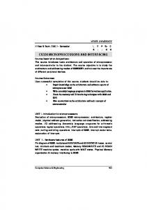
UNIVERSAL MODULAR FLUIDIC AND ELECTRONIC INTERFACING PLATFORM FOR MICROFLUIDIC DEVICES 1 D. Alveringh , R.G.P. Sanders1 , J. Groenesteijn1,2 , T.S.J. Lammerink1 , R.J. Wiegerink1 , and J.C. Lötters1,2 1 MESA+ Institute for Nanotechnology, University of Twente, Enschede, The Netherlands 2 Bronkhorst High-Tech BV, Ruurlo, The Netherlands ABSTRACT A universal modular fluidic and electronic interfacing platform for microfluid devices has been designed, built and tested. The platform supports interfacing chips with up to 8 fluidic and 72 electrical connections. The current module set consists of a high frequency oscillator module, a charge amplifier module, a resonator actuator module and a weather station module. These modules can be used to characterize e.g. pressure sensors, density sensors and Coriolis mass flow sensors. For latter device, the platform with these modules performs approximately 2.5 times better in lower noise than the conventional setup. Besides, chip packaging is two to three times less labor intensive. KEYWORDS Microfluidics, chip interfacing, sensor characterization, micro sensors, micro actuators, flow sensors, pressure sensors, density sensors. INTRODUCTION One challenge in microfluidic sensor and actuator characterization concerns the readout and fluidic interfacing. Usually, a custom packaging method needs to be designed and fabricated for each chip design. For research purposes, sample quantities are limited, therefore packaging is usually done by hand. The Coriolis mass flow sensor from Haneveld et al. [1] for example, has a fluid path and two capacitive readout structures with capacitance changes in the femto farad range. A specific printed circuit board is designed for this chip, as is illustrated in Figure 1a. Magnets for the Lorentz force actuation are adhesively mounted in trenches at both sides (Figure 1b). The chip is adhesively mounted on the copper surface in the center (Figure 1c). Then, the chip is wirebonded to the printed circuit board (Figure 1d) and pin headers are soldered for electrical connections to the measurement equipment (Figure 1e). Finally, fluidic connectors (Swagelok®1/16") are adhesively mounted on the backside of the printed circuit board. This assembled
Conventional assembly
(a)
Novel assembly
(α)
(b)
(c)
(β)
(d)
(γ)
(e)
(f)
Figure 1: Conventional and novel assembly method for the interfacing of microfluidic chips. The conventional assembly consists of adhesively mounting magnets (b), adhesively mounting the chip on the PCB (c), wirebonding the chip to the PCB (d), soldering pin headers (e) and adhesively mounting fluidic connectors (f). The novel assembly consists of adhesively mounting the chip (β) and wirebonding the chip to the PCB (γ).
result can now be electrically and fluidically interfaced, however: • the assembly has been very specific, labor-
The 3rd Conference on MicroFluidic Handling Systems, 4–6 October 2017, Enschede, The Netherlands
106
bolt
chip
wire bond
chip holder board main board
pogo pin
sealing ring
electronic interfacing module coax connector
3D printed fluid block
flat bottom fluid connector
nut
electric power connector Figure 2: Illustration of all components of the interfacing platform. The chip is mounted on a chip holder board. This board is fluidically connected with a 3D printed fluid block to tubing with flat bottom connectors. The chip holder board is connected electrically via pogo pins to the main board. Coax cables connect the main board to electronic interfacing modules.
intensive and riskful work; • other microfluidic devices might have different dimensions or need more electric or fluidic connections, the method is not universal. The complexity of the electronic and fluidic interface is even higher with chips that contain multiple sensors and/or actuators [2, 3, 4, 5]. To gain efficiency, robustness and simplicity, a universal interfacing platform has been designed and built.
2 × 10 and 2 × 4 connectors to improve shielding. The main board has 16 junction gate field-effect transistors (JFET) directly connected to 16 of the 72 signal pins. These transistors can be used as close-to-the-chip amplifiers for capacitive measurements. Connections to the main board, from e.g. modules that will be explained later, can be made using microminiature coaxial (MMCX) connectors. Figure 3 shows the frontside with the chip holder board being placed on the main board.
INTERFACING PLATFORM Figure 2 shows an overview of the platform. Every part of the platform will be briefly described below in this section. The electronic interfacing module set will be described in the next section. Chip holder board The chip holder board (illustrated in Figure 1α) has been inspired by the conventional packaging method, but has multiple improvements. It features: • 8 fluid connections; • 72 electric connections; • 72 grounding connections for shielding. The assembly only consists of adhesively mounting the chip on the chip holder board (Figure 1β) and wirebonding (Figure 1γ). There is no need for the assembly of magnets or soldering the pin headers, since this is implemented in the main board design. Main board The chip holder board can be clamped on the main board with four screws. The electrical connections are realized with pogo pin connectors. For each signal pin, there is a ground pin diagonally alternated in the
Figure 3: Frontside of the main board with a chip holder board being mounted.
Fluidic connector Figure 4 shows the fluidic connector on the main board. This polymer 3D-printed fluidic connector allows for up to 8 fluidic connections to the chip holder board. The fluidic contact is made using o-rings placed in grooves in the fluidic connector. Power board The power board has 8 Peripheral Component Inter-
The 3rd Conference on MicroFluidic Handling Systems, 4–6 October 2017, Enschede, The Netherlands
107
Figure 5: Photograph of the main board with multiple modules.
cillator module, a charge amplifier module, a resonator actuator module and a weater station module.
Figure 4: Backside of the main board with the fluid block and the connectors to the modules.
connect Express (PCIe) connectors to hold the modules and supply power to them. The pinout is not consistent with the PCIe standard; the connectors itself are just used because of its capability to clamp and connect to a PCB directly. Multiple voltages can be applied to the modules via the PCIe connectors, but the default supplied voltage is 10 V. Every module has its own voltage regulator to provide a reliable power source for the electronics. Multiple pins of the PCIe connectors are interconnected to provide a possible bus implementation in the future. ELECTRONIC INTERFACING MODULES These modules can be connected using coaxial cables via MMCX connectors to the main board. The set consists at the time of writing of a high frequency os-
High frequency oscillator This module has two high frequency (mega Hertz range) oscillators. Each oscillator provides a different frequency and has besides the default 5 V square wave output a tuneable amplitude output and an inversed output. The oscillators can be used to provide a carrier signal for e.g. capacitive readout structures. The variable amplitude output can for instance be used for actuation mode cancellation in the capacitive Coriolis mass flow sensor read-out as shown in [6]. Charge amplifier This module has two charge amplifiers for capacitive readout. Each module also has a demodulation circuits, but the charge amplifier can be used solely as well. The demodulation circuits can be synchronized with the high frequency oscillators, which is convenient for the detection of alternating capacitances (e.g. capacitive Coriolis mass flow sensors [1]). Resonator actuator This module consists of a mechanical resonator actuator. The actuator is able to inductively detect the resonance frequency, amplify this signal and actuate the resonator at its resonance frequency. This could, for example, be used for Coriolis mass flow sensors and density sensors [7].
The 3rd Conference on MicroFluidic Handling Systems, 4–6 October 2017, Enschede, The Netherlands
108
Weather station This module consists of a temperature, pressure and humidity sensor. This module has a digital Universal Serial Bus (USB) output. Future modules One planned module has a high voltage amplifier for piezo actuation. Another planned module has a Wheatstone bridge readout circuit. This module will consist of a voltage supply and voltage meter and could be used for the characterization of thermal flow sensors and resistive pressure sensors.
Standard deviation (m°)
PERFORMANCE A Coriolis mass flow sensor has been completely interfaced with all existing modules. The performance of the platform has been tested by measuring the phase shift output of a Coriolis mass flow sensor without flow. The standard deviation has been calculated from the results as a measure for stability. This is done for both the novel platform and the conventional electronics. The phase detection is done using two Stanford Research Systems SR830 lock-in amplifiers. The integration time of the phase detection is varied between 10 ms and 10 s. In Figure 6, it can be seen that the novel platform has a noise level of approximately 2.5 times lower. 32
Conventional Novel
16 8 4 2 1 0.01
0.1 1 Integration time (s)
10
Figure 6: Stability measurement results of the conventional and the novel electronics for lock-in integration times of 10 ms to 10 s.
CONCLUSION The proposed platform provides a time-efficient way to assemble, interface and characterize microfluidic devices. The high number of electric and fluidic connections combined with the modularity of the elec-
tronics enables the characterization of many different types of sensors and/or actuators. Future work will focus on the design of more interface modules, e.g. a high voltage amplifier for piezo actuation purposes and a readout circuit for Wheatstone bridges. ACKNOWLEDGEMENTS This research was supported by the Eurostars Programme through the TIPICAL project (E!8264). REFERENCES [1] J. Haneveld et al., “Modeling, design, fabrication and characterization of a micro Coriolis mass flow sensor,” Journal of Micromechanics and Microengineering, vol. 20, no. 12, p. 125001, 2010. [2] J. C. Lötters et al., “Integrated multi-parameter flow measurement system,” in Proceedings of the 27th IEEE International Conference on Micro Electro Mechanical Systems (MEMS 2014). IEEE, 2014, pp. 975–978. [3] J. Groenesteijn et al., “Single-chip mass flow controller with integrated coriolis flow sensor and proportional control valve,” in Proceedings of the 29th IEEE International Conference on Micro Electro Mechanical Systems (MEMS 2016). IEEE, 2016, pp. 788–791. [4] D. Alveringh et al., “Integrated pressure sensing using capacitive Coriolis mass flow sensors,” Journal of Microelectromechanical Systems, vol. 26, no. 3, pp. 653–661, 2017. [5] D. Alveringh et al., “Resistive pressure sensors integrated with a Coriolis mass flow sensor,” in Proceedings of the 19th International Conference on Solid-State Sensors, Actuators and Microsystems (TRANSDUCERS 2019). IEEE, 2017, pp. 1167– 1170. [6] D. Alveringh et al., “Improved capacitive detection method for Coriolis mass flow sensors enabling range/sensitivity tuning,” Microelectronic engineering, vol. 159, pp. 1–5, 2016. [7] J. Groenesteijn et al., “A compact micro coriolis mass flow sensor with flow bypass for a monopropellant micro propulsion system,” in Proceedings of the 2nd Conference on MicroFluidic Handling Systems, MFHS 2014. Albert-LudwigsUniversität Freiburg, 2014, pp. 21–24. CONTACT * D. Alveringh,
[email protected]
The 3rd Conference on MicroFluidic Handling Systems, 4–6 October 2017, Enschede, The Netherlands
109