well as a wealth of data for training machine learning algorithms for various inference tasks .... untextured segmented 3D model, our basic objective is to transfer the underlying .... S for illustration; (d) depth map corresponding to #b; (e) normal map ..... since groundtruth depth information are obtained for free in the rendering ...
Unsupervised Texture Transfer from Images to Model Collections Tuanfeng Y. Wang1 1
input image
Hao Su2
Qixing Huang3
University College London
Jingwei Huang2 2
Leonidas Guibas2
Stanford University
image-to-shape texture transfer
3
Niloy J. Mitra1
TTIC/UT Austin
shape-to-shape texture transfer
edited original image
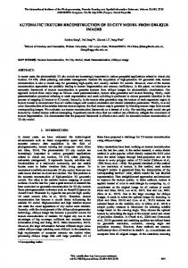
Figure 1: Starting from an input image and a 3D model collection, we propose an unsupervised scalable method for image-to-shape and shape-to-shape texture transfer. The method also allows novel object insertion to the original image (right). The method exploits approximate geometry priors to factorize both geometric and illumination effects. Corresponding original 3D models are shown in blue.
Abstract
1
Large 3D model repositories of common objects are now ubiquitous and are increasingly being used in computer graphics and computer vision for both analysis and synthesis tasks. However, images of objects in the real world have a richness of appearance that these repositories do not capture, largely because most existing 3D models are untextured. In this work we develop an automated pipeline capable of transporting texture information from images of real objects to 3D models of similar objects. This is a challenging problem, as an object’s texture as seen in a photograph is distorted by many factors, including pose, geometry, and illumination. These geometric and photometric distortions must be undone in order to transfer the pure underlying texture to a new object — the 3D model. Instead of using problematic dense correspondences, we factorize the problem into the reconstruction of a set of base textures (materials) and an illumination model for the object in the image. By exploiting the geometry of the similar 3D model, we reconstruct certain reliable texture regions and correct for the illumination, from which a full texture map can be recovered and applied to the model. Our method allows for large-scale unsupervised production of richly textured 3D models directly from image data, providing high quality virtual objects for 3D scene design or photo editing applications, as well as a wealth of data for training machine learning algorithms for various inference tasks in graphics and vision.
Synthesizing realistic 3D objects and scenes remains a central goal of computer graphics. With the growing availability of 2D image and 3D model collections, such as ImageNet [Deng et al. 2009] and ShapeNet [Chang et al. 2015], significant efforts have been made in recent years to jointly harness the complementary nature of the two collection types. Images capture detailed appearance information and provide object context in real world scenes, but lack depth and information about occluded areas. On the other hand, 3D models have rich full-object geometry, but often lack realistic textures needed for high-quality renderings. While significant progress has been made in transferring information across the two collections for pose estimation [Aubry et al. 2014; Hueting et al. 2015], depth estimation [Su et al. 2014a], and image-driven shape segmentation [Kuettel et al. 2012; Guillaumin et al. 2014], the task of marrying 2D image textures with 3D geometry has remained elusive.
Keywords: data-driven graphics, shape analysis, appearance transfer, texture, illumination Concepts: •Computing methodologies ! Image-based rendering; Texturing; Permission to make digital or hard copies of part or all of this work for personal or classroom use is granted without fee provided that copies are not made or distributed for profit or commercial advantage and that copies bear this notice and the full citation on the first page. Copyrights for third-party components of this work must be honored. For all other uses, contact the owner/author(s). c 2016 Copyright held by the owner/author(s). SIGGRAPH ASIA 2016 Technical Papers, Dec 5-8, 2016, Macao, China ISBN: 978-1-4503-4514-9/16/12 DOI: http://dx.doi.org/10.1145/2980179.2982404
Introduction
In this paper we study how to efficiently transfer texture information from 2D images to 3D shapes. Our focus is the simplest version of the problem: given a single 2D image of an object and a partlevel segmented 3D model of a similar but not necessarily identical object, how can we transfer texture information from the image to the model? The eventual goal is to generate a fully textured model whose appearance agrees with the image in the matching view. Given the abundant availability of image data, this immediately enables the generation of large quantities of high-quality 3D models with realistic textures, in an unsupervised setting. Synthesized models can then directly be used in computer graphics content creation applications such as object insertion in images, or be used to provide extensive training data as required by various machine learningbased algorithms for 2D or 3D inference tasks (e.g., classification, depth estimation, shape segmentation, etc.). This problem may seem relatively straightforward, as there are now good tools for aligning images with similar 3D models. The obvious approach would be to try to establish dense correspondences between image and model pairs. However, the imaged real object and the approximating 3D model often exhibit significant difference in shape, both in terms of geometry and topology, making such correspondences difficult to obtain or even define. Furthermore, the
2
(a)
(b)
(c)
Figure 2: The retrieved part-level segmented model (a) for Figure 1, the extracted base texture patches (b), and the recovered orientation field shown as crossfield on the 3D model.
input image provides only partial texture information for the 3D model, as occluded areas are not visible. At a more fundamental level many challenges remain. Firstly, even in visible areas the image texture is distorted by the interaction between the unknown real 3D object geometry and its projection into 2D image space. Furthermore, beyond geometry, complex lighting and shading effects in the image formation process also make it non-trivial to transfer the pure underlying texture from the image to the 3D model – explicit analysis is required to factor out such lighting effects. In other words, we have to decouple the texture distortions arising from object geometry and perspective projection from those due to illumination effects, and correct for both. Our key observation is that images of many man-made objects, even those with complex textures, can be described by appropriately factorized low complexity models, separating texture and illumination information. Specifically, the appearance of an imaged object can be explained in terms of a small number of base texture patches and their orientation in different parts of the object, as well as an illumination model for the object. Both the base textures and the lights are unknown and have to be simultaneously estimated. We demonstrate how to solve the above difficult inverse problem with the help of a 3D model, which only needs to be approximately similar to the imaged object. This (proxy) 3D model provides enough of a geometry base to allow us to decouple geometric distortions from illumination effects, and recover both at the same time, so that their effects on the pure underlying texture can be removed. The retrieved pure base texture can then be used to transfer appearance to other similar 3D models. In Figure 1 for example, given an image I, base texture and illumination are extracted (shown in Figure 2) with geometric guidance from a roughly similar model M1 . The extracted texture is then used to realistically texture model M1 , which in turn helps transfer texture to other models such as M2 , M3 , etc. Finally, we can synthetically add 3D models to the original input image (a teddy in this example). We evaluate our method on three different image-model datasets, namely chairs, tables, and cushions. A user study indicates that users found it difficult to consistently distinguish between the synthesized and real images. In another test, we use the synthesized images to boost training data for machine learning algorithms. In particular, we train deep neural networks for depth estimation and texture-guided image retrieval. For both tasks we observe significant performance improvement by using the enriched shape dataset with more diversified textures. As an application, we show the suitability of our method for novel view synthesis and object insertion. In summary, we formulate and solve the problem of object texture transport from images to 3D models by factorizing out geometric and perspective distortions from illumination effects and compensating for both. We extensively evaluate the performance of the method and demonstrate the utility of the results for different computer graphics and computer vision tasks.
Related Works
Image decomposition. Extracting shape, illumination, and reflectance from shading is a long standing problem in computer graphics and vision. We refer to [Barron and Malik 2015] for a state-of-the-art result on this topic. However, when applying these methods to object images, the results are far below the quality needed in graphics applications, due to the complexity in how different factors that affect the image formation process are interweaved. In this work, we position single point light sources over a sphere around retrieved geometry and render shading samples from an estimated view. These rendered shading samples form the basis of image shading layer. We subsequently apply an optimization based interpolation to recover the coefficient of each shading sample, which successfully decompose the input images without requiring strong assumption on pre-defined priors. Joint image-shape analysis. Our work is also motivated by a recent line of efforts on joint analysis of image and shape collections, which aim at aggregating and propagating the complementary information contained in images and shapes. Most of these prior efforts have focused on transferring shape attributes to images. Representative works in this domain include shape-driven object detection [Aubry et al. 2014], shape-driven object pose estimation [Hueting et al. 2015; Su et al. 2015; Lim et al. 2014], symmetry detection [Fish* et al. 2014], depth reconstruction [Su et al. 2014a; Choy et al. 2016], datadriven image-based modeling [Huang et al. 2015], and image-driven shape segmentation [Wang et al. 2013]. In contrast, transferring image attributes to shapes has received far less attention. In particular, existing works only focus on transferring global-scale attributes such as part segmentations [Wang et al. 2013] and material [Kholgade et al. 2014]. In this work, we focus on transferring texture attributes, which exhibit rich information at both fine and coarse scales. Novel view prediction. Another relevant research topic is predicting the appearance of an object from novel views. In [Su et al. 2014b], Su et al. propose a probabilistic framework for inferring feature representations of unseen views. Such a framework, however, is unsuitable for the synthesis of fine and subtle texture elements. Recently, there have been efforts to predict novel views using convolutional neural networks [Dosovitskiy et al. 2015; Tatarchenko et al. 2015]. However, due to the characteristics of convolutional filters, these methods tend to smooth out local textural details. In contrast, we apply synthesis to generate texture details. Texture synthesis. In contrast to texture mapping, texture synthesis focuses on propagating texture elements across the surface to generate realistic visual appearance. This domain has been studied extensively, and we refer to [Wei et al. 2009] for a survey. Instead of designing new texture synthesis techniques, in this paper we focus on how to adopt existing texture synthesis techniques, i.e., by computing the texture element to be synthesized on each part.
3
Overview
In this paper we focus on clean textured object images, such as product images on the web that are now widely available. We also use publicly available 3D model repositories, such as ShapeNet [Chang et al. 2015]. More formally, our method makes three key assumptions: (i) a clean image of the textured object is available with the background removed, (ii) the texture pattern on the object is homogeneous within object parts and each texture pattern can be built from a texture element of a size that is small when compared to the full part size, and (iii) a similar 3D model is available that is segmented into parts. Given such a product image of a textured object and a similar untextured segmented 3D model, our basic objective is to transfer the underlying textures visible in the image to the corresponding
(1)
(2)
(a)
(3)
(b)
(c)
(d)
(e)
(f)
Figure 3: Pipeline overview. Our system takes an input image (a). A geometrically similar shape is then retrieved (b1). According to the estimated geometry we find large patches on the image (b2) and detect their correspondences (b3). The geometry also helps to factor out shading (c) and reflectance (d), so that base textures (e) are extracted with little distortion and homogeneous lighting. Final texture transfer can be applied to the retrieved model (f).
parts of the model. We also aim to further propagate such texture information to many other related models in the same class. Since textured object images are very common on the web, this enables a novel unsupervised pipeline that can vastly enrich the set of available textured 3D models. Our algorithm deeply exploits the geometry of the 3D model in both correcting illumination artifacts (e.g., shading) on the object and in rectifying the underlying texture information that may have been distorted by the imaging process. We aim to recover the underlying ideal texture directly, undoing the geometric and photometric distortions mentioned above. In this fashion we avoid the need to establish dense image-model correspondences, a difficult task which is not very well defined in our setting since the 3D models and the imaged object are only approximately similar. As a byproduct, our algorithm also builds an illumination model for the object in the image, which can be utilized for image editing tasks.
The rest of the paper is organized as follows: Section 4 describes the core method for extracting appearance (texture and illumination) from image I; transferring this information from image I to shape S; Section 5 describes how to transfer texture information from shape S to other similar models, Section 6 presents evaluation results and finally Section 7 discusses applications.
4
Image ! Shape Texture Transfer
The input to the image to shape texture transfer stage is (i) a given image I with clear background, (ii) a similar 3D object S with partlevel segmentation, and (iii) an estimated camera pose V of I with respect to the coordinate system associated with S. In this paper, we
In our approach (see Figure 3) we seek reliable texture patches in the image which can be geometrically ‘unwrapped’ and photometrically corrected so as to recover the true underlying texture for the corresponding object part. After aligning the 3D model to the object image, we rely on the proxy geometry provided by the 3D model for the texture patch unwrapping. We extract multiple texture patches from the image and attempt to align them based on their periodic structure. This allows us both to select the most reliable patches that best describe the base textures elements to be used, as well as to make decisions about material groups (which texture is to be painted on which shape part). We synthesize a texture image for each material group using the largest extracted reliable texture patches and also estimate the texture orientation (indicated by cross-fields) in each object part. For the illumination correction we again use the 3D model. We sample point light sources over a sphere around the model and generate many grayscale shading images of the model from which we approximate the lighting configuration used in the image (approximated by a discrete distribution over the sampled points). This step extracts the intrinsic image and undoes illumination effects. As the 3D proxy model is not exact, this step is an approximation. However, the extracted illumination is sufficiently correct as preparation for our subsequent texture extraction step. Note that since our goal is to extract a set of base textures, we can only focus on the near planar regions and ignore the regions near boundaries. For the final texture transfer step, we use a global texture synthesis step in the uv texture domain, after some local hole filling. We prefer a global method to avoid spreading artifacts that may still be present in the extracted texture patch. Furthermore, we need to respect the orientation of the texture relative to the object part geometry, as recovered from the image. This is crucial not only for the initial texture transfer to the proxy model, but also for transferring the texture to other 3D models.
Figure 4: Shape retrieval and alignment. Here we show 5 closest results of original and blurred image (to reduce texture effects). We use the closest shape (second column) for further estimation. For each image, we use the estimated view corresponding to the model in the second column.
use the method described in [Huang et al. 2015] to retrieve a similar shape S from a shape collection and to estimate the camera pose V (Figure 4). The remainder of this section describes the details.
4.1
Geometry-guided Patch Extraction
(a) (b) (c) (d)
(e) (f) (g)
We assume that the imaged object in I has a low complexity appearance model, i.e., the object is covered with a repeating texture pattern and imaged under an (unknown) illumination setting. The key challenge is to factor out the projection and illumination artifacts in order to extract a set of simple base textures and an illumination model. We use the geometry information available in the form of shape S to guide both these tasks. First, we detect repeating elements in the input image and then use them to group parts of the input shape S to guide subsequent image decomposition. The repeating elements consist of patches of the input image each of which has a salient regular texture pattern. Extracting such regular texture patterns directly is difficult because the texture may be distorted by the geometry of the captured shape. To address this issue, we use the geometry provided by S to unwrap each texture pattern into a common image plane. As the object in the input image and the shape S are similar, we found that it is sufficient to simply overlay the input image object and the rendered image for depth and normal transfer as explained in the following. Patch initialization. To identify the patches, we uniformly sample a 50 ⇥ 50 grid of points on the input image (Figure 5(f)). From each grid point, we start a region growing step to find the largest square flat region on S centred at that point. The criteria for “flat region” is that within such a region, the normal difference and gradient of depth is less than a certain threshold. In this way we grow a patch around each grid point, extending it from pixel i to pixel j when \i,j (Ni , Nj ) ⌘ , maxi (rDi ) ⇠
(1)
where Ni and Nj denote normals on the mesh S corresponding to pixels i and j, rDi denotes difference in depths on points of S around i, and ⌘ and ⇠ are threshold margins (⌘ = 5 and ⇠ = 3%). We keep all patches that cover more than 400 pixels. We denote
(a)
(b)
(c)
(d)
(e)
(f)
(g)
(h)
(i)
(j)
(k)
(l)
(m)
(n)
(o)
(p)
(q)
(r)
Figure 5: (a): Input image I; (b) retrieved shape S; (c) overlaid I and S for illustration; (d) depth map corresponding to #b; (e) normal map corresponding to #b; (f) uniform grid sampling; (g)-(j): 4 examples of cropped patch from I; (k)-(n) patches directly cropped from I corresponding to highlighted area in (g)-(j); (o)-(r) unwrapped patches into a common image plane to remove perspective distortions.
Figure 6: Patch registration between a pair of unwrapped patches. (a) unwrapped patch; (b) SIFT feature points; (c) Canny edges; (d) distance field of Canny edges; (e-g) examples of registration with red dot denoting corresponding feature point.
these initial patches as {P 1 , P 2 , . . . }, which are allowed to overlap each other. Patch rectification. The appearance of the initial patches may be distorted due to the geometry of the imaged object. Hence, next we use the proxy geometry in the form of S to correct the patches. Specifically, to recover from the distortion of {P 1 , P 2 , . . . }, we unwrap them into a common image plane. We denote the unwrapped patches as {P1 , P2 , . . . }. Unwrapping from P i ! Pi is straightforward since P i is on an almost flat region by construction. While this can be done by a local parameterization approach, we found a much simpler option to be sufficient as explained next. For a patch P i , let the four corners in clockwise direction be {q 1 , q 2 , q 3 , q 4 }. Correspondingly, let the unknown four corners of the unwrapped patch Pi be {q1 , q2 , q3 , q4 }. We simply flatten the patch into a plane by ‘unfolding’ it to a flat configuration while best keeping orginal lengths/areas. We fix q1 to the origin on a 2D plane, set edge q1 q2 to be the X-axis, then unfold 4q 1 q 2 q 4 into 4q1 q2 q4 , and finally 4q 2 q 3 q 4 into 4q2 q3 q4 . We keep the scale ratios of the form kqi qj k/kq i q j k for triangle edges to be fixed for different patches. Since the original patch is flat, this step rarely leads to any foldover. Thus, we obtain rectified texture from different areas of the shape as shown in Figure 5. Patch correspondences. We now establish correspondences across the rectified initial patches to extract a global repeating structure. Moreover, the extracted correspondence across the different patches indicates whether they capture the same texture pattern (or are outliers) and will later help us to group parts based on material (i.e., texture) assignment and to estimate the illumination environment. We start by registering a pair of unwrapped patches Pi and Pj . We first compute SIFT features [Lowe 2004]) on Pi and Pj (we denote the patch with fewer SIFT feature points as Pj ). Let the m-th feature i point of patch Pi be denoted fm . For each such feature point, we have the location (x, y), an orientation r, and a 128-dimensional descriptor d. When registering Pj ! Pi , we simply pick a matching pair of feature points (fki 1 , fkj2 ) and perform a rigid transformation on Pj , where the difference between the feature locations gives the translation and the difference between the feature orientations gives the rotation. Since the patches can overlap, the SIFT features in (fki 1 , fkj2 ) are not helpful for alignment in regions of overlap. Hence, in order to robustly register the two patches, we select the 20 best matches for
each fkj and among these 20 ⇥ |f j | matches, we pick the one with minimum registration energy Er (fki 1 , fkj2 ). This energy gives low values when: (i) the Canny edge of two patches agree, and (ii) the overlap region of the two patches are large. Specifically, Er (fki 1 , fkj2 )
= +
kG(Pi )
the back of the chair is completely occluded, we assign it to the largest texture group, which typically is the one associated with the seat cover. Next, we will synthesize one texture image for each material group based on the notion of a trustable region from the largest associated texture patch.
G(Tk1 k2 (Pj )k2
⇤ A(M (Pi , Tk1 k2 (Pj )),
where Tk1 k2 (·) is the transformation guided from fkj2 ! fki 1 , M (·, ·) is the mask of the union of two patches, A(.) denotes the area of the overlapping region, and G(·) is a distance field of the extracted Canny edge (using OpenCV implementation). In our tests, we set = 0.1 and the distance field is generated by performing a Gaussian blur over Canny edge with kernel size of 15. Figure 6 shows some examples. After two patches are registered with minimum registration energy, we select a 6 ⇥ 6 pixel square around the matched feature points on both Pi and Tk1 k2 (Pj ) denoted as STi and STj . We then determine whether the registration is successful based on the similarity between STi and STj . Since, at this stage, there might be an illumination effect, we simply account for that using a shading intensity ratio k and the similarity between STi and STj is defined by min(kSTi k
k·STj k2 ). Finally, if the similarity value is under a certain threshold, we mark the patch Pi and Pj to be sharing the same texture after a rigid transformation Tk1 k2 . Otherwise, they are marked to be different.
4.2
Material-Guided Patch Grouping
Directly performing part level texture transfer is difficult for two reasons: (i) parts can be totally occluded in image I and (ii) even for the partially visible parts, the texture information extracted from image I could be limited thus preventing high quality texture synthesis. However, for most of the real-world examples, many parts share the same texture (or plain color), thus providing redundancy. We exploit this redundancy to solve the above problems by grouping the original shape parts, with parts within the same group being assigned the same texture. We assume the models to have symmetric parts to be grouped. We group the parts based on texture correspondence, thus producing material-based groups.Specifically, we test all patch pairs (Pi , Pj ) if they are from different groups and merge the two groups if Pi and Pj are registered successfully (as described before). After all patch pairs are examined, some parts can still remain untouched with no associated texture patch. We heuristically complete the material grouping as: (i) for thin parts with no associated textures, we treat them as plain color and use the average pixel value projected on those parts after SIFT flow [Liu et al. 2011] is applied on the image I (see Figure 7); and (ii) for larger parts, we link them into the group with the largest texture patch generated. For example, if a part at
(a)
(b)
(c)
(d)
Figure 7: For the image/shape pair on Figure 5: (a) geometry-based grouping; (b) material-based grouping; (c) calculated SIFT flow from silhouette of image I to silhouette of shape S rendered from the estimated view; (d) apply SIFTflow to image I.
Figure 8: Shading samples using retrieved 3D model geometry. Only a selection of samples are shown.
4.3
Image Decomposition
The patch correspondences can also guide the extraction of illumination from input image I. In order to perform intrinsic image decomposition, we decompose the captured photograph I into reflectance Ir and shading Is , since the render equation tells us I = Ir · Is for each channel of each pixel. In our setting, this implies that for corresponding patches, the Ir component at the corresponding feature points should be the same because they share the same texture location. In other words, when the (unknown) groundtruth shading of this image is factored out from I, Ir for corresponding locations should be the same. Thus we arrive at, X Is := argmin kIr⇤ (li ) Ir⇤ (lj )k, (2) I s⇤
(i,j)2⇧
where Ir⇤ = I/Is⇤ , ⇧ denotes corresponding pairs with matched feature at location li and lj on the image I, and k · k denotes 2-norm of the RGB channels. Note that Is has RGB channels since we found environmental illumination often to be not pure white. In the raw form, Equation 2 is underconstrained. As such, we further regularize Is⇤ with shading priors. We again use the proxy geometry to drastically restrict the degrees of freedom. Specifically, we use the shading image of shape S to approximate Is⇤ . Exploiting the additive nature of illumination, we can decompose Is⇤ into separate parts Is1⇤ + Is2⇤ + . . . . To this end, we sample single point light sources on a sphere around S and render grayscale shading images {Is1 , Is2 , . . . } and approximate Is⇤ by interpolating the sample shading images over the RGB channel. Specifically, we place 100 individual point lights at locations (cos(u) cos(v), cos(u) sin(v), sin(u)) where u = arcsin(1 p 2k 1 ), v = u 100⇡, and k = 1, . . . , 100. For each point light, 100
(a)
(a)
(c)
(b)
(d) (b)
(c)
(d)
Figure 11: (a) Extracted trustable region; (b) hole filling by [Darabi et al. 2012]; (c) texture synthesis by [Efros and Freeman 2001]; (d) directly repeating texture causes visible artifacts.
(e)
(f)
(g)
(h)
Figure 9: (a) Corresponded point pairs; (b) interpolated shading; (c) interpolation coefficients for the different shading samples; (d) shading factorized from the input image I. (e)-(h) shows the selected shading samples.
we render a grayscale shading image as shown in Figure 8. We ignore all fully black shading images as they do not contribute to the decomposition. Note that in this step, we preprocess the shading images to recover the effect of gamma correction. Therefore, via P linear interpolation we have Is⇤ = (cr,g,b · Isk ). Thus, k k=1,..,100
illumination optimization amounts to, X argmin kIr⇤ (li ) {ctk }
regularized as
(i,j)2⇧
P
(cr,g,b k k=1,..,100 P t ck = 1, t k=1,..,100
where Ir⇤ = I/
(3)
Ir⇤ (lj )k,
· Isk ) and the coefficient vector = {r, g, b}.
Instead of providing an intrinsic decomposition with fine detail, Ir⇤ only results in reliable reflectance in large flat areas as shown in Figure 9. This is because shape S is not exactly the same as the object captured in image I, especially around the boundaries and image-model mismatch regions. The above decomposition, however, is still suitable for our goal. First, we mainly care about the texture on the large areas where patch texture could be generated. Second, we do not have to rely on other prior information as in state-of-the-art intrinsic decomposition methods [Bell et al. 2014; Barron and Malik 2015] (see comparison in Section 6). Finally, the recovered coefficients can easily be converted to recreate the illumination by placing light sources with extracted coefficient as intensity for each channel.
4.4
Texture Transfer
Once we factor out the effect of illumination, we focus on reflectance Ir . We regenerate the unwrapped texture patches {P1 , P2 , . . . } based on Ir . As we assume per-part texture to be homogeneous, the largest patch usually captures all necessary texture information. However, it can locally suffer from artifacts (see Figure 10) due to image-shape inconsistency, unexpected patterns, high distortion around boundaries, etc. Hence, directly using the largest patch easily results in unwanted artifacts. In this step, we extract useful texture information from {P1 , P2 , . . . } so that we can synthesize high-quality textures for each material group. To this end, we adopt a simple but effective method: we introduce the notion of trustable region from the largest texture patch of each material group. The criteria for being a trustable region is whether the location texture appears more than once on image Ir . Specifically, for each material group, we perform pairwise patch registration between each patch and the largest patch. After registration, we examine all the corresponding 20 ⇥ 20 pixel patches on STi,j . We mark a region as trustable on STi if the sum of pixel value differences on the 20 ⇥ 20 pixel patch is less than 10%. Texture synthesis. In this step, we generate a texture image for each material group based on the trustable region extracted from the last step. First, we perform hole filling using [Darabi et al. 2012] to regularize the boundary of the trustable region. Then, we simply use [Efros and Freeman 2001] to synthesis a large size texture image. Note that we should preserve the scale of the texture as it is on image I when transferring to shape S. That means we cannot arbitrarily rescale the uv layout when parameterizing each part of S. In order to ensure good quality, we synthesize a large texture image to cover the uv layout instead of directly spatially repeating small texture examples. In our experiment, we found 2048 ⇥ 2048 as a reasonable size with acceptable synthesis time. We apply the method in [Vallet and Lvy 2009] (using Blender’s built-in version called Smart UV Project) on each part of S for uv
(a)
(b)
(c)
(d)
Figure 10: Some examples of artifacts captured by the largest texture patch and the trustworthy region after patch alignment.
(a)
(b)
(c)
Figure 12: (a) Estimated orientation visualized on image I; (b) orientation frame projected on to uv plane; (c) uv-layout after rescaling and rotation.
parameterization. By default, uv coordinates are scaled to [0, 1]. Hence, we rescale the uv coordinates to ensure the number of pixels in texture space covered by the parameterization of the mesh is the same as the number of pixels in image I covered by the mesh when it is projected back to the image plane. We can now transfer orientation of the uv layout to S by following image I. This is straightforward since the correspondence between a patch and the largest patch specifies a common orientation frame. We project the orientations (up and right vector) of all patches onto uv space and pick a dominant up-direction using RANSAC. Specifically, for all the orientations {r1 , r2 , . . . }, we set 20 as threshold and pick the orientation with the most number of inliers. We set the dominant up-direction as the mean orientation of these inliers. We align the dominant up-direction to the up-direction of the texture image. We flip the right direction on uv layout, if necessary based on texture registration score. See Figure 12 for clarification.
5
Shape ! Shape Texture Transfer
In the previous section, we described how to transfer texture from an object in image I to a similar shape S. We now describe how to further diffuse the texture information to other similar 3D models M in the model collection. Note that we assume the model collection to be coaligned [Averkiou et al. 2016]. The main observation is that although the imaged object in I is too different from M to reliably generate base texture elements, it still provides valuable information as to how to orient the (extracted) base textures from I to M . Intuitively, S acts as a bridge to transfer orientation information from image I to the target shape M , while the base textures are obtained based on the I-S analysis. Thus, the main task is to simply map orientation of uv layout. Similar to part-level parameterization of S, we first parameterize each part of shape M . Given a part and its uv layout, for each face, we project the up direction in 3D space at the face center onto the surface and map the projected direction onto 2D uv space. If a face is nearly perpendicular to the up direction, we use the forward direction instead. After that, we use weighted RANSAC to compute the dominant up-direction based on the projected orientations, weighted by face area. This will give us a dominant up-direction for the corresponding parts S⇤ and M⇤ from S and M . By aligning the up-direction from M⇤ to S⇤ , we naturally get the texture orientation. This completes the texture transfer from the image I to the retrieved shape M .
6
Evaluation
In this section, we discuss comparison results with baseline methods, state-of-the-art alternatives, and also report evaluation results assessing the importance of each stage of the pipeline. Code and data is available online1 . Datasets. We tested our pipeline with 70 ‘chair’ images download by searching with keywords chair, fabric chair, wood chair, etc.. As shape collection, we used dataset for ‘chairs’ from the ShapeNet database. We used a sample of 1000 of them for our tests as they already provide enough geometry variance for this task. We also tested with two other classes, ‘cushion’ and ‘table.’
6.1
Result gallery
We show a sample of texture transfer results for 42 images in Figure 15 (please zoom to see the results). For each image, we retrieve the closest shape and transfer texture from the image to shape as 1 http://geometry.cs.ucl.ac.uk/projects/2016/texture
transfer/
Figure 13: Image-to-shape and shape-to-shape texture transfer results for ‘cushion’ and ‘table’ classes.
shown in the diagonal entry. After that, we perform shape-to-shape texture transfer from the closest shape to the other 41 shapes. The images are rendered from a novel view. Images rendered with estimated view are in the supplementary material. For the cushions and tables datasets, we show results with 5 images for each category in Figure 13. We evaluate generality of our approach on different categories (cap, mug, vase, aeroplane) of objects in Figure 14. In this case we select 5 models from ShapeNet for each category.
(a)
(b)
(c)
(d)
Figure 14: Texture transfer results for other categories. First row: input image. Second row: retrieved shape and extracted texture patch. Last row: re-rendered image with our texture transfer output and estimated illumination. Please note that the proxy shapes differ from the input images, such as the brim of the cap, handle of the mug, top of the vase, and aeroplane wings.
6.2
Comparison with baseline methods
Baseline #1: SIFTflow-based projection. One simple baseline method for transferring texture from image to shape is to compute a dense correspondence between the image and a retrieved 3D model and then simply transfer texture information from the image to the projected model. As shown in Figure 7, we use SIFTflow technique to build such a dense correspondence between the silhouette of the image and the silhouette of the shape rendered from the estimated view. After applying SIFTflow, we project the pixels directly onto shape using the estimated dense correspondence. Note the original image is not corrected for shading effect. Figure 16 shows some example results. Baseline #2: Shapenet textures. Another baseline is simply to take the texture information (when present) from the ShapeNet database. Please note that the quality of texture from ShapeNet is very variable. For example, in the chair category, about 50% of the shapes have
Figure 15: Appearance transfer on ‘chair’ dataset. Image-to-shape (diagonal entries) and shape-to-shape appearance transfer results. This is a high resolution figure, please zoom in to view details. The results (3D textured models along with recovered illumination setting) are also available for download as supplementary material.
meaningless textures, i.e., simple color assignment. On the other hand, a handful of the models (about 5 10% come with high-quality texture, probably hand-curated by some professional. User study. We conducted a user study on Amazon Mechanical Turk (AMT) to compare the results of our unsupervised method against the two baseline methods and also real images (product photographs). We tested on 4 datasets: (i) 70 real images; (ii) transfer texture of each such real images to the closest (retrieved) shape using our approach and rendered from the estimated view under estimated illumination; (iii) SIFTflow-based projection from the real images
to the closest (retrieved) shape and rendered using our estimated illumination in a slightly rotated view from our estimation; and (iv) for each retrieved closest shape, we apply the associated texture from ShapeNet and render from the estimated view with our estimated illumination. Examples of the dataset are shown in Figure 16. The user study was designed as follows: we combined all the 70 ⇥ 4 images and randomly selected 3000 pairs from these images. For each pair, we ask 3 different users to select the object they judged to be more realistic or plausible. (They were forced to choose one of the two images.) We analyzed the result using the Bradley-Terry
Input image
in pu ti m de ag ns & e ec or r. tio n
Ou rs pr oj ec
number of pairwise comparisons
model [Hunter 2004] to robustly predict the probability of each image winning against each other image. Figure 17 shows that the real images had the highest plausibility, only slightly better than our automatically synthesized texture transfer results. Results from the two baseline methods were easily identified as unrealistic.
7000
ours shapenet
siftflow real image
6000 5000
2000 1000 0.1 0.2 0.3 0.4 0.5 0.6 0.7 0.8 0.9 1 probability of being judged more realistic
Figure 17: Probability of rating each image winning against each other image as computed based on the Bradley-Terry model [Hunter 2004]. Note that our results are consistently rated as realistic by the users.
6.3
Effect of texture orientation
In Figure 20, we show the effect of our patch alignment step on a representative chair example with irregular texture. We formulate our patch alignment step based on the assumption of repetitive texture pattern but not necessary to have regular texton structure.
Our results Input image
IIW
SIRFS
Ours
Shading
Effect of patch alignment
We compare our illumination estimation result with state-of-theart intrinsic decomposition algorithms (see Figure 19): IIW [Bell et al. 2014] and SIRFS [Barron and Malik 2015]. Because both approaches use smoothness and parsimony priors, fine texture details can easily be removed during shading. For illumination estimation, the difference between our method and SIRFS is twofold: (i) most
Reflectance
In Figure 18, we compare our results against a naive approach of assigning random orientation to the texture patches. In both case, we use the base textures extracted by our method. Random orientations easily break realism as in real-world texture patterns (e.g., fabric, wood grains) are carefully laid out with respect to the part features of the objects.
6.4
Evaluation of illumination estimation
Comparison with intrinsic decomposition methods. The goal of our illumination estimation step is essentially different from classical intrinsic decomposition. During illumination estimation, we make use of geometric information in the form of the retrieved model, which strongly regularizes the solution. Remove shading effect from the image, in turn results in the selection of large flat regions from which trustable regions are extracted.
3000
0
Figure 18: Comparison against random texture orientations: (top) input images, (middle) our appearance transfer results, (bottom) texture mapping with randomly oriented textures (base texture extracted using our method).
6.5
4000
0
Our texture w/ random orientation
ur e
Si ftfl ow + xt te Sh ap en et
Figure 16: Baseline examples. First row: input image (left), after applying SIFTflow (right); second row: our results; third row: SIFTflow + projection; fourth row: ShapeNet textures.
Figure 19: (a) Input image, (b) IIW [Bell et al. 2014] result, (c) SIRFS [Barron and Malik 2015] result, (d) our result. For each result, the upper row shows reflectance while the lower row shows shading.
(b1) (a)
(b)
(c)
(d)
(e)
Figure 20: Irregular texture transfer. (a) input image, (b) retrieved shape, (c) frame orientation, (d) trustable region and hole filling result, (e) appearance transfer result.
(b2)
(a)
(c) 3D object cannot be formulated as a continuous depth map, therefore SIRFS cannot provide a reliable geometry estimation, which leads to an approximate illumination even when the combination of reflectance and shading agree with the input image; and (ii) for optimization efficiency, SIRFS has to rely on a simple rendering engine that only consider normal of geometry. In contrast, we can handle effects due to self-shadowing, ambient occlusion, etc. Since our shading samples are rendered offline (for basis computation), we can easily handle complex shading effects.
36
18
9
(e1)
(d)
(e2)
(f)
Figure 22: Effect of illumination correction. (a) input image and retrieved shape, (b1) extracted trustworthy region with patch alignment on patches cut from input image, (b2) hole filling results, (c) texture synthesis results. (d)estimated shading and illumination correction, (e1,e2) extracted trustworthy region and hole filling result, (f) final texture synthesis result.
on rough geometry provided by the retrieved shape, our transfer result is robust to the initial 2D-3D correspondence.
50 i2s
(b1)
s2s
25
Figure 21: Effect of number of shading samples. (Top) Correspondences used, (middle) estimated shading with 50 shading samples, (bottom) estimated shading with 25 shading samples.
We also tested the robustness of our illumination estimation approach by changing the number of shading samples and the number of correspondences used. Figure 21 shows our result with 36 correspondences from image down-sampled to 18 and 9 correspondences. The number of shading samples is reduced from 50 to 25. We use the extracted illumination to remove shading from input image to improve the brightness consistency between different parts. Therefore, after illumination correction, we obtain larger trustable regions, which in turn results in improved transfer as shown in Figure 22.
6.6
Effect of proxy shape
In Figure 23 we show the robustness of image-to-shape texture transfer under different choices of proxy shapes. Since we only rely
(d1)
i2s
(a)
i2s
(c)
(b2)
s2s
(d2)
Figure 23: (a) Input image, (b1,b2) image-to-shape transfer texture for two closest shapes, (c) directly transferring texture to another shape, (d1,d2) indirectly transferring texture via the closest shape using shape-to-shape transfer.
6.7
Comparison with TILT
We show the advantage of using geometry proxy during prespective correcting by comparing with state-of-the-art texture rectification methods. We used TILT [Zhang et al. 2012], which makes use of low rank prior, to rectify a user-cropped texture patch. As shown in Figure 24, low rank assumption is not sufficient to remove ambiguity, while our geometry-based rectification leads to a more intuitive result.
7.3
(b)
(a)
(c)
(d)
Figure 24: Comparison with TILT [Zhang et al. 2012]: (a) a red rectangle is selected by the user on the input image and rotated to the green one using TILT for texture rectification; (b) shows the texture patch in green rectangle; for comparison, (c) is the texture patch extracted using our approach; (d) applys result of TILT texture rectification, rendered with our orientation and illumination.
7 7.1
Application Image editing
We use the estimated illumination to realistically insert novel objects into the input image. Again, geometry from the retrieved shape S helps to estimate shadowing effects. We use our method to estimate view angle for S, texture patterns, and illumination. We render a shading image IS ⇤ with the to be inserted 3D object but set the object to be invisible. Let IS be the shading image of retrieved object. We then obtain the shading effect of the additional object as C = IS ⇤ /IS . Next, we apply the shading effect C on input image as I 0 = I ⇤ C. We render H in the scene with S set to be invisible. Hence, S only contributes shading effect on H due to ambient effect and shadow. Finally, we copy H to I 0 . Figure 25 shows a few examples. Note that unlike state-of-the-art object insertion methods [Zheng et al. 2012; Kholgade et al. 2014], the above workflow only requires the user to specify the position of the inserted object on S, while the rest of the steps are automatic. (a)
(d)
(e)
(b)
(c)
(f)
Image
Shape
Boosting 3D model repositories
Since our system is scalable, it allows unsupervised texture transfer from real product images to models in large-scale collections such as ShapeNet. Such model repositories are important for training machine-learning algorithms. Su et al. [2015] uses millions of rendered images to train deep neural networks for computer vision tasks and obtains state-of-the-art results on real-world test data. We demonstrate that such 3D shape repositories enriched by our method can provide valuable boost to learning tasks, compared with the original textures. We conduct experiments on two tasks: single image depth estimation and texture-guided image retrieval. (i) Single-image depth estimation. Obtaining large-amount of training data with groundtruth is not easy for training depth estimators. We train a deep neural network using our textured synthetic data. Our network takes a single image with foreground mask as input and predicts the relative depth of every pixel. This depth is in a canonical frame with fixed range, i.e., we make the assumption that objects have diameter 1 and the camera is placed at a fixed distance 3 to the center of the object. Similar to [Noh et al. 2015], we use a network with an encoding stage (a stack of convolutional layers) and a decoding stage (a stack of deconvolutional layers). For more details of the network please refer to the supplementary material. We use synthetic data rendered from 3D models to train the network, since groundtruth depth information are obtained for free in the rendering process. Specifically, our training set is rendered from 51 3D chair models sampled from the ShapeNet, with 3 different settings of textures. As baselines, in the first setting, we render 3D shapes with no textures, and in the second setting we render them with original textures from artists. As for our own textured rendering, we transfer textures from 51 images to each 3D model. This produces 51 ⇥ 51 shape-texture combinations. For each texture setting, we render 80K images. The rendering parameters are set according to [Su et al. 2015]. We train 3 different neural networks for the 3 texture settings from scratch and compare their performance in Figure 26. We evaluate on a test dataset containing 6000 images with depth information, rendered from 100 ShapeNet chair models at random viewpoints. The evaluation protocol is pixel-wise mean square depth error. We observe that the system trained with our textures is significantly better than the one trained without textures. Surprisingly, it is even better than the original textures by human artists. We hypothesize that this is because our texture transfer system allows more than one set of textures for each 3D model, resulting in improved diversity of training data, a desired property to prevent overfitting in estimating the deep learning model parameters. (ii) Texture-guided image retrieval. We also train an image retrieval system focusing on texture similarity but agnostic to other nuisances. We choose to train a siamese neural network for this task. A siamese network takes a pair of images as input and embeds 1
our texture (siamese) shapenet texture (siamese) textureless shapes (siamese) HoG feature
0.9
0.7
top k accuracy
Figure 25: Image editing.
mean square error
0.8
0.0125
0.012
0.0115
7.2
Novel view synthesis
Our texture synthesis pipeline enables us to infer the appearance of invisible parts of an object. In Figure 15, we present our texture transfer results rendered from novel views different from the estimated viewpoint of the image.
0.6 0.5 0.4 0.3 0.2
0.011
no texture
original texture
our texture
0.1 0
0
10
20
30
40
50
Figure 26: CNN-based single image depth estimation (chairs). Textureguided image retrieval (chairs).
Query Image
Nearest Neighbours HOG Ours HOG Ours HOG Ours
lections. The main insight of our approach is that knowledge of the geometry of a 3D model similar to the object in the image allows us to separate and undo geometric and photometric texture distortions in the image. Our pipeline is simple and relies (i) on discovering a low complexity texture model in the form of a set of base texture patches and how they are oriented on the image object and (ii) an illumination correction. We have extensively evaluated our algorithm, have compared against baseline methods and state-of-the-art alternatives, and have presented applications to both computer graphics and vision tasks. Limitations. The main limitation of our approach is that we assume the object to have homogeneous part-level textures. While this assumption allows us to reliably extract base texture from raw input images, it limits handling images where this assumption is violated (e.g., hand-painted irregular patterns on a wooden chair). Note that with limited information included in the generated patches, texture synthesis can produce unwanted artifacts in the synthesized textures by repeating partial structures.
Figure 27: Examples of texture-guided image retrieval.
them in a common space such that the distance in this embedding space reflects their dissimilarity for some desired property, such as texture or geometry. More details of our siamese network can be found in supplementary material. To train this network, we need both positive pairs that are objects with similar textures as well as negative pairs that are objects with dissimilar textures. Obtaining such pairs from real-world images is not easy. Again, we generate synthetic training data by rendering textured 3D models. Similar to the depth estimation experiment, we transfer textures from each of 51 2D images to each of 51 3D chair models. This allows us to sample pairs of rendered images and use them as positive pair if their textures are transferred from the same image. In total we sample 8 million such pairs, with 10% being positive. We compare with three baselines. For the first baseline, we train the same siamese network using rendered 3D models with textures from human artist (ShapeNet textures). Since each texture only presents on a single 3D models in this setting, a pair is positive only if the two images are rendered from the same 3D model. For the second baseline, we train a network by renderings without textures. Lastly, we also include distance from HoG image features as a baseline. We evaluate all the methods by an image retrieval experiment using the Euclidean distance in the embedding space (or feature space for HoG features). Since real-world benchmark test dataset is hard to obtain, we create a synthetic test set similar to how we generate the training set. Specifically, we transfer textures from 30 images to 30 shapes. The evaluation protocol is the top K retrieval accuracy for each image in the test set, i.e., how many images from the top K retrieval results have the same texture as the query. Figure 26 shows that our method comfortably outperforms all the baselines. This system generalizes well to real images, though trained on synthetic images. We downloaded 757 real chair images using the Bing search engine and conducted a simple texture-guided retrieval experiment. We qualitatively compare the retrieval results using the embedding of siamese network from our textured data and HoG features in Figure 27. Results show that the system trained by our textured data is able to focus on texture variation while being agnostic to changes such as viewpoint, geometry, and lighting condition. More results can be found in supplementary material.
8
Discussion and Future Work
We have formulated and provided a solution to the problem of unsupervised appearance transfer from 2D images to 3D model col-
(f) (a)
(d)
(i)
(b)
(j)
(c) (e)
Figure 28: Limitations: (i) with sphere-like geometry as in (a,b), even when we synthesize texture (c) from a limited flat region, we may still get large texture distortions (d,e, cropped region); (ii) if the texture element is large compared to the size of the containing object part (f), our patchbased approach may fail to capture enough texture information, leading to problematic texture synthesis and visual artifacts.
A second limitation is that we need to unwrap textures in images according to the estimated shape normals. This approach works quite well when the surfaces are relatively flat. Although our algorithm is designed for piecewise planar shapes, it is applicable to nonplanar shapes (i.e., Fig 14) as long as there are locally flat regions presenting sufficient texture information. However, for highly folded surfaces such as folds and pleats on dresses and curtains, our current method will fail. One interesting future direction will be to perform texture analysis and synthesis directly on the proxy geometries to relax this restriction. Future work. We find the idea of seamless transfer of information between image and model collections to be attractive and deserving further investigation. Marrying the two data forms can combine their complementary strengths, allowing applications not otherwise possible. In the short term, we would like investigate (i) better handling of narrow regions and edge effects, as well as (ii) transfer of base textures directly between shapes for shape-to-shape transfer, avoiding distortions due to unnecessary texture parametrization for each shape. More interestingly, we would like to better understand
the importance of texture and its relations to object geometry, both for recognition/classification tasks and for object design. Texture can carry important information about the object style [Liu et al. 2015] (e.g., fabric patterns can help classify modern versus baroque chairs) or function [Hu et al. 2016] (e.g., wooden grain can indicate hard surfaces, while leather can indicate soft cushioned surfaces). Finally, we believe that the ability to generate realistic textured models and illumination maps can be further exploited for various design tasks and for generating on-demand training data for different learning applications.
Acknowledgements We thank the reviewers for their comments and suggestions for improving the paper. We thank George Drettakis for helpful discussion, Paul Guerrero for helping with the user study, and Moos Heuting for proofreading the paper. This work was supported in part by a Microsoft PhD scholarship, the ERC Starting Grant SmartGeometry (StG-2013335373), NSF grants DMS 1521583, DMS-1521608 and DMS-1546206, UCB MURI grant N00014-13-1-0341, a Google Focused Research award, and gifts from Adobe and Intel.
H U , R., VAN K AICK , O., W U , B., H UANG , H., S HAMIR , A., AND Z HANG , H. 2016. Learning how objects function via co-analysis of interactions. ACM SIGGRAPH 35, 4. H UANG , Q., WANG , H., AND KOLTUN , V. 2015. Single-view reconstruction via joint analysis of image and shape collections. ACM Trans. Graph. 34, 4 (July), 87:1–87:10. H UETING , M., OVSJANIKOV, M., AND M ITRA , N. 2015. Crosslink: Joint understanding of image and 3d model collections through shape and camera pose variations. ACM SIGGRAPH Asia 2015. H UNTER , D. R. 2004. Mm algorithms for generalized bradley-terry models. Annals of Statistics, 384–406. K HOLGADE , N., S IMON , T., E FROS , A. A., AND S HEIKH , Y. 2014. 3D object manipulation in a single photograph using stock 3D models. ACM Trans. Graph. 33, 4. K UETTEL , D., G UILLAUMIN , M., AND F ERRARI , V. 2012. Segmentation propagation in imagenet. In ECCV, A. Fitzgibbon, S. Lazebnik, P. Perona, Y. Sato, and C. Schmid, Eds., 459–473.
References
L IM , J. J., K HOSLA , A., AND T ORRALBA , A. 2014. FPM: fine pose parts-based model with 3d CAD models. In ECCV, 478–493.
AUBRY, M., M ATURANA , D., E FROS , A. A., RUSSELL , B. C., AND S IVIC , J. 2014. Seeing 3D chairs: Exemplar part-based 2D-3D alignment using a large dataset of CAD models. In CVPR.
L IU , C., Y UEN , J., AND T ORRALBA , A. 2011. Sift flow: Dense correspondence across scenes and its applications. PAMI 33, 5.
AVERKIOU , M., K IM , V. G., AND M ITRA , N. J. 2016. Autocorrelation descriptor for efficient co-alignment of 3d shape collections. Computer Graphics Forum 35, 1, 261–271. BARRON , J. T., AND M ALIK , J. 2015. Shape, illumination, and reflectance from shading. TPAMI. B ELL , S., BALA , K., AND S NAVELY, N. 2014. Intrinsic images in the wild. ACM Trans. on Graphics (SIGGRAPH) 33, 4. C HANG , A. X., F UNKHOUSER , T., G UIBAS , L., H ANRAHAN , P., H UANG , Q., L I , Z., S AVARESE , S., S AVVA , M., S ONG , S., S U , H., ET AL . 2015. Shapenet: An information-rich 3d model repository. arXiv preprint arXiv:1512.03012. C HOY, C. B., X U , D., G WAK , J., C HEN , K., AND S AVARESE , S. 2016. 3d-r2n2: A unified approach for single and multi-view 3d object reconstruction. arXiv preprint arXiv:1604.00449. DARABI , S., S HECHTMAN , E., BARNES , C., G OLDMAN , D. B., AND S EN , P. 2012. Image Melding: Combining inconsistent images using patch-based synthesis. (Proc. SIGGRAPH) 31, 4, 82:1–82:10. D ENG , J., D ONG , W., S OCHER , R., L I , L.-J., L I , K., AND F EI F EI , L. 2009. Imagenet: A large-scale hierarchical image database. In CVPR. D OSOVITSKIY, A., T OBIAS S PRINGENBERG , J., AND B ROX , T. 2015. Learning to generate chairs with convolutional neural networks. In Proceedings of the IEEE CVPR, 1538–1546. E FROS , A. A., AND F REEMAN , W. T. 2001. Image quilting for texture synthesis and transfer. In Proc. ACM CGI, ACM, 341– 346. F ISH *, N., AVERKIOU *, M., VAN K AICK , O., S ORKINE H ORNUNG , O., C OHEN -O R , D., AND M ITRA , N. J. 2014. Meta-representation of shape families. ACM SIGGRAPH. ¨ G UILLAUMIN , M., K UTTEL , D., AND F ERRARI , V. 2014. Imagenet auto-annotation with segmentation propagation. IJCV 110, 3, 328–348.
L IU , T., H ERTZMANN , A., L I , W., AND F UNKHOUSER , T. 2015. Style compatibility for 3D furniture models. ACM SIGGRAPH 34, 4. L OWE , D. G. 2004. Distinctive image features from scale-invariant keypoints. IJCV 60, 2, 91–110. N OH , H., H ONG , S., AND H AN , B. 2015. Learning deconvolution network for semantic segmentation. In Proc. ICCV, 1520–1528. S U , H., H UANG , Q., M ITRA , N. J., L I , Y., AND G UIBAS , L. 2014. Estimating image depth using shape collections. SIGGRAPH. S U , H., WANG , F., Y I , L., AND G UIBAS , L. 2014. 3d-assisted image feature synthesis for novel views of an object. arXiv preprint arXiv:1412.0003. S U , H., Q I , C. R., L I , Y., AND G UIBAS , L. J. 2015. Render for cnn: Viewpoint estimation in images using cnns trained with rendered 3d model views. In Proc. ICCV, 2686–2694. TATARCHENKO , M., D OSOVITSKIY, A., AND B ROX , T. 2015. Single-view to multi-view: Reconstructing unseen views with a convolutional network. CoRR abs/1511.06702. VALLET, B., AND L VY, B. 2009. What you seam is what you get. Tech. rep., INRIA - ALICE Project Team. WANG , Y., G ONG , M., WANG , T., C OHEN -O R , D., Z HANG , H., AND C HEN , B. 2013. Projective analysis for 3d shape segmentation. ACM Trans. Graph. 32, 6 (Nov.), 192:1–192:12. W EI , L.-Y., L EFEBVRE , S., K WATRA , V., AND T URK , G. 2009. State of the art in example-based texture synthesis. In EG-STAR. Z HANG , Z., G ANESH , A., L IANG , X., AND M A , Y. 2012. TILT: transform invariant low-rank textures. IJCV 99, 1, 1–24. Z HENG , Y., C HEN , X., C HENG , M.-M., Z HOU , K., H U , S.-M., AND M ITRA , N. J. 2012. Interactive images: Cuboid proxies for smart image manipulation. ACM Transactions on Graphics 31, 4, 99:1–99:11.