Use Case-Driven Component Specification: A Medical Applications Perspective to Product Line Development M. Brian Blake
Kevin Cleary , Sohan R. Ranjan
Department of Computer Science Georgetown University Washington, DC, USA
Imaging Sciences and Information Systems (ISIS) Center, Dept of Radiology Georgetown University Washington, DC, USA
Luis Ibanez
Kevin Gary
Kitware Division of Incorporated Computing Studies Clifton Park, New Arizona State Univ. York, USA Mesa, Arizona, USA
[email protected] {cleary,ranjan}@isis.imac.georgetown.edu luis.ibanez@kitware
[email protected] .com
ABSTRACT Modular and flexible software components can be useful for reuse across a class of domain-specific applications or product lines. By varying the composition of components suited to a particular product line, an assortment of applications can be developed to support differing operational needs. A top-down approach to the design components for a specific application may be effective, however a more evolutionary approach is needed to support the specification of components suited for a class of applications. In addition, such evolutionary approaches require support for the knowledge transfer that must occur from domain experts, who are not software experts, to skilled software engineers. By combining concepts from Software Product Line Development (SPLD) and other evolutionary design techniques, a new, use case-driven approach has been created called Component-Based Product Line Analysis and Design (C-PLAD). This approach was used to develop components in the domain of image-guided surgery applications.
Categories and Subject Descriptors D.2.2 [Software]: Design Tools and Techniques
General Terms Design, Experimentation, Standardization, and Languages
Keywords Component Specifications, Generation of Component-Based Systems, Medical Domain, Software Lifecycle.
1. INTRODUCTION Many development methodologies are adopting practices to increase the modularity of the software that they create. Objectoriented principles [3] and new approaches to component-based software development [8] support the development of higher-
Permission to make digital or hard copies of all or part of this work for personal or classroom use is granted without fee provided that copies are not made or distributed for profit or commercial advantage and that copies bear this notice and the full citation on the first page. To copy otherwise, or republish, to post on servers or to redistribute to lists, requires prior specific permission and/or a fee. SAC’05, March 13-17, 2005, Santa Fe, New Mexico, U.S.A. Copyright 2005 ACM 1-58113-964-0/05/0003...$5.00
level software programs with well-defined interfaces. Encapsulation of functionality within such components can assure the autonomy of these components, thus facilitating their reuse. Furthermore, the composition of various components can lead to the development of higher-level composite services. An open problem is how to define such components to maximize their ability to be reused in other software development environments. The focus of this work is designing components suited for a specific class of applications (i.e. image-guided surgery applications). Even within a specific class of applications, there are several problems that arise in specifying appropriate components that support reuse and later composition. This paper addresses two specific problems: 1.
Given a list of functional requirements within a class of applications, what methods can be used to determine the appropriate grouping of functions to create the independent components?
2.
What development process supports component specification considering the collaboration that must occur between domain experts and software engineers?
Relating to problem 1, components require the grouping of functional requirements or features [1][11]. Setting these boundaries is a difficult problem for software engineers. If components are specified to fulfill an unreasonable amount of features then the components become monolithic and inherently too specific. Components scoped too aggressively become elementary and lose their usefulness. Problem 2 further extends problem 1. Generating component specifications requires the collaboration of domain experts and software engineers. Experienced software engineers are trained to understand various analysis, design, and development processes such as the Rational Unified Process (RUP) [9] or Agile Software Development [2][7]. However, these processes and their underlying methodologies are typically not apparent to domain experts. Nevertheless, the specification of appropriate system features requires the input and iterative feedback of the domain experts. In this paper, an approach is introduced to address the aforementioned problems. By incorporating concepts from Software Product Line Development (SPLD) (to be discussed in Section 2) and developing a customized analysis, design and development process, a new approach has been created and used to develop components in the domain of image-guided surgery
applications. The following Section 2 describes the customization of SPLD towards component development in this context. Sections 3 and 4 present a new process for component specification and the underlying use case analysis technique. Section 5 details our experience in using this approach to develop components suitable for the composition of applications in the image-guided surgery domain.
ESAPS Reference Model Legacy Code Domain Expertise
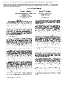
SPLD has a natural relationship to component software principles. Commonalities discovered in SPLD can be applied to the development of components. In our work, component-based development processes require the combination of top-down principles in addition to bottom-up, iterative techniques. More specifically, a successful component must support the system features specified when analyzing a specific domain in addition to having the modularity and flexibility to support the utilization or composition during implementation. In this paper, there is a combination of a well-known evolutionary development process, RUP, and the principles of SPLD. The Engineering Software Architectures, Processes and Platforms for System-Families (ESAPS) reference process [10] is a SPLD process where the domain analysis and development is executed in parallel to the application-level development, though there are several integrated sections. This approach is just one representative SPLD technique, and the authors recognize that there are many other frameworks [12][15]. However, the ESAPS reference process provides the best foundation for our approach, since there is a strong focus toward component development. The work presented in this paper extends the ESAPS approach by focusing on its relation to an evolutionary development process (i.e. the Rational Unified Process (RUP)). In our work, we combine the domain engineering process and the application engineering process defined in ESAPS into a customized RUP. The requirements/analysis, design, and implementation/coding phases of the ESAPS dual processes are in the same sequence as the sub-process phases of RUP. This relation is illustrated in Figure 1. RUP supports a use case-driven approach. Since use cases can define the business-level and system-level requirements of the system, they can be applied throughout the software development lifecycle for analysis, design, development, and testing. Though RUP is consistent with both the domain engineering and application engineering processes in ESAPS, it does not specifically support an integrated approach (in its current form). A major innovation of this work is to extend RUP with processes to support integrative domain analysis and application analysis using use case-driven approaches. This approach is discussed in detail in the following section.
Domain Analysis
Domain Design *
Domain Engineering
* Domain-Specific
Domain Implementation *
Reference * Architecture
Reusable Components * *
Requirements
Architecture
Application Requirements
Application Design
Components
Application Engineering
2. USE CASE-DRIVEN PRODUCT LINE ANALYSIS The idea of product lines is not new in the manufacturing domain. Particularly in the automotive industry, product lines have been used to reduce cost by exploiting the commonalities of products. SPLD can be used similarly to promote cross-application reuse. The major concept of this approach is to use the knowledge of domain experts to help understand the commonalities of a class of applications. Once these commonalities are determined, a software framework can be developed to support a common baseline for relevant applications or products [12].
Feedback/ Adapatation / Reverse Architecting
New Requirements
Business Requirements Modeling
Analysis and Design
Application Coding
Implementation
Test
Use-Case Driven Rational Unified Process
Figure 1. Aligning RUP with the ESAPS Reference Model.
3. COMPONENT-BASED PRODUCT LINE ANALYSIS AND DESIGN In this paper, a new development process is created based on a customization of RUP. The major difference is that this process jointly supports domain engineering and application engineering within one analysis, design and development process. This new approach is called Component-Based Product Line Analysis and Design (C-PLAD). C-PLAD is divided into six high-level phases. These phases are Specification, Requirements, High-Level Use Cases, Component-Level Use Cases, Software Design and Development, and Testing. The software design and development phase and the testing phase are iterative phases. The C-PLAD process is illustrated in Figure 2. Each of the phases can be defined in more detailed as follows. •
Specification. The C-PLAD approach takes a similar approach to system conceptualization as the Object Modeling Technique (OMT) [14]. The initial system description is written in the form of a problem statement. This problem statement is written jointly by the domain expert and the software engineers. The problem statement represents the initial high-level understanding of the problem domain or class of applications.
•
Requirements. In the requirements phase, software engineers again consult with the domain experts to draft a set of written requirements which scopes the project. The focus of the software engineers should be to separate system features from software requirements. In context of a class of applications, this represents the separation of functional concerns from nonfunctional concerns.
•
High-Level Use Cases. The first two phases are similar to both the RUP and OMT development phases. Though the high-level use case phase is also related, it is in this phase that specific C-PLAD use case templates are employed to characterize the specific product. Based on the initial problem statement and requirements, software engineers draft an initial set of use cases in this phase. These high-
level use cases characterize the sample applications in this particular product line in addition to the separation of functional and nonfunctional use cases. •
•
Component-Level Use Cases. This component-level use case phase represents an innovation in the C-PLAD approach. This phase consists of a step-wise iterative process for extracting component-level use cases from the high-level use cases in the previous phase. Component-level use cases are specified where actors typically are other components. In addition to developing the C-PLAD-specific use case templates, software engineers must collaborate with domain experts to assure accuracy. Software Design and Development. Using standard RUP techniques, the component-based use cases are used to continue the design and implementation process. In this phase, structural and dynamic models (class and sequence diagrams, respectively) are created to represent each component. In this phase, software engineers focus on designing clean interfaces to the component to support composition.
S p e c ific a tio n R e q u ire m e n ts
H ig h -L e v e l U se C ases
•
Testing. The testing phase is an iterative phase with the software design and development phase. In this phase, components are composed and tested for the set of sample applications as modeled in the high-level and componentlevel use cases. Problems discovered in the testing phase are used to adapt the component-based design. To support traceability, use case component-level models are updated based on changes in this phase. Similar to RUP, C-PLAD relies heavily on analysis based on use case-driven techniques. A major innovation in this approach is a specific step-wise process for creating use cases that support both application-level and domain-level analysis. This approach introduces new specific use case templates to assist this step-wise process. This step-wise process ultimately results in component-based use cases. The component-based use cases can then follow the original RUP techniques for implementation. The following section describes this step-wise process and the C-PLAD use case templates supporting the approach.
C o m p o n e n tLevel U se C ases
A p p lic a tio n Level
A p p lic a tio n S p e c ific a ito n
T e s tin g
Ite ra tiv e D e s ig n , D e v e lo p m e n t, a n d T e s tin g
S y s te m F e a tu re s Com ponent 1 ..n
S o ftw a re R e q u ire m e n ts
S o ftw a re D e s ig n a n d D e v e lo p m e n t
C la s s D ia g ra m s a n d S e q u e n c e D ia g ra m s
Test S c rip ts
F u n c tio n a l In fra s tru c tu re
A p p lic a tio n -L e v e l D o c u m e n ta tio n : S p e c ific a tio n , R e q u ire m e n ts a n d S y s te m -L e v e l U s e C a s e s
Com ponent 1 ..n
C o m p o n e n t D o c u m e n ta tio n : U s e C a s e s , C la s s D ia g ra m s , S e q u e n c e D ia g ra m s , a n d S o ftw a re A P Is fo r e a c h c o m p o n e n t
Figure 2. C-PLAD Approach.
4. SYSTEMATIC USE CASE-DRIVEN SPECIFICATION PROCESS The major innovation of the C-PLAD approach is the development of the component-based use cases using a step-wise approach. This step-wise approach encompasses both high-level use case and component-level use case phases. In this section, there is a discussion of the creation of the high-level use cases and their artifacts. The subsequent section contains details on how the component-level use cases are formed.
4.1 C-PLAD High-Level Template The C-PLAD step-wise approach is highly dependent on the initial phases of specification and requirements. The problem statement, system features, and software requirements represent the necessary artifacts for constructing the initial high-level use case diagram. The C-PLAD approach introduces a specific template for the high-level use case model. This template and its relation to other diagrams are shown in Figure 3. As a written document, the problem statement typically describes both the domain of the system to be designed in addition to an initial explanation of its features. An experienced software engineer can craft this document based on collaboration with a domain expert.
Subsequently, a requirements document can be created to clarify the system features and software requirements. In the C-PLAD approach, the high-level template is a one-page view of the system. As shown in Figure 3, the application layer in the upper portion of the high-level template contains a list of domain-related applications (SpecificApplication1..n) which are derived into a class of applications or a product line (Application Domain/Product Line Applications). Though the use of the hollow-tip arrow is a generalization relationship, the authors
acknowledge that the application domain is more accurately the intersection of all the specific applications. The lower portion of the template contains a grouping of functional capabilities and nonfunctional capabilities. These capabilities can be derived from the features and software requirements of the written requirements. This is accurately shown with the hollow-tip arrow. It is these capabilities that will be further grouped into components.
C - P L A D H ig h -L e v e l T e m p la te
P r o b le m S ta te m e n t Specific Application_2
W r itte n Text
Specific Applications_1
Specific Application_n
D e riv e d C la s s o f A p p lic a to n s Application D omain/Product Application Layer Line A pplications --------------------------------------------------------------------------------------------------------------------------------------------------------------------------
Component General Functional ity
C omponent Framework
W r itte n R e q u ir e m e n ts Functional Capabilities
F e a tu re s
Nonfunctional C apabilties
D e riv e d F u n c tio n a l R e q u ire m e n ts General Capability_1
S o ftw a r e
General Capability_n
C ommon Service_n C ommon Services_1
General Capability_2
D e riv e d N o n fu n c tio n a l R e q u ire m e n ts
Figure 3. C-PLAD High Level Template. As an example of this approach, consider a class of applications that require software that controls an audio tape recorder. At the application layer, the product line is the class of tape recorder control software. This software may be specialized to applications such as a personal radio, telephone answering machine, and personal dictation recorder. A software engineer could collaborate with a domain expert to determine that a feasible initial set of general component functions may be record, play, and insert cassette, while nonfunctional capabilities might include error-handling and speed control as shown in Figure 4.
Personal Radio (Walkman)
Personal Dictation Recorder
Tape Recorder Application Layer Control -----------------------------------------------------------------------------------------------------------------------... Component General Functionality
Component Framework
Functional Capabilities
4.2 Iterative Analysis Process The C-PLAD high-level template serves both as the high-level view and as the roadmap to an iterative analysis process. Once the initial high-level template is created, a reasonable assumption may be that the general capabilities (GeneralCapability1..n) represent potential components.
Telephone Answering Machine
Record
Nonfunctional Capabilties
Cassette Insertion Play
Speed Control Error-Handling
Figure 4. High-Level Template for a Class of Applications Containing Tape Recorders.
However, in our work in the medical domain of image-guided surgery, it was discovered that a mixture of the underlying functions represent a more logical component when abstracting functions for a class of applications. As such, an iterative process was created to help discover the most efficient grouping of functions for creating software components. The process consists of four steps as illustrated in Figure 5. In the first step, the software engineer begins to further describe each of the General Capabilities, one at a time. As in step 2, each time the software engineer moves to a new capability, new joint capabilities may be discovered. In addition, new common services may be discovered. Once all capabilities have been detailed with help from the domain experts, in step 3, the software engineer should create application-level use case diagrams using the General Capabilities use cases as building blocks. Revisit earlier use cases
1. Specialize Each General Capability, one at a time
Record Speaker
4. Use all applicationlevel use cases to discover common functionality
In addition, in step 3, software engineers may discover functionality to add to the General Capability and the underlying lower-level functions. An example, based on the earlier highlevel template, is shown in Figure 6. A software engineer may propose initial general component functionality of Record and Play for the tape recorder product line. As in the first step shown in Figure 5, the Record use case may be further defined with user cases such as Translate Sound to Tape Format and Write to Tape. A similar approach is used to specialize the play use case. During this process of further detailing the general use cases, several discovered use cases may be common to both record and play. The authors acknowledge that this is an intuitive example, however additional examples will be shown in the following sections. «uses» Record
Play
«uses» «uses»
«uses»
«uses»Check Tape Inserted Write to Tape
Record Phone Caller Message
«uses» «uses»
«uses» Listen for Record Event
«uses» «uses»
«uses» Write to Tape
Phone Ringing Listener
Figure 5. Iterative Use Case Creation Process
Translate Sound to Tape Format
«uses»
Access External Microphone
3. Use lowlevel use cases to compose each application, one at a time
Add new low-level use cases discovered
2. As you move to each General Capability, look for situations where one General Capability uses another and, also be aware of the need for new Common Services
«uses»
component use cases to develop components that are relevant across a family of applications. Likewise, component functionality specific to a particular application are discovered. Figure 7 demonstrates this approach. Similar to the approach in step 2 of Figure 5, iterative creation of application-level use cases also helps to determine functional intersections. In Figure 7, Write to Tape is an intersection of the Dictation Machine and Answering Machine functionality.
Translate Tape «uses» Format to Sound
Assure Tape Not Ended
New Common Services
Figure 6. Common Use Cases among General Functionality. Finally, in step 4, common component use cases and specialized component use cases are extracted from the application-level use cases. This extraction is performed via an inspection of the resulting use case diagrams. Software designers use the common
Access Phone Receiver
Dynamic Sound-Level Adjust
Specialized Component
Common Component
Specialized Component
Figure 7. Deciphering Common and Specialized Component Functional Use Cases.
5. IMAGE-GUIDED SURGERY: A C-PLAD EXPERIENCE REPORT The Imaging Science and Information Systems (ISIS) group is a multi-disciplinary research group in the Department of Radiology within Georgetown University’s Medical Center. One of the research group’s major concentrations is the development of prototype systems in the image-guided surgery domain. The CPLAD approach was used to develop a component framework to support rapid application development of these prototype systems [5][6]. Image-guided surgery is a rapidly developing field, since these procedures mean substantially less trauma for the patient. Image guidance was originally developed for neurosurgical applications since navigation in the brain requires great precision. This technology allows the physician to use pre-operative computed tomography (CT) or magnetic resonance imaging (MRI) scans to guide minimally invasive procedures. The domain of image-guided surgery systems incorporating an electromagnetic tracking device is illustrated in Figure 8. This diagram is based on a subset of the C-PLAD high-level template of this domain mapped to several exemplar requirements. In the scope of this paper, it is not possible to describe the entire domain of image-guided surgery using C-PLAD. However, the functionality required for registration demonstrates the richness of the use case models that have been created using the C-PLAD approach. In image-guided surgery, registration is the process of mapping the pre-operative imaging data set (typically computed tomography (CT) or magnetic resonance imaging (MRI)) with an intraoperative tracking device. The final use case showing the registration component is illustrated in Figure 9. The stereotypes , , and , show how common functionality is discovered using the C-PLAD approach.
IGBiopsy
Guidewire Tracking
Bone Screw Placement
Radio Frequency Ablation
Clinician/Doc IGSTK Application tor Application Layer
--------------------------------------------------------------------------------------------------------------------------------------------------------------------------
General Functionality
Component Framework Medical App Developer
Common Interfaces Functional Capabilities
Non-Functional Capabilities
Common Services
Magnetic Tracking Interface
Registration
Segmentation Visualization
Image Reader Interface
Standardized Visualization
Figure 8. System Features and C-PLAD High-Level Use Case Model.
Copied and further defined from Main Use Case Diagram
Manage Current Manage Final Transform Transform
Touch Fiducials
Managing Interface to Registration Managing User Actions StandardVisualization from GUI
Translate Fiducials to Mag Space
Managing Connection to Managing Image Reader Common Services Connection
Touch Fiducials in CT Space
Capture User Input
Start Optimization
Configure Moving Image Configure Fixed Image Manage Optimizer Parameters Process Actions
Define Stopping Criteria Place Fiducials Place Catheter
Figure 9. Final Registration Use Case Diagram.
6. EVALUATION To evaluate the effectiveness of the C-PLAD approach, metrics were recorded for each iterative phase where a new application was composed of low-level use cases. The ISIS team initially identified four applications for the image-guided surgery components. These applications are shown in Application Layer of Figure 8. It is not in the scope of this paper to describe each application in detail. However, it is important to understand that all applications fit within the image-guided surgery product line. The ISIS team agreed that the registration component represented the component that was most understood by the software engineers and the domain experts. In addition, this component also represented the best candidate for development into a component in the opinion of the team based on its perceived use in multiple applications. The number of use cases representing the registration component, the total number of components, and the number of components removed/added at a particular iteration were recorded. At the time of this paper, C-PLAD was only evaluated using the first two applications. The recorded metrics are listed in Table 1. It was anticipated that the number of use cases for the registration component would decrease as the additional applications were included. Also, a decrease in the total number of components would occur as functionality was grouped into components. Table 1. Metrics using C-PLAD for Image-Guided Surgery. Design Iteration Problem Statement and Requirements Liver Biopsy Guidewire Placement
Number of Use Cases for Registration
Number of Components All Removed Added
6
20
Initial
Initial
12
14
8
2
7
18
1
5
In evaluating the C-PLAD approach, there were several significant observations. The first observation was the variation in the number of use cases (registration component) for each of the C-PLAD iterations. The research team anticipated a decrease in the number of use cases for the registration component during the first iteration. The team predicted that the number of use cases would increase as only the most common use cases would remain. However, after incorporating the first application (i.e. Liver Biopsy), the number of use cases increased from 6 to 12. The increase in use cases was based on additional unanticipated functionality that became obvious in the second step of the CPLAD approach where use cases for one component are used to complete other components. This increase in use cases is a logical result that shows the ability of the C-PLAD approach to help identify unsuspected requirements. Furthermore, after incorporating the second application (i.e. Guidewire Placement), five use cases were determined to be too specific and removed from the components functionality. In this case, the C-PLAD approach assisted in maintaining the robustness of the registration component. A second observation was made based on the change in the number of components during C-PLAD iterations. Through the collaboration of the domain specialists and software engineers,
there were 20 components considered initially. After incorporating the first application, the total number of components decreased to 14. Eight components were removed, and two components were added. This result was as anticipated since it was the expectation that only common components would remain. However, there was an increase of 4 components when incorporating the second application. This increase consisted mostly of the addition of common cross-cutting components. Also, other components were decomposed into multiple components.
7.
DISCUSSION
C-PLAD addresses a gap in the RUP Core Workflows [15]. RUP advocates use-case driven requirements analysis, producing an analysis model that is used as input to the architecture description definition process. The use case model is inherently vertical; it drills down through vertical slices of functionality supported by the system as a whole. It is then the architect’s job to take this model, identify commonalities, and begin sketching core objects and components of the system using tools such as analysis classes and component diagrams. In other words, the architect is solely responsible for translation of a vertical model (the use case model) to a potentially horizontal one (the architecture description). This is natural given the evolution of RUP, combining a use-case driven process with architecture-centric notations. This problem is exacerbated in component-based product line development. The need to identify components early, produce them at an appropriate level of generality, and leverage existing components in the product line impose constraints that could be addressed if component interactions and dependencies were better understood earlier in the development process. RUP suggests that component diagrams should begin as part of the deployment core workflow by this time, but these diagrams are better suited for deployment as they identify packaging and location constraints between components. RUP also includes the nebulous notion of a “service package”, naming a collection of service-oriented features so dependencies may be created to these services in analysis packages. However, little guidance is given as to how one arrives at a service package. UML 2.0 introduces notation for reusing sequence diagrams called “Interaction Occurrences”. This new element allows a modeler to model primitive message interactions for reuse by higher-order, complex interactions. In other words, sequence diagrams now have modular reuse. The CPLAD approach pushes the modularity upstream into the use cases itself, so explicit requirements exist for the modular components. C-PLAD offers an alternative. C-PLAD suggests extending use cases to capture component interactions and dependencies as part of the analysis model by having components serve as first-class objects in the use case model. The step-wise iterative process allows C-PLAD to be used as a tool in the gap area between requirements analysis and architecture, while the High Level Template (see Figure 3) supports traceability between high-level domain concepts and application engineering concepts that leverage components. C-PLAD has the additional benefit that such models may be discussed with customers as they are represented in a familiar notation (use cases). Finally, the CPLAD step can be inserted into the RUP Core Workflows seamlessly; for example, the development of detailed component
diagrams downstream should reconcile with the component-level use cases identified during step-wise refinement. Another major benefit of the C-PLAD approach is the processbased approach to discovering the most robust components for development while identifying common components. Most of the components added in incorporating both applications were common nonfunctional components and through the decomposition of components. In initial cases, it is common for the software engineers to focus on the functional aspects of the components, while the tendency is to neglect the crosscutting aspects, such as logging, data management, exception-handling, and user communication. The C-PLAD approach was effective for discovering common components for such nonfunctional concerns. The C-PLAD approach also assisted in determining components that encapsulated too much functionality. The CPLAD approach results in detailed use case diagrams. Use cases at the bottom-level of such diagrams can be effectively translated into system functions as in related work [4] and into sequence diagrams as in UML 2.0. In this paper, the main focus is on conceiving the use cases, but, in future work, we plan to describe the translation of the use cases into concrete representations. The C-PLAD approach has a different perspective than current approaches to refactoring. Using the C-PLAD approach, reuse is built into components while refactoring promotes the change of software designs with evolving requirements. The C-PLAD approach is most effective for projects that are aware of at least a subset of target applications. In future work, we plan to extend CPLAD to allow for the necessary refactoring with the introduction of new unanticipated applications.
8. CONCLUSIONS
Government. We also acknowledge the fruitful conversations with Will Schroeder of Kitware Incorporated.
10. REFERENCES [1] Batory, D., Johnson, C., MacDonald, B. and von Heeder, D. "Achieving Extensibility Through Product-Lines and Domain-Specific Languages: A Case Study", ACM Transactions on Software Engineering and Methodology, April 2002 [2] Beck, K. “Extreme Programming Explained, Embrace Change”, Addison-Wesley Professional, Boston, Ma, 2000 [3] Booch, G. Rumbaugh, J, and Jacobson, I. “The Unified Modeling Language User Guide”, Addison Wesley, Reading, MA 1999 [4] Bruegge, B. and Dutoit, A.H. Object-Oriented Software Engineering Using UML, Patterns, and Java. 2nd Edition Prentice Hall, Englewood Cliffs, NJ 2003 [5] Cleary, K., Clifford, M., Stoianovici, D., Freedman, M.T., Mun, S.K., Watson, V. “Technology improvements for image-guided and minimally invasive spine procedures” IEEE Transactions on Information Technology in Biomedicine Vol. 6, No. 4, pp 249-261, 2002 [6] Cleary, K., Ibanez, L., Ranjan, S.R., and Blake, M.B. “IGSTK: A Software Toolkit for Image-Guided Surgery Applications”, Proceedings of the 18th International Conference on Computer-Assisted Radiology (CARS2004), Chicago, IL, June 2004, Elsevier, 473-479. [7] Cockburn, A. Agile Software Development. Addison-Wesley 2002
In this paper, a new software engineering process is introduced to support component-based software engineering for a specific class of applications. Using a use case-driven approach, a major innovation in this work is a principled approach to identifying requirements to support the development of general components for a specific product line. The C-PLAD approach varies from standard product line analysis because it addresses projects that are aware of a significant subset of target applications. In these cases, it is valuable if reuse can be incorporated in the design to help prevent the need for large-scale refactoring later. Although this work has been useful in the development of a componentbased framework for image-guided surgery, there is one major area of future work. In the scope of the initial studies, only a few components were developed and a subset of the identified applications. In the future, the C-PLAD analysis needs to incorporate other applications within the image-guided surgery product line. In addition, we plan to build new applications consisting mainly of the components designed using the C-PLAD approach. The ability of the C-PLAD-generated components to fulfill new applications will help evaluate the accuracy of the approach while identifying areas for improvement.
[8] Heineman, G.T. and Councill, W.T. Editors, ComponentBased Software Engineering: Putting the Pieces Together, Addison-Wesley, Boston, MA June 2001
9. ACKNOWLEDGMENTS
[14] Rumbaugh, J., Blaha, M., Premerlani, W., Eddy, F. ,and Lorensen, W. Object-Oriented Modeling and Design. Prentice Hall 1991
This research is supported by the National Institute of Biomedical Imaging and Bioengineering (NIBIB) at the National Institute of Health (NIH) under grant R41 EB000374-01A1 and by U.S. Army grant DAMD17-99-1-9022. The content of this manuscript does not necessarily reflect the position or policy of the U.S.
[9] Kruchten, P. (2000). The Rational Unified Process—An Introduction, Second Edition, Addison-Wesley [10] Lerchundi, R. (Ed.) (2003-05-18). System Family Process Frameworks,http://www.esi.es/en/Projects/esaps/publicpdf/CWD212-21-02-01.pdf SEI CMM (2003-04-25). Capability Maturity Model for Software, http://www.sei.cmu.edu/cmm/ [11] Li, H., Krishnamurthi,, S., and Fisler, K. ”Verifying CrossCutting Features as Open Systems”, Proceedings of the International Conference on Foundations of Software Engineering, Charleston, S.C. 2002 [12] M. Eriksson (2003): An Introduction to Software Product Line Development, Proceedings of Umeå's Seventh Student Conference in Computing Science, UMINF 03.05, ISSN0348-0542, pp. 26-37. [13] Rosenberg, D. (2001) Use Case Driven Modeling with UML: A Practical Approach, Addison-Wesley
[15] SEI PLP (2003). Framework for Product Line Practice, http://www.sei.cmu.edu/plp/