Aug 20, 1993 - Electrical Engineering, The Pennsylvania State University. 5 Longtin, D.R., DePiero, ..... in a SENTRAN7 sensitivity study ii a two-step process. Users must first define ...... 1z3z 33a 1r0 ZUPV DX= I. n3]. AND r'MAB7 W0WZLIZ ...
AD-A278 562.
7
PL-TR-93-2197ADA
56
Users Guide For SENTRAN7, Version 2.0
David R. Longtin John R. Humnml
SPARTA, Inc. 24 Harteli Avenue Lexington, MA 02173
x
C'i~ 9 4 -08.6
20 A ugust 1993
94-08765 U
Scientific Report No.66,
I Approved for public release; distribution unlimited
PHILLIPS LABORATORY tDirectorate of Geophysics AIR FORCE MATERIEL COMMAND HANSCOM AIR FORCE BASE, MA 01731-3010 .
0..
"This technical report has been reviewed and is approved for publication."
(Signature) (Signatture)
(Sgntue
CAPT MARK A. CLOUTIER Contract Manager
DONALD E. 0O Chief Measurements Branch
(Signature) ROGER A. VAN TASSEL Director Optical Environment Division
This report has been reviewed by the ESC Public Affairs Office (PA) and is releasable to the National Technical Information Service (NTIS).
Qualified requestors may obtain additional copies from the Defense Technical Information Center. All others should apply to the National Technical Information Service.
If your address has changed, or if you wish to be removed from the mailing list, or if the addressee is no longer employed by your organization, please notify PL/TSI, 29 Randolph Rd. Hanscom AFB, MA 01731-3010. This will assist us in maintaining a current mailing list. Do not return copies of this report unless contractual obligations or notices on a specific document requires that it be returned.
REPORT DOCUMENTATION PAGE
Form Aoppved OMB No. 0704-0188
I
.. . seec "**v d" eti u is sonused to werae I how pet re•nni otk oldan dW hburdn for PuMc usp•Htig neead aind m-VII atd roIeIkg ft omWlb cI f•,ommb Send corelunt regardirV tis bude edtinue or wmyWier aped of fth Wa6di td, e gletd Rot. 1216 .erarson aohlecout ihfmuian. I dAdI suggestons for redurfg tis burden. la Wahbtoon HeadquanWs Servisee Directoate for lidamfta Operadons endPA end Sudge Pq-ewo Reduclon Project (070W48, Wsship. . DC 2060 0-16 WHON" SUN1204. Mngt^ VA 2202-4=0. and l the Ofice d Manogentm *M &.REPORT TYPE AND DATES COVERED 2. REPORT DATE 1. AGENCY USE ONLY (Leave blmW
20 AUG 1993
Scientific Report, No. 6 5. FUNDING NUMBERS
4. TITLE AND SUBTITLE
Users Guide for SENTRAN7, Version 2.0 PE 35160 F PR 7670 TA 15 WUBB
K rroR(s)
F19628-91-C-0093
David R. Longtin and John R. Hummel
8. PERFORMING ORGANIZATION
7. P•RF-OnmNG ORGANIZATION NAME(S) AND AODRESS(Es)
REPORT NUMBER
SPARTA, Inc. 24 Hartwell Avenue Lexington, MA 02173
LTR93-013
L SPONSORING I MONITORING AGENCY NAME(S) AND ADDRESS(ES)
10. SPONSORING / MONITORING AGENCY REPORT NUMBER
Phillips Laboratory 29 Randolph Road Hanscom AFB, MA 01731-3010 Contract Manager: Capt. Mark Cloutier/GPOA
PL-TR-93-2197
11. SUPPLEMENTARY NOTES
12a. DISTRIBUTION / AVAILABILITY STATEMENT
1 2b.
DISTRIBUTION CODE
Approved for Public Release; Distribution Unlimited I.
ABSTRACT (MHxiuum 200 words)
SENTRAN7 is a user friendly interface system to LOWTRAN7 and MODTRAN. The code permits users to rapidly evaluate atmospheric conditions and path geometries. The main features of SENTRAN7 include: (1) interactive entry of LOWTRAN7/MODTRAN input parameters and directives for their perturbation, (2) intelligent generation of LOWTRAN7/MODTRAN input deck images, (3) autonomous post-processing of LOWTRAN7/MODTRAN outputs for data extraction, analysis and 3D graphical display, and (4) a help utility. The thrust of the current effort is to incorporate new features and enhancements into SENTRAN7. The new code is called SENTRAN7, Version 2.0. The new features include: (1) the capability to impose random and percent perturbations by layer on user-defined profiles of atmospheric constituents, (2) a comprehensive error checking package that checks user-defined profiles of atmospheric constituents, (3) an option to save LOWTRAN/MODTRAN output as customized file names, and (4) a general purpose module that permits users to view the contents of files of their choosing. '14. SUBJECT TERMS
15. NUMBER OF PAGES
SENTRAN7, MODTRAN, LOWTRAN7, Sensitivity Studies, Random Perturbations, User Interface, Users Guide
16. PRICE CODE
17. SECURITY CLASSIFICATION
20. UMITATION OF ABSTRACT
OF REPORT
Unclassified NSN 7540-01-280-5500
18. SECURITY CLASSIFICATION
OF THIS PAGE
Unclassified
19. SECURITY CLASSIFICATION
148
OF ABSTRACT
Unclassified
SAR Standard Form 298 (Rev. 2-89) Prescrbed by ANSI SWd.Z39.1S 2M-102
Aooession
For
NTIS GRA&I DTIC TAB Unaurounced or
[
DIItributlQn/ Avallability 4oden Digit
J~ftl arudor Sptecia1
Table of Contents 1 INTRODUCTION 1.1 Background and Purpose of Study 1.2 Organization of the Report 2 WORK PERFORMED ON SENTRAN7
1 1 2 3
2.1
Notations Used in This Report
3
2.2 2.3
Brief Overview of SENTRAN7 Default to MODTRAN
4 4
2.4
Default to "LOG ON"
4
2.5
Error Checking on User-Defined Atmospheric Profiles 2.5.1 Types of Errors To Be Identified 2.5.2 Major Errors 2.5.2.1 Error Checking on Altitude Profiles 2.5.2.2 Error Checking on Pressure Profiles 2.5.2.3 Error Checking on Temperature Profiles 2.5.2.4 Error Checking on Water Vapor Profiles 2.5.2.5 Error Checking on Other Gas Constituent Profiles 2.5.2.6 Error Checking on Aerosol Profiles 2.5.2.7 Error Checking on Aerosol Wavelength Scaling Factors 2.5.3 Warning Messages 2.5.3.1 Overview 2.5.3.2 Atmospheric Variables Checked for Reasonability 2.5.3.3 Atmospheric Variables Not Checked for Reasonability 2.6 Improved Perurnation Schemes for User-Defined Atmospheres 2.6.1 Deterministic Perturbations 2.6.2 Correlated and Uncorrelated Random Perturbations 2.6.3 Pertrbable Atmospheric Variables 2.7 View File Module
5 5 6 6 6 8 8 8 9 9 10 10 10 11 11 12 12 13 14
2.8
15
Renaming of Output Files from LOWTRAN7 and MODTRAN
Hi
2.9 Optional Display of Absorbing Species 2.10 Improved Method of Perturbation for Card 2C3 Parameters 3 INSTALLJNG AND RUNNING SENTRAN7 3.1 Overview of Software 3.2 Installing the Program 3.3 LOWTRAN7 and MODTRAN Requirements 3.4 Using the DIRECT.ORY File 4 USERS GUIDE FOR SENTRAN7 4.1 Overview of SENTRAN7 4.1.1 Code Philosophy 4.1.2 Design Criteria 4.2 Program Structure 4.2.1 Help Module 4.2.2 Load/Save Module 4.2.3 Define Perturbations Module 4.2.3.1 Overview 4.2.3.2 Define Deterministic Perturbations Option 4.2.3.3 Define Random Perturbations Option 4.2.3.4 Select a Random Number Generator for Random Perturbations 4.2.3.5 Invoke Deterministic and Random Perturbations 4.2.3.6 Files With Deterministic and Random Perturbation Profiles 4.2.3.7 Restrictions in the YRO File 4.2.3.8 Limited Consistency Checks 4.2.4 Edit Module 4.2.4.1 General Information 4.2.4.2 Movement in the Edit Menus 4.2.4.3 Data Entry 4.2.4.4 Perturbing Data 4.2.4.5 Entry of Perturbations for Card 2C3 Parameters 4.2.4.6 On-line Help Utility 4.2.4.7 Additional Notes 4.2.5 Compile Module 4.2.5.1 Invoking the Compile Module 4.2.5.2 MESH and NOMESH Compiler Options 4.2.5.3 Error File Option 4.2.6 Select Module 4.2.7 Run Module 4.2.7.1 Invoking the Run Module 4.2.7.2 Save Output Files Option 4.2.8 Graph and Analyze Module 4.2.8.1 Types of Plots Available 4.2.8.2 Invoking the Graph and Analyze Module 4.2.8.3 Specifying the Plotting Parameters 4.2.8.4 Restrictions Imposed by the Graph and Analyze Module 4.2.8.5 Commands Available With the Graph and Analyze Module
iv
15 15 16 16 16 18 18 19 19 19 20 21 21 21 24 24 25 27 27 31 33 34 34 37 37 37 39 40 43 44 44 45 46 47 48 48 49 50 50 52 52 54 54 55 55
4.2.8.6 Viewing SENTRAN7 Plots on a SUN"' Computer 4.2.9 Plotting Trace Gas Input Profiles 4.2.10 View File Module 4.2.11 Miscellaneous 4.2.11.1 LOG Command 4.2.11.2 ABS Command 4.2.11.3 NOPROMPT Command 4.2.11.4 ZAP Command 4.3 Error Checking Package 4.3.1 Implementation 4.3.2 First Example of the Error Checking Package 4.3.3 Second Example of the Error Checking Package 5 SENTRAN7 TUTORIALS 5.1 Basic Concepts of the User Interface 5.2 Conventions Used in the Tutorials 5.3 SENTRAN7 Tutorial #1 5.3.1 Getting Started 5.3.2 Using the Load and Save Module 5.3.3 Using the Edit Module 5.3.4 Using the Run Module 5.3.5 Using the Graph and Analyze Module For Tutorial #1 5.4 SENTRAN7 Tutorial #2 5.4.1 Using the Edit Module 5.4.2 Using the Compile and Run Modules 5.4.3 Using the Graph and Analyze Module for Tutorial #2 6 SUMMARY AND RECOMMENDATIONS FOR FUTURE STUDIES 6.1 Summary 6.2 Recommendations for Future Studies 6.2.1 Incorporation of Aerosol and Other Climatologies 6.2.2 Windows-Based Menu System 6.2.3 Sensitivity Studies With a "Build Your Own" Aerosol Layer 6.2.4 Other PL Codes References APPENDIX A FILE STRUCTURE A. 1 Methodology File A.2 LOWTRAN and MODTRAN Input File A.3 Model Atmosphere Data File A.4 Aerosol Extinction Coefficients Data File A.5 Aerosol Phase Functions Data File A.6 Random Perturbations Data File A.7 LOWTRAN7 and MODTRAN Output Files A.8 Customized Output Files A.9 3D Files A.10 Graphics File A.11 Cosmetic File
60 60 65 68 68 69 70 70 71 71 71 73 75 75 75 76 76 76 79 88 89 101 101 103 103 107 107 107 107 118 109 110 112 114 115 115 115 116 116 117 117 118 119 119 119
A.12 SEN.ERR File A.13 SENW.WG File A.14 RANDOM).DATFile A.15 RANDOM2.DAT File A.16 Help File APPENDIX B CODE CHANGES TO LOWTRAN7 AND MODTRAN APPENDIX C QUICK REFERENCE GUIDE FOR SENTRAN7 APPENDIX D GRAPH AND ANALYZE MODULE FLOW CHART
120 120 120 121 121 122 126 134
List of Figures 1.
Example of a File Listing With SENTRAN7's View File Module
14
2.
Display of the SENTRAN7 Version 2.0 Main Menu
22
3.
The Introductory Help Screen in the Help Module
23
4.
Display of the Define Perturbations Submenu
25
5.
Example of the Command Used to Define Deterministic Perturbations
26
6.
Menu to Define the First Set of Deterministic Perturbations
26
7.
Example of the Final Screen Displayed After Defining the First Set of Deterministic Perturbations
28
8.
Example of the Command Used to Define Random Perturbations
28
9.
Menu Displayed to Define Correlated and Uncorrelated Random Perturbations
39
10.
Example of the Final Screen Displayed After Defining Random Perturbations
30
11.
Menu Used to Select the Random Number Sequence To Be Used When Generating Correlated and Uncorrelated Random Perturbation Profiles
31
vi
12. 13. 14. 15. 16. 17. 18. 19. 20. 21. 22.
Menu Showing the Command Used To Invoke Deterministic Perturbations on the Edit Card 2C Menu Menu Showing the Command Used To Invoke Random Perturbations Example of the RANDOMI DAT File Which Contains Tabulated Values of Randomly Perturbed Profiles Example of the RANDOM2.DAT File Which Contains a Statistical Analysis of Randomly Perturbed Profiles Example of a SENTRAN7 Editing Screen for MODTRAN Card 1
32 32 35 36 38
Prompt Message Used to Check the Variables on a Given MODTRAN Input 40 Card Example of the Edit Card 2C Menu After the User Has Specified 44 Perturbations for the IHAI Parameter Example of an On-line Help Screen That Can Be Called Within Editing Module of SENTRAN7 SENTRAN7 Screen Displaying Which Model Program to Execute An Example Showing How to Use the Save Output File Option in the Run Module Example of SENTRAN7 Informing Users That Customized File Names Are Being Used to Store Program Output
45 49 51 51 54
25.
Example of an Initial Screen in the Graph and Analyze Module An Example of a Submenu in the SENTRAN7 Graph and Analyze Module Used to Define the Parameters To Be Plotted An Example of a Graph from the SENTRAN7 Graph and Analyze Module
26. 27.
61 On-Line Help Screen Within Graph and Analyze Module of SENTRAN7 Example of the Command to Perturb theO 3 Input Profile in Card 2C by 20 % 63
28.
Example of the Command to Move the Cursor Up One Line to the 03 Parameter on Card 2C Example of the Command to Write the O3 Input Profile in Card 2C to a Data File Example of the Screen Displayed After the 03 Input Profile Has Been Written to a File Sample Trace Gas Input Profile Data File 033D
23. 24.
29. 30. 31. 32. 33. 34.
Example of a 2D Plot of 03 Input Profile with 20 % Perturbations Prompt Displayed in the View File Module to Enter the File Name To Be Viewed Example of a File Listing in the View File Module viH
56 56
63 64 64 65 66 67 67
35.
Directory Listing in the View File Module After Users Try to View a File That Does Not Exist
68
36.
Example of the Main Menu Display When the Log File Is Active
69
37.
Example of the Main Menu Display After the Listing of the Activate Molecular Absorbers Has Been Turned Off 70
38.
Example of a Message Displayed in the Edit Module To Inform the User That Major Errors Were Detected 72
39.
Example of a Message Given in the Edit Module To Inform the User That Warning Conditions Were Detected
72
40.
Example of the Information Sent to the SENLOG File from the SENTRAN7 Error Checking Package After Accessing An Atmospheric Profile File That Contained Errors in the Pressure, Temperature, and Ozone Profiles 73
41.
Example of the Information Sent to the SEN.LOG File from the SENTRAN7 Error Checking Package After Attempting to Compile A Problem In Which Layer Pressures and Temperatures Are Perturbed 74
42.
SENTRAN7 Initial Screen Displayed When the LAST.MTH Methodology File Does Not Exist 77
43.
Main Menu of SENTRAN7
77
44.
Screen Prompt for Specifying Use of the Load or Save Options
78
45.
Example of a Screen Listing of the Available Methodology Files to Use with SENTRAN7
78
46.
Display of the Screen Used to Edit Card 1
81
47.
Example of the Procedure to Implement the On-Line Help Utility Within the Edit Module
81
48.
Example of the On-Line Help Information in the Edit Module
82
49.
Example of the Screen for Card 1 After All Parameters Have Been Entered
82
50.
Example of the Screen Used to Edit Card 2
83
51.
Example of the Screen Used to Edit Card 3
83
52.
Example of the Screen for Card 3 After All Parameters Have Been Entered
85
53.
Example of the Screen Used to Edit Card 4
85
54.
Example of the Screen for Card 4 After All Parameters Have Been Edited
86
55.
Example of the Prompt to Compile the Current LOWTRAN7/MODTRAN Problem After Editing All Cards
86
56.
Example of the Prompt Given to Enter the Name of Input File and the
Compiler Options 57.
87
Example of the On-Line Feedback Provided While SENTRAN7 Compiles
vii
the User Specified Input Cards
87
58.
Example of the Screen Displaying the Program Execution Options
88
59.
Example of the Prompt Asking the User to Enter the Name of the Input Deck 89
60.
Screen Reporting the Completion of the LOWTRAN7 Calculations
89
61.
Initial Screen Displayed for the SENTRAN7 Graph and Analyze Option
91
62.
Screen Prompt Displayed Showing the Choices for the X Axis Parameter
91
63.
Screen Prompt Displayed Showing the Choices for the Y Axis Parameter
92
64.
Screen Prompt Requesting the User to Input Wavenumber Range
92
65.
Screen Prompt Requesting the User to Input the Units to Use in Plotting
93
66.
Screen Prompt Requesting the User to Select the Z Axis Parameter
94
67.
Screen Prompt to Enter the Name of the Data File To Be Used by the G&A Module
94
68.
Screen Displaying the 'Help" Options for Graph and Analyze Commands
95
69.
Screen Showing a Request for "Help" About the PLOT Command
95
70.
Screen Showing the "Help" Information Displayed About the PLOT Command
96
71.
Prompt Requesting the User to Enter the Rotation Angles for the Desired
97
72.
Example of Plot #1, A 3D Plot of Total Transmittance as a Function of HI and RANGE for a 450 Rotation of Both Axes
97
73.
Screen Displayed When the Requested Graph Has Been Plotted to a File
98
74.
Example of Plot #2, A 3D Plot of Derivative of Total Transmittance With Respect to RANGE as a Function of RANGE and HI for a 450 Rotation of Both Axes
99
75.
Example of Plot #3, A 3D Plot of Optical Depth as a Function of RANGE and Hi for a 450 Rotation of Both Axes
100
76.
Summary of Input Parameters for Tutorial #2
101
77.
Example of the Initial Screen for the SENTRAN7 Graph and Analyze Features for Tutorial #2
104
78.
Plot #1, A 3D Plot of Total Transmittance as a Function of Wavenumber and 105 Model Atmosphere Number for Viewing Angles of -11.250 and 11.250
ix
79.
A-1. B-1. B-2. B-3. B-4. D-1.
as a Function of Layer Plot #2, A 3D Plot of Dffrential T Number and Wavenumber, for a Midlatitude Winter Atmosphere and Viewing 106 eof -45 0and 11.25Example ofa .ANr File Code Changes to the Subroutine TRANS in LOWTRAN7 For Use with SENTRAN7 Code Changes to the Subroutine TRANS in MODTRAN For Use with SENTRAN7 Code Changes to the Subroutine BMDATA in MODTRAN For Use with SENTRAN7 Code Ctanges to the Subroutine DRIVER in MODTRAN For Use with SENTRAN7
118 123 124 125 125
Simplified Flow Diagram for Selecting Plotting Parameters in the Graph and 135 Analyze Module
List of Tables
2.
Summary of Major Errors Flagged by the SENTRAN7 Error Checking Package Files Included with the SENIRAN7 Package
7 17
3.
List of SENTRAN7 Modules
22
4.
Summary of Parameters Used to Define Random Perturbations General Information About Files That Contain Deterministic and Random Perturbation Profiles
29
List of Cursor Control Commands in the Edit Module of SENTRAN7
38
1.
5. 6.
x
33
7.
List of SENTRAN7 Perturbation Command Syntaxes in the Edit Module
41
8.
Examples of Peturbaion Commands
41
9.
Allowable Compiler Commands As Typed From the Main Menu
46
10.
Examples of Compiler Commands as Typed From the Main Menu
46
11.
Combinations of MODTRAN Runs for the MESH and NOML.SH Compiler Options When Two Parameters Are Perturbed
48
12.
Allowable Run Commands As Typed From the Main Menu
52
13.
Type of Plots Available in the SENTRAN7 Graph and Analyze Module
53
14.
List of Numerical Commands in Graph and Analyze Module
57
15.
List of Plotting Commands in Graph and Analyze Module
58
16.
List of 1/0 and Control Commands in Graph and Analyze Module
59
A-1.
Default File Names Associated With SENTRAN7
114
C-1.
List of Cursor Control Commands in the Edit Module of SENTRAN7
127
C-2.
List of Perturbation Command Syntaxes in the Edit Module
127
C-3.
Examples of Perturbation Directives
127
C-4.
Allowable Compiler Commands As Typed From the Main Menu
128
C-5.
Examples of Compiler Commands as Typed From the Main Menu
128
C-6.
Allowable Run Commands As Typed From the Main Menu
128
C-7.
Type of Plots Available in the Graph and Analyze Module
129
C-8.
List of Numerical Commands in Graph and Analyze Module
130
C-9.
List of Plotting Commands in Graph and Analyze Module
131
C- 10.
List of 1/0 and Control Commands in Graph and Analyze Module
131
C-i 1.
Default File Names Associated With SENTRAN7
132
C-12.
File CIhci for SENTRAN7
133
xi
Acknowkdgment We wish to thank Ms. Gail Anderson and Mr. Jim Chetwynd of the Optical Envi-
ronment Division of the Geophysics Directorate of the USAF Phillips Laboratory for their suggestions and support in developing SENTRAN7, Version 2.0. We also wish to thank Mr. Ian Robinson of The Aerospace Corporation for his efforts in testing SENTRAN7, Version 2.0 and providing suggestions to improve the code. Finally, we wish to thank Dr. William Clodius of the Los Alamos National Laboratory for his extensive efforts in debugging a "beta" version of SENTRAN7, Version 2.0.
xli
Users Guide for SENTRAN7, Version 2.0
1
INTRODUCTION
Background and Purpose of Study The Geophysics Directorate of the Phillips Laboratory (GP) has developed a number of computer codes to evaluate atmospheric transmittance and background radiance for a given atmospheric path and frequency region. The LOWTRAN7 model 1 and its predecessor LOWTRAN6 2 , have been recognized by the DoD community as its standard for calculating atmospheric transmission and radiance at low spectral resolution. Recently, the development of the moderate resolution code MODTRAN 3 has increased in popularity given that the format of the input card images for MODTRAN is essentially the same as LOWTRAN7 and because users 1.1
1 Kneizys, F.X., Shettle, E.P., Abreu, L.W., Chetwynd, J.H., Anderson, G.P., Gallery, W.O., Selby, J.E.A, and Clough, S.A. (1988) Users Guide to LOWTRAN7, Air Force Geophysics Laboratory, Hanscom AFB, MA, AFGL-TR-88-0177, (ADA206773). 2 Kneizys, F.X., Shettle, E.P., Gallery, W.O., Chetwynd, J.H., Abreu, L.W., Selby, J.E.A.,
Clough, S.A., and Fenn, R.W. (1983) Atmospheric Transmittance/Radiance: Computer Code LOWTRAN 6, Air Force Geophysics Laboratory, Hanscom AFB, MA, AFGL-TR-83-0187,
(ADA137796). 3 Berk, A., Bernstein, L.S., and Robertson, D.C. (1989) MODTRAN: A Moderate Resolution Model for LOWTRAN7, Air Force Geophysics Laboratory, Hanscom AFB, MA, AFGL-TR-89-
0122,(ADA214337).
can obtain results at spectral resolutions down to 2 cm-1, instead of 20 cm- 1 as with LOWTRAN7. An important key to a successful utilization of LOWTRAN7 and MODTRAN is the accuracy of the input atmospheric data. In order for output from these codes to be useful, the corresponding input must be accurate. However, some atmospheric variables are inherently difficult to obtain or to predict accurately due to their fast variability. Unavoidable uncertainties occur in these variables regardless of how they are obtained. The effects of these uncertainties on LOWTRAN7 and MODTRAN computations must be critically evaluated if the results from these codes are to be meaningful and reliable. In response to these needs, a systematic sensitivity analysis plan was developed for LOWTRAN6. The plan was to quantitatively, as well as qualitatively, evaluate variations in transmittances and radiances from LOWTRAN6 against perturbations in input atmospheric conditions. The plan eventually evolved into a computer software package, called SENTRAN (SENsitivity analysis plan for lowTRAN). 4 Since the development of the SENTRAN code, however, GP released LOWTRAN7 which contained revised formats for the input card images and additional parameters to characterize the atmospheric path. In 1991, SPARTA, Inc. was tasked to make SENTRAN comform with LOWTRAN7. The new computer code, called SENTRAN7 5 , exhibits full compatibility with LOWTRAN7 and MODTRAN plus many new features to facilitate sensitivity analyses. Since the release of SENTRAN7, prospective users have exercised the code and provided constructive feedback for possible improvements and enhancements. Thus, the focus of this effort was to incorporate as many of these suggestions into SENTRAN7 as possible. 1.2
Organization of the Report This report consists of six chapters and four appendices. Chapter 2 describes the work performed in this effort, including the new features which have been added. Chapter 3 describes the steps required to install and run SENTRAN7 on a user's computer system. Chapter 4 contains a Users Guide which gives a general overview of SENTRAN7, along with a detailed description of how to use SENTRAN7. Chapter 5 is a Tutorial which leads the user through a series of brief exercises with SENTRAN7. The report is complete in itself, although much of the material in the 4 Tomiyama, IK and Hogan, M. (1988) Sensitivity Evaluation Planfor LOWTRAN, Department of Electrical Engineering, The Pennsylvania State University. 5 Longtin, D.R., DePiero, N.L., Pagliughi, F.P., and Hummel, J.R. (1991) SENTRAN7: The Sen-
sitivity Analysis Packagefor LOWTRAN7 and MODTRAN, Phillips Laboratory, Hanscom AFB, MA, PL-TR-91-2290(II), (ADA251595).
2
Users Guide and Tutorial is taken from the SENTRAN7 final report.5 Conclusions and suggestions for further research are summarized in Chapter 6. Appendix A describes the input and output files used by SENTRAN7. Appendix B contains the source code changes made to LOWTRAN7 and MODTRAN. Appendix C is a Quick Reference Guide which contains brief summaries of SENTRAN7 commands and files that make up the SENTRAN7 package. Finally, Appendix D contains a flow chart of SENTRAN7's Graph and Analyze Module's program flow. Familiarity with LOWTRAN7 and MODTRAN is presumed throughout this report. Therefore, the LOWTRAN7 Users Guide1 and the MODTRAN Users Guide 3 should be used as companion guides for learning the SENTRAN7 system. 2 WORK PERFORMED ON SENTRAN7 This chapter describes specific tasks performed on SENTRAN7 during the current effort. In some cases, only brief overviews are given here. More complete explanations of how to use these options and features are given in the Users Guide. 2.1
Notations Used in This Report The following notations are used in this report:
o Commands to be entered by the user within SENTRAN7 are set off by single quotation marks in this report, and appear in boldface and lower case (e.g., 'help'). The symbols" are not entered as part of the command. Note that SENTRAN7 is case insensitive and, therefore, users can enter all commands in lower or upper case. o File names appear in italics in this report (e.g., TAPE7.0UT). The file names are written in either upper or lower case, exactly as they would appear on a UNIX computer system, which is case sensitive. Note that if the user is operating SENTRAN7 on a UNIX computer system, all input and output files created by SENTRAN7 are in upper case. This is because SENTRAN7 internally converts all commands entered by the user to upper case and, therefore, accesses all file names within these commands as upper case file names. UNIX system users only need to be concerned with the file name case when accessing these files from outside of SENTRAN7. If running SENTRAN7 on a VAX/VMS computer system, all file names are in upper case. o The word, RETURN, implies hitting the return or enter key on the user's keyboard.
3
Brief Overview of SENTRAN7 SENTRAN7 is structured into a number of subprograms called modules. Each module performs a specific task to aid users in their sensitivity studies. These modules include: 2.2
"* A Load/Save Module for loading and saving SENTRAN7 methodology files. "• A Define Perturbations Module for specifying detailed perturbation parameters
for the Card 2C series. "• An Edit Module for specifying the values of parameters on LOWTRAN7 and MODTRAN card images, along with directions for their perturbation. "• A Compile Module for creating LOWTRAN7 and MODTRAN input files. "• A Select Module for selecting which transmission model to execute. "* A Run Module for executing the selected transmission model. "* A Graph and Analyze Module for extracting output data for data analysis and plotting. "* A View File Module for viewing files without exiting SENTRAN7. "* A Help Module for providing on-line help for SENTRAN7 users. The following sections describe the changes made to SENTRAN7, Version 2.0. The methodology files created with the previous version of SENTRAN7 can still be used with SENTRAN7, Version 2.0, although the code will issue an error message when the methodology files are loaded. 2.3
Default to MODTRAN
Upon entering the code, SENTRAN7 now uses MODTRAN as its default target program. This change was implemented because the Geophysics Directorate does not plan to upgrade LOWTRAN7 in the future and because MODTRAN is gaining wider use among the scientific community. Users can still override the default execution mode in the SELECT LOWTRAN7/MODTRAN Module in the Main Menu. 2.4 Default to "LOG ON" SENTRAN7 contains a "log" file feature that keeps a detailed track of all commands issued and error checking messages during a SENTRAN7 session. The information is written to a fixed file name, SEN.LOG. Upon entering the code, SENTRAN7 now uses the log file feature as its default execution mode. Note that information on all actions are continuously written to the SEN.LOG file until the user closes it or until the users exits SENTRAN7. Thus, the SEN.LOG file can be come quite large during long SENTRAN7 sessions 4
or when the SENTRAN7 error checking package (see Section 2.5) has identified many compilation errors. Users can deactivate this feature by typing 'log' from the Main Menu (see the LOG command in the Users Guide). 2.5
Error Checking on User-Defined Atmospheric Profiles
A new enhancement to SENTRAN7 is an error checking package for the LOWTRAN7 and MODTRAN Card 2C and Card 2D series which, respectively, contain user defined profiles of atmospheric constituents and wavelength scaling factors for aerosol attenuation. The main purpose of the package is to inform users of potentially incorrect atmospheric profiles before actually running LOWTRAN7 and MODTRAN. Thus, it serves to speed up a SENTRAN7 session because, in the previous SENTRAN7 framework, profile errors flagged by LOWTRAN7 and MODTRAN would become apparent only after users had run the codes and then tried plotting TAPE7.OUT output in the Graph and Analyze Module (unsuccessfully, of course). The error checking package writes detailed information to SENTRAN7's log file, SEN.LOG. The error checking package is used whenever profiles are read in and during compilation. In the SENTRAN7 framework, the LOWTRAN7 and MODTRAN Card 2C and Card 2D series are specified in files with default extensions of .PRO and AER extensions, respectively. These files must be created off-line by the user. Because the formats of these files mimic the LOWTRAN7 and MODTRAN card series that they represent, setting up a PRO or .AER file from scratch involves excessive data entry and file formatting for up to 34 layers of data. Mistakes are often introduced by:
1. Mistyping numbers 2. Improper conversion from one physical unit to another 3. Incorrect physical unit specification in the JCHAR array. Additionally, users often "tweak" their atmospheric profiles during SENTRAN7 sensitivity studies, and they may unknowingly create physically unrealistic situations, such as layers with humidities exceeding 100%. Clearly then, an error checking package is a desirable feature for SENTRANT. 2.5.1
Types of Errors To Be Identified
Currently, the SENTRAN7 error checking package identifies two types of pitfalls: 1. Physically unrealistic layers 2. Probable trouble spots for "typical" atmospheric conditions. 5
Checking for physically unrealistic layers refers to things such as negative pressures and altitudes that do not increase monotonically. In the SENTRAN7 framework, these types of errors are termed Major errors. Although SENTRAN7 will permit users to continue their session, users should inspect the SEN.LOG file and fix the problem, because LOWTRAN7 and MODTRAN will most likely not execute successfully. Checking for probable trouble spots helps to identify more subtle problems, such as a temperature of 50 K at an altitude of 2 km. In the SENTRAN7 framework, these layers are flagged with Warnings. LOWTRAN7 and MODTRAN will probably execute when Warnings are found, but users should inspect the LOWTRAN7 and MODTRAN output because it may be erroneous. 2.5.2
Major Errors
This section gives detailed information about the Major errors to be flagged by the SENTRAN7 error checking package. A summary of the Major errors is given in Table 1 for reference. If Major errors are found, the number of Major errors are listed on the screen. 2.5.2.1
Error Checking on Altitude Profiles
In the LOWTRAN7 and MODTRAN Card 2C series, profiles are always defined along an altitude grid in km. The SENTRAN7 error checking package identifies three types of Major altitude errors including checking if: 1. Altitudes are less than 0 km 2. Altitudes exceed 100 km 3. The altitude grid does not increase monotonically. 2.5.2.2
Error Checking on Pressure Profiles
In the LOWTRAN7 and MODTRAN Card 2C series, users can specify layer pressures as a function of altitude. The SENTRAN7 error checking package identifies four types of Major pressure errors including checking for. 1. The supplied value of the units index JCHAR is not one of those allowed by LOWTRAN7 and MODTRAN for pressure 2. Pressures exceed 1100 mb 3. Pressures are negative 4. The pressure grid does not decrease monotonically. Note that the error checking package will accept layer pressures in any of the allowed pressure units and then, for checking purposes, internally converts them to mb. 6
Table 1. Summary of Major Errors Flagged by the SENTRAN7 Error Checking Package. All atmospheric variables are on the LOWTRAN7 and MODTRAN Card 2C or 2D series
LOWTRAN7/MODTRAN VARIABLE
MAJOR ERROR CONDION
Negative value Greater than 100 km Not monotonically increasing Illegal value in JCHAR array Pressure Negative value Greater than 1100 mb Not monotonically decreasing Illegal value in JCHAR array Temperature Negative value Illegal value in JCHAR array Water Vapor Negative humidity Humidity greater than 100% Illegal value in JCHAR array Other Gas Constituents Negative ppmv Greater than 1E6 ppmv Aerosol Vertical Scaling Factor Negative value Greater than 100 km-1 Negative value Equivalent Water Content Negative value Rain Rate Bad combinations of IHAl, ICLD1, and IVULl Aerosol Control Variables IHA1 negative or greater than 10 ICLD1 negative or greater than 11 IVUL1 negative or greater than 8 ISEA1 negative or greater than 2 ICHR1 negative or greater than 1 Aerosol Extinction Coefficient Negative value Not equal to 1 km- 1 at 0.55 ptm Aerosol Absorption Coefficient Negative value Greater than extinction coefficient Aerosol Asymmetry Parameter Less than -1.0 Greater than 1.0 Altitude
7
2.5±L3 Error Checking on Temperature Profiles In the LOWTRAN7 and MODTRAN Card 2C series, users can specify layer temperatures as a function of altitude. The SENTRAN7 error checking package imposes few limitations on temperature because users often do extreme things intentionally with temperature profiles in their sensitivity studies. Currently, two types of Major temperature profile errors are checked for: 1. The supplied value of the units index JCHAR is not one of those allowed by LOWTRAN7 and MODTRAN for temperature 2. Temperatures are negative in terms of deg K. Note that the error checking package will accept layer temperatures in any of the allowed temperature units and then, for checking purposes, internally converts them to deg K. 2.5.2.4 Error Checking on Water Vapor Profiles In the LOWTRAN7 and MODTRAN Card 2C series, users can specify layer concentrations of water vapor as a function of altitude. The SENTRAN7 error checking package checks for three types of Major water vapor profile errors: 1. The supplied value of the units index JCHAR is not one of those allowed by LOWTRAN7 and MODTRAN for water vapor 2. The water vapor value converts to a relative humidity value less than 0% 3. The water vapor value converts to a relative humidity value exceeding 100%. Note that the error checking package will accept layer concentrations of water vapor in any of the allowed water vapor units and then, for checking purposes, internally converts them to relative humidity in %. Also, because the conversion to relative humidity usually involves the layer pressure and temperature, a Major error for water vapor sometimes results from erroneous values for the layer pressure and/or temperature. Currently, no checking is performed when the value of JCHAR is set to "r' which represents the use of user-defined units. 2.5±5 Error Checking on Other Gas Constituent Profiles For other gas constituent profiles in the LOWTRAN7 and MODTRAN Card 2C series, the SENTRAN7 error checking package checks for three types of Major errors: 1. The supplied value of the units index JCHAR is not one of those allowed by LOWTRAN7 for major and minor gas constituents 2. The gas amount is negative 8
3. The gas amount converts to a volume mixing ratio exceeding 106 part per
million by volume. Note that the error checking package will accept layer concentrations of gas constituents in any of the allowed gas units and then, for checking purposes, internally converts them to parts per million by volume. Currently, no checking is performed
when the value of JCHAR is set to -r, which represents the use of user-defined units.
2.5.2.6
Error Checking on Aerosol Profiles
The LOWTRAN7 and MODTRAN Card 2C series allows users to specify aerosol profiles in terms of an aerosol vertical scaling factor, equivalent water content, and rain rate. The SENTRAN7 error checking package imposes almost no limitations on these atmospheric variables because users often intentionally vary them greatly in their sensitivity studies. Currently, four types of Major aerosol errors are checked for: 1. Aerosol vertical scaling factors are negative 2. Aerosol vertical scaling factors exceed 100 km-1 3. Equivalent water contents are negative 4. Rain rates are negative. Additionally, the LOWTRAN7 and MODTRAN Card 2C series allows users to specify aerosol profiles in terms of control variables. Currently, seven types of Major aerosol control variable errors are checked for: 1. Illegal combinations of IHAl, ICLD1, and IVULl exist (i.e., only one of them should be positive) 2. IHA1, ICLD1, IVUL1, ISEA1, or ICHR1 values are negative 3. IHAl values exceed 10 4. ICID1 values exceed 11 5. IVULl values exceed 8 6. ISEA1 values exceed 2 7. ICHR1 values exceed 1. 2.5.2.7
Error Checking on Aerosol Wavelength Scaling Factors
The LOWTRAN7 and MODTRAN Card 2D series allows users to specify aerosol wavelength scaling factors in terms of normalized aerosol extinction and
absorption coefficients and asymmetry parameters.
For the required 47 wave-
lengths, the SENTRAN7 error checking package checks for seven types of Major aerosol scaling errors: 9
1. Conversion factors from equivalent liquid water content to extinction coefficient are negative 2. Aerosol extinction coefficients are negative 3. Aerosol extinction coefficients do not equal 1 km-1 at 0.55 uim 4. Aerosol absorption coefficients are negative 5. Aerosol absorption coefficients exceed the corresponding extinction coefficients 6. Aerosol asymmetry parameters are less than -1.0 7. Aerosol asymmetry parameters are greater than 1.0. Note that the error checking package performs these checks for each altitude region of wavelength scaling factors that have been specified by the user. 2.53 Warning Messages 2.5.3.1 Overview As mentioned before, the SENTRAN7 error checking package also issues Warning messsages to inform the user of probable trouble spots in their user-defined and perturbed profiles. To do this, the SENTRAN7 error checking package compares the user-defined and perturbed profiles against the expected range of values for the atmosphere. Currently, these ranges are defined as the minimum and maximum values in the six model atmospheres (i.e., MODEL1.PRO through MODEL6.PRO) plus a tolerance of 10% on the bounding values. In this scheme, the user-defined and perturbed profiles are interpolated on to the altitude grid defining the model atmospheres and the range checking is made there. 2.5.3.2
Atmospheric Variables Checked for Reasonability
Using the scheme described above, the SENTRAN7 error checking package checks layer-by-layer values of the following atmospheric variables for reasonability: 1. Pressure 2. Temperature 3. Water vapor
4. Other gas constituents. When an atmospheric variable is between the associated minimum and maximum values for the six model atmospheres (plus a tolerance of 10% on the bounding values), SENTRAN7 defines the value as being "reasonable" and no Warning message is issued. Thus, the error checking package accepts layer-by-layer values in any of the physical units and then, for checking purposes, internally convert
10
them to those used in MODELI.PRO through MODEL6PRO. The user should note that Warning messages are issued for water vapor in units of parts per million by volume, not humidity (as with the Major errors). 2.5.3.3
Atmospheric Variables Not Checked for Reasonability
Some atmospheric variables in the LOWTRAN7 and MODTRAN Card 2C and Card 2D series can assume a wide range of values and still be physically correct. Therefore, no Warning messages are currently issued for the following atmospheric variables: 1. Altitude 2. Aerosol vertical scaling factors 3. Equivalent water contents 4. Rain rates 5. All aerosol wavelength scaling factors. Also, no Warning messages are issued for the aerosol control variables (i.e., IHA1, ICLD1, ...) because they can only assume discrete integer values. Note that the atmospheric variables listed above are still subject to error checking for Major errors. If Warnings are found, the number of Warnings are listed on the screen. 2.6 Improved Perturbation Schemes for User-Defined Atmospheres A new feature in SENTRAN7 is an improved scheme to perturb user-defined atmospheric profiles (i.e., the Card 2C series). This feature allows users to impose perturbations in ways that are more realistic in the atmosphere. That is, the original version of SENTRAN7 only allowed users to perturb user-defined atmospheric profiles as percent perturbations such that the same perturbation amount was applied to each layer. In the real atmosphere, however, most atmospheric perturbations only occur over a localized region of the atmosphere, such as from the injection of a volcanic aerosol layer. Two types of improved perturbations have been added to SENTRAN7: 1. Deterministic perturbations 2. Correlated and uncorrelated random perturbations.
11
L.6.1
Deterministic Perturbations
The deterministic perturbation option is a simple extension of the percent perturbation feature in the original SENTRAN7 code. Now, users are able to specify a different percent perturbation for each layer in the profile of an atmospheric variable. This is a useful way to study the effects of a depleted ozone layer, for example. Currently, SENTRAN7 allows users to specify two profiles of deterministic perturbations for their sensitivity studies. This is a reasonable limit given that the SENTRAN7 Graph & Analyze package can only plot results for the first two LOWTRAN7 parameters to be perturbed. Deterministic perturbations are defined in the Define Perturbations Module and are invoked by typing 'detl' and 'det2' for an atmospheric variable in the Edit Module (see Section 4.2.3 in the Users Guide). 2.6.2 Correlated and Uncorrelated Random Perturbations The correlated and uncorrelated random perturbation option allows users to impose different types of random perturbations on the profiles of atmospheric variables. Correlated random perturbations mean that perturbation amounts between consecutive atmospheric layers are correlated. Uncorrelated random perturbations mean that perturbation amounts for consecutive atmospheric layers are independent of each other. The governing equations for both types of random perturbations are given by Justus et al.6 To generate correlated and uncorrelated random perturbation profiles for an atmospheric variable, the perturbed profile, f (z), is represented as a mean profile, F(z), plus a random perturbation amount, r(z) f(z) = F(z) + r(z).
(1)
For correlated random perturbations, the expression for r(z) is given by r(z) = p(Az)r(z - Az) + a(z)j/1
-
p(Az)a(z)
(2)
where p(Az) is the correlation function, u(z) is the standard deviation of the atmospheric variable, and a(z) is a random variable with mean = 0 and variance = 1.
Uncorrelated random perturbations are a limiting case of Eq. 2 where p(Az) equals zero so that Eq. 1 simplifies to 6 Justus, C.G., Alyea, F.N., Cunnold, D.M., Blocker, R.S., and Johnson, D.L. (1988) Gram88, Improvements in the PerturbationSimulat'ons of the Global Reference Atnospheric Model,
NASA Marshall Space Flight Center, Earth Science and Applications Division, Space Science Laboratory, ES44-11-9-88. 12
f(z) = F(z) + a(z)a(z).
(3)
For correlated random perturbations, the correlation function in Eq. 2 is described
by the modified exponential function p(Az)
=
1-
A(Az-)) 7Z
2,
Iexp(-BI-7),
if "z < 0.05; T7-(4) if Az > 0.05;
where L(z) is the correlation length and A and B are constants equal to 19.5162 and 1.0004, respectively. Currently, SENTRAN7 allows users to specify two profiles of correlated and uncorrelated random perturbations for their sensitivity studies. This is a reasonable limit given that the SENTRAN7 Graph & Analyze package can only plot results for the first two LOWTRAN7 and MODTRAN parameters to be perturbed. Also, at most ten random perturbation profiles can be generated for each atmospheric variable. The basic scheme to include correlated and uncorrelated random perturbations in a SENTRAN7 sensitivity study ii a two-step process. Users must first define the appropriate parameters for a random perturbation study and select a random number generation scheme in the Define Pertuibations Module, and then activate the perturbations by typing 'ran1' and 'ran2' for an atmospheric variable within the Edit Module (see Section 4.2.3 in the Users Guide). 2.6.3
Perturbable Atmospheric Variables
SENTRAN7 allows users to invoke deterministic and random perturbations for most atmospheric variables in the Card 2C series. These include: 1. Pressure 2. Temperature 3. Water vapor 4. Other gas constituents 5. Aerosol vertical scaling factors 6. Equivalent water contents 7. Rain rates. Note that SENTRAN7 allows users to enter 'deft', 'det2', 'ran1' and 'ran2' for more than one atmospheric variable in the Edit Card 2C menu, in order to impose the same deterministic or random perturbation parameters. However, the percent perturbation amounts for two atmospheric variables with the same 'rani' or 'ran2' 13
command will differ layer-by-layer because they access different portions of the random number sequence, a(r). At this point, it should be mentioned that users must exercise caution when they perturb pressure and/or temperature profiles. That is, altitude, pressure, and
temperature are related by the hydrostatic relationship and, consequently, perturbing pressures while holding temperatures at their reference values (or vice versa) is not strictly correct. Therefore, it is recommended that users only specify small perturbations so departures from hydrostatic equilibrium are relatively minor. 2.7
View File Module
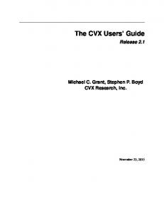
SENTRAN7 now contains a general View File Module in the Main Menu. Users type the name of the file to be viewed (SEN.LOG, for example) and the file will be scrolled on the screen. If the specifed file does not exist, then a file listing of the current directory is given. Note that View File Module converts all file names to upper case, so it cannot be used to see lower case files on Unix systems. Also, any text beyond Column 80 is not shown when the file is listed. An example of a file being listed is shown in Figure 1. Other examples of how to use the View File Module are given in the Users Guide. SENkIAN7 :SUNUNIE VXisb
SPAITA. lm.
SENTRAN7 VIEW FILE UTILITY
VIEMING FILE: I TROPICAL 1 0.000 1.013E+03 2.997E+02 3.200E-01 1.500E-01 1.700E+00 1.580E-01 O.OOOE+00 1.000 9.040E+02 2.937E+02 3.200E-01 1.450E-01 1.700E+00 9.910E-02 O.OOOE+00 2.000 8.050E+02 2.877E+02 3.200E-01 1.399E-01 1.700E+00 6.210E-02 O.OOOE+00 3.000 7.iSOE*02 2.837E+02 3.200E-01 1.349E-01 1.700E+00
NODELI.PRO
33
... MORE...
2.593E+04 2.090E+05 0.OOOE+00 1.949E+04 2.090E+05 0.OOOE+00 1.534E+04 2.09E+05 0.OOOE+00 8.600E+03 2.09E..05
3.300E+02 2.869E-O2AAAAMAAARRAAA 3.OOOE-04 3.OOOE-04 2.300E-05 5.000E-04 0 0 0 0 0 3.300E+02 3.150E-O2AMAAAAAAAAAAA 3.OOOE-04 2.740E-04 2.300E-05 5.000E-04 0 0 0 0 0 3.300E+02 3.342E-O2A AAAAAR AA 3.OOOE-04 2.360E-04 2.300E-05 4.630E-04 0 C 0 0 0 3.300E+02 3.504E-O2AAAAMAAAA AA 3.OOOE-04 1.900E-04 2.300E-05 3.800E-04
HIT TO CONTINUq
Figure 1. Example of a File Listing With SENTRAN7's View File Module
14
2.8 Renaming of Output Files from LOWTRAN7 and MODTRAN Users can now instruct SENTRAN7 to save output files from LOWTRAN7 and MODTRAN as customized file names. This feature is particularly useful because these codes overwrite the files using standard output names (i.e., TAPE7) each time the Run Module is selected within SENTRAN7. Specifically, SENTRAN7 creates customized file names by first identifying the root name of the JNP file and then appending the following extensions: 1. TAPE6 output is copied to root name.TP6 2. TAPE7 output is copied to root name.TP7 3. TAPE8 output is copied to root name.TP8 If the input file generated by SENTRAN7 for LOWTRAN7 and MODTRAN is named SPACEINP, for example, then the output in TAPE6, TAPE7, and TAPE8 output is copied to SPACE.TP6, SPACE.TP7, and SPACE.TP8, respectively. This
feature is exercised from the Run Module (see the Users Guide). 2.9
Optional Display of Absorbing Species
SENTRAN7 now permits users to deactivate the listing of active molecular absorbers in the Compile Module. To do this, users type 'abs' from the Main Menu (see the ABS command in the Users Guide for details). This feature has been added to SENTRAN7 to speed up sensitivity studies that involve wavelength regions with many molecular absorption bands. That is, the process of listing all molecular absorbers can be time consuming, requiring users to hit RETURN many times. 2.10 Improved Method of Perturbation for Card 2C3 Parameters SENTRAN7 now contains an improved algorithm to perturb the IHAl, ICLD1, IVUL1, ISEAl, and ICHR1 parameters on CARD 2C3. Previously, the menu in the Edit Module would only accept percent perturbations for these parameters when, in fact, they are supposed to be set to discrete integer values. Given that the percent perturbations must be less than 100%, any sensitivity study involving the IHA1, ICLD1, IVUL1, ISEAl, and ICHR1 parameters would always be assigned the default values in the PRO file. The Edit Module now accepts integer perturbation values for the IHAL, ICLD1, IVUL1, ISEA1, and ICHR1 parameters (see Section 4.2.3.5).
15
3 INSTALLING AND RUNNING SENTRAN7 3.1 Overview of Software SENTRAN7 is designed to be highly portable, while maintaining a reasonably high level of performance. These goals dictate the use of highly portable code and common standards for graphics and terminal control. Given these requirements, SENTRAN7 is coded in Fortran-77. The code utilizes the Tektronix 4010/4014 format standards for graphics 7 and the American National Standards Institute (ANSI) standard for terminal control. 8 Tektronix 4010/4014 is selected because it is probably the most popular graphics format to be emulated. Moreover, graphics and terminal control kernels in SENTRAN7 are completely self contained, obviating the need for external software libraries. Digital Equipment Corporation's VT240 terminal (along with several VT240 compatibles available from other manufacturers) supports both the ANSI and TEK4010 standards, so it is an ideal terminal for interactive viewing of SENTRAN7 graphics. It is noted that the VT240 is, in fact, one of the industry standard graphics terminals which endorses SENTRAN7's choice of standards. 3.2 Installing the Program Table 2 lists the files included with the SENTRAN7 package. To install the code, first create a subdirectory to contain the programs and data files. Once this has been completed, copy the files from the distribution media into the target subdirectory. SENTRAN7 can be compiled to run on either a VAX/VMSTM system or Sun MicrosystemsTM computer. The following instructions explain how to compile and link SENTRAN7: "*For
a VAX/VMSTM system, type '@makefile'. This creates the executable file
sentran.exe.
a SunTM computer, type 'make'. This creates the executable file sentran. Note that some SunTM computers will generate a series of warning messages during compilation which can be ignored by the user. To start the program, the user simply types 'r sentran' if on a VAX/VMSTM system. On a SunTM computer, SENTRAN7 should be executed from the xterm Tektronix 4014 terminal emulator program, which is part of the X Window System "* For
7 Tektronix, Inc. (1977) Users Guide and Service Manualfor 4014, 4014-1 Terminals, Tek Part No. 070-1647-00, Beaverton, OR. 8 ANSI Standard X3.64 (1979) Additional Controlsfor Use With ASCII, Secretariat: CBEMA,
1828 L St., N.W., Washington, DC.
16
Table 2. Files Included with the SENTRAN7 Package. File listing is for UNIX
systems. Users must change "*.f' extensions to "*for" for VAX/VMSTM systems CONTENTS
FILE NAME senmainf
Source code for SENTRAN7 (main program only)
sensubsf
Source code for SENTRAN7 (supporting routines)
senpert"
Source code for SENTRAN7 (perturbation routines)
senchkj
Source code for SENTRAN7 (error checking routines)
senvms.for
Source code for SENTRAN7 (VAX computer systems only)
senuixf
Source code for SENTRAN7 (UNIX computer systems only)
andor.c
Fortran bit manipulation code (UNIX computer systems only)
MAJABSDAT
Data file defining regions of molecular absorption
DIRECT.ORY
Configuration file containing directory and name of LOWTRAN7 and MODTRAN executables and the UFTAPEDAT file. Curent directory is assumed when DIRECT.ORY does not exist
SENTRANJHLP
SENTRAN7 on-line help utility file
MODEL1.PRO
Tropical atmosphere profile (i.e., Card 2C series)
MODEL2.PRO
Midlatitude summer profile
MODEL3.PRO
Midlatitude winter profile
MODEL4.PRO
Subarctic summer profile
MODELS.PRO
Subarctic winter profile
MODEL•.PRO
U.S. standard profile
SAMPLEAER
Sample Card 2D series: normalized aerosol extinction versus wavelength for four aerosol regions
SAMPLE.PHS
Sample Card 3B series: aerosol phase functions for four aerosol regions
SAMPLE.RND
Sample random perturbations input file
DEFAULT.MTH
Sample methodology file (used in Tutorial #1)
lowtran7f
Source code for LOWTRAN7
modfran.f
Source code for MODTRAN
mkbin.f
Program creates UFTAPE.DAT from BMTAPEDAT
makefile.com
Command file for compiling and linking SENTRAN7 on VAX/VMS systems. Type '@makefile' to execute
makef/e
Unix command file for compiling and linking SENTRAN7 on SUN systems. Type 'make' to execute
17
OpenWindows. To do this, make sure the current path includes the xterm terminal emulator program and type 'openwin' to enter OpenWindows. To execute SENTRAN7, type 'xterm -geometry 80x24 -e sentran'. An xterm window will appear and SENTRAN7 will automatically begin execution. Under xerm, the scrolling features in SENTRAN7 work properly and the user can easily view SENTRAN7 Tektronix plots (see Section 4.2.8.6 for details). 3.3 LOWTRAN7 and MODTRAN Requirements Source codes for both LOWTRAN7 and MODTRAN are included with SENTRAN7. Slight modifications have been made to both source codes in order to run with SENTRAN7. The user is referred to Appendix B for a discussion of the changes. Other than the modifications specified here, no other modifications to either LOWTRAN7 or MODTRAN are allowed if they are to work with SENTRAN7. LOWTRAN7 has been modified to continue layer-by-layer calculations even when the differential transmittance (DTAU) has become very small. In the standard
version of LOWTRAN7, the program would jump out of the calculation loop when DTAU was less than 10-5. For SENTRAN7 however, the complete array of DTAU and flux data must be included in tape8 to avoid empty regions or "gaps" in the 3D plots of DTAU and flux data. For reference, these code changes are given in Appendix B. The code changes to LOWTRAN7 are included with this distribution.
It is worth noting that coding changes for Version 4.2 of LOWTRAN7 (released 2 February 1992) address this DTAU issue. Thus, users who receive updates and errata for LOWTRAN7 may have made the DTAU code changes already. Note
that, the changes made to LOWTRAN7 are recommended changes, but are not required to run LOWTRAN7 with SENTRAN7. MODTRAN has been similarly modified in order to continue layer-by-layer calculations even when D'T-AU has become very small. In addition, because the input structure for MODTRAN is slightly different from LOWTRAN7, MODTRAN
must be modified slightly to work with SENTRAN7. For reference, these code changes are also given in Appendix B. The modified version of MODTRAN is included as part of the SENTRAN7 package (modtran-f). Note that the changes made to MODTRAN are reuire in order for MODTRAN to work with SENTRAN7. Using the DIRECT.ORY File The DIRECT.ORY file allows users to specify the directory where the executable codes for LOWTRAN7 and MODTRAN reside. A sample DIRECT.ORY file has been included with the SENTRAN7 package. SENTRAN7 uses this file to locate the executable code for the transmission model chosen by the user. The 3.4
18
file, DIRECT.ORY, should be edited with a standard text editor on the user's computer system to indicate the directories and names of the executable codes for LOWTRAN7 and MODTRAN, as well as the location of MODTRAN's molecular absorption data file called UFTAPE.DAT. Note that, if DIRECTORY does not exist, SENTRAN7 searches the current directory for the appropriate files. 4 USERS GUIDE FOR SENTRAN7 This users guide is targeted at both novice and experienced SENTRAN7 users, and provides an overview of SENTRAN7's structure and usage. Details of command usage in a quick reference format, may be found in Appendix C. Recall that SENTRAN7 can execute either LOWTRAN7 or MODTRAN. Unless explicitly stated, the use of the term MODTRAN will imply reference to both LOWTRAN7 and MODTRAN. Overview of SENTRAN7 A brief overview of SENTRAN7 is given in this section for users who are not familiar with the original SENTRAN code. Users who are familiar with the features of the original SENTRAN may skip this section and proceed to Section 4.2. 4.1
4.1.1 Code Philosophy SENTRAN7 is a general purpose computer code that facilitates the analysis of MODTRAN's response to the perturbation of its input parameters. SENTRAN7 is primarily designed as a comfortable, interactive interface to MODTRAN with special provisions for perturbation analysis. Using SENTRAN7, one can easily extract, analyze, reduce, and plot MODTRAN output. These features permit users to rapidly perform analyses that would be difficult or impossible through bruteforce techniques. The process is highly automated and requires little effort on the part of the user because SENTRAN7 is "intelligent" enough to keep track of the details of parameter variation. Also, SENTRAN7 contains many useful analysis tools such as evaluating partial derivatives of a variable represented by the z axis with respect to two independent variables given by the x and y axes. Using these capabilities, users can rapidly determine those regions where MODTRAN's calculations are most sensitive. SENTRAN7 makes extensive use of graphics to display results. The human eye possesses strong abilities with respect to trend analysis and can identify complicated patterns at a glance. These capabilities are fully exploited in SENTRAN7 via the use of 3D surface plots, enabling users to visualize MODTRAN's response to the simultaneous variation of two parameters. These plots can be archived as files for hard-copy generation and/or later perusal on a graphics terminal. 19
4.12 Design Criteria The design of SENTRAN7 was based on the following general criteria: 1. User friendliness 2. Framework for sensitivity analyses 3. 4. 5. 6.
High portability Quick turnaround time for interactive analyses Extensive use of graphics for data presentation Provisions for data analysis and reduction tools.
User friendliness is one of the single greatest considerations in SENTRAN7's design. Most of SENTRAN7 is devoted to providing users with a comfortable working environment, without compromising flexibility or power. User friendliness is implemented in a number of ways, including: 1. The code is virtually crash proof, using character oriented input for command strings and numerical values. Before being accepted, numerical inputs are examined to make sure they are physically meaningful. 2. Commands can be entered in upper, lower, or mixed case. 3. Abundant feedback is provided, including step-by-step prompts and ample information when the code cannot properly read user-specified input files. 4. The command interpreter can resolve the component parts of complicated input strings, bypassing input prompts, thus permitting veteran users to use the code with increased speed. 5. Sensible defaults are provided wherever possible, reducing the chance of
erroneous input. 6. On-line help is available, minimizing the amount of time required to learn how to use SENTRAN7. The help feature also provides information on MODTRAN inputs. While this list is by no means complete, it provides an idea of the user friendly features of SENTRAN7. Collectively, these features eliminate the need to concentrate on file and data manipulation so users can focus on the scientific aspects of their MODTRAN analysis problems. Another important requirement is the ease and speed of post-processing of MODTRAN outputs. SENTRAN7 tries to isolate MODTRAN from the user as much as possible so that the user need not be aggravated by bookkeeping. It can extract transmittance and/or radiance data from MODTRAN's tape7 and tape8 output files. Also, SENTRAN7 is intelligent enough to prompt the user with the
20
list of input parameters that can be chosen as independent variables for plotting and derivative computation. Data analysis and reduction tools are provided along with graphics in an interactive module. The analysis tools include common data manipulations such as logarithmic transformation of data and partial derivatives of first and second order with respect to the independent axes. Furthermore, SENTRAN7 can read and plot raw data files as well as output the reduced data as raw data files for use in commercial plotting packages.
4.2 Program Structure SENTRAN7 is structured into a number of subprograms called modules. Each module performs a specific task to aid users in their sensitivity studies. The modules are ordered according to the way users would typically conduct a sensitivity study. The seven main modules of SENTRAN7 are listed in Table 3. The SENTRAN7 Main Menu is shown in Figure 2. The following sections provide specific details on how to use each of the SENTRAN7 modules. 4.1 Help Module On-line help is available at almost all locations within the SENTRAN7 program. Specifically, help information is available at the Main Menu, within the Edit Module, and within the Graph & Analyze Module of SENTRAN7. At the Main Menu, users can obtain general information about most of SENTRAN7's modules listed in Table 3. To access this information, the user enters the command 'help' followed by a module name from the Main Menu Screen. For example, the user could enter 'help load' for a description of the LOAD command. In the absence of a module name, an introductory help screen appears which displays a list of help topics (see Figure 3). Users can then enter the name of a selected topic, whereupon they will receive help on that particular topic. If the user does not select a topic, or selects an invalid topic, control will return to the Main Menu. On-line help is also available in the Edit Module and the Graph and Analyze Module of SENTRAN7. These on-line help capabilities are described in greater detail in Sections 4.2.4.6 and 4.2.8.5, respectively. 4.2.2 Load/Save Module In SENTRAN7, images of MODTRAN input parameters and commands for their perturbation are contained in files known as "methodology" files. These files are stored on the host computer with .MTH extensions. Methodology files enable users to store various methodologies and use them as starting points for new calculations. A more detailed description of a methodology file is given in Appendix A. 21
Table 3. List of SENTRAN7 Modules MODULE Help Load/Save Define Perturbations Edit Compile Select Run Graph and Analyze View Fide
WJ LOS ON
MAIN FUNCTION Provides help for SENTRAN7 users Loads and saves SENTRAN7 methodology files Defines deterministic and random perturbation parameters for atmospheric variables in the Card 2C series Permits users to define their MODTRAN problems, including atmospheric inputs and commands for their perturbation Creates MODTRAN input file based on editing session and displays major molecular absorbers Selects code to be used: LOWIRAN7, MODTRAN or MODTRAN run as LOWTRAN7 Executes selected code, and creates MODTRAN's tape7 and tape8 files Extracts output data, analyzes and graphs, and reduces data I/O Views files without exiting SENTRAN7
SENTRA7: SUN.UNDX VWsioa
SPARTA
c. M
WECONE TO SENTRAN7
THE SENSITIVITY ANALYSIS PROGRAN FOR LOUTRAN7/NOOTRAN I - LOAD/SAVE 2 - DEFINE PERTURBATIONS 3 - EDIT 4 - COMPILE S - SELECT LOUTRAN7/NODTRAN 6 - RUN HOOTRAN 7 - GRAPH & ANALYZE 8 - HELP 9 - VIEU FILE
'41
10 - QUIT
Figure 2. Display of the SENTRAN7 Version 2.0 Main Menu 22
NUNE9 Vwsia
53fTUAW: SU
SENTRAU
OSLIN
SPARTA. bg.
HE .P UTILITY
HELP IS AVAILABLE ON THE FOLLOVING TOPICS EFINE
EDIT
LOAI
SAVE
SELECT
RUN
GRAPH
ANALYZE
VIEi
SEARCH
ZAP
LOG
COPII.E
ABS
ENTER THE NAME OF THE SUBJECT FOR MIUCH YOU NEED HELP OR PRESS TO RETURN TO MAIN PROGRAM NOTE:
THE HELP COHIWID ACCEPTS THE ABOVE ITEMS AS ARGUMENTS. BYPASSING THIS SCREEN EXAMPLE: HELP EDIT
HELP i
Figure 3. The Introductory Help Screen in the Help Module The Load/Save Module is where users load and save selected methodology files. To load a methodology file, the user enters '1' or 'load' at the Main Menu prompt. If the user enters '1', SENTRAN7 will ask the user whether they want to load or save a methodology file. The user then enters 'load' or simply 'T', in order to load a file. The program will then display a list of all files with a MTH extension present in the current directory and will prompt the user for the file name to load. if the user knows which methodology file they wish to load at the Main Menu, several steps can be saved by simply entering 'load filename' at the Main Menu prompt, where filename is the name of the methodology file to be loaded. Recall that a .MTH extension is presumed on methodology files unless the user specifies a different extension. For example, typing 'load example' will load a file named EXAMPLE.MTH, while typing 'load wierd.ext' will load a file named WIERDZEXT. Similarly, if the user wishes to save the current values of all the parameters set within the Edit Module, to a methodology file, the user enters '1' or 'save' at the Main Menu prompt. If the user enters '1', they must then choose the save option. The user is then prompted for the name of the methodology file to save the current parameter values in. This file is also given a MTH default extension unless a different extension is specified by the user. If the file already exists, the user must confirm that the file is to be overwritten. If the user enters 'n', program control will be returned to the Main Menu and the methodology file will not be overwritten. Saving methodology files allows the user to easily restore the parameters used for 23
a given simulation. It is worth noting that the current values of the parameters set within the Edit Module are saved to a special file, LAST.MTH, after every completed editing session (i.e., an editing session in which the user does not proceed to the Main Menu via the END command) and after every compilation. Ibis file is loaded into SENTRAN7 at the beginning of the next SENTRAN7 session and provides a default methodology for the session. Therefore, users are cautioned against saving methodology files named LAST.MTH, or tampering with the LAST.MTH file in any way. 4.2.3 Define Perturbations Module The Define Perturbations Module is a new feature in SENTRAN7 in which users can specify deterministic and random pertubation parameters for their sensitivity studies. The parameters in this module apply to sensitivity studies with user-defined atmospheric profiles (i.e., the Card 2C series). Thus, users must have defined a LOWTRAN7 or MODTRAN problem with MODEL=7 on Card 1. Specifically, users can impose deterministic and random perturbations on layer-by-layer values of: 1. Pressure 2. Temperature 3. Water vapor 4. Other gas constituents 5. Aerosol vertical scaling factors 6. Equivalent water contents 7. Rain rates. Within the SENTRAN7 framework, user-defined atmospheric profiles are stored in files that must be created off-line by the user. The default extension of these files is PRO. To select the Define Perturbations Module, the user simply types '2' or 'define' at the Main Menu command line. The Define Perturbations submenu then appears, as shown in Figure 4. 4.2.3.1
Overview
The basic scheme to include deterministic and random perturbations in a SENTRAN7 sensitivity study is a two-step process. Users must first define the appropriate parameters for a deterministic or random perturbation study in the Define Perturbations Module and then activate these perturbations for an atmospheric variable within the Edit Module. Additionally, users must select a random number 24
1W13*W t SOMMM Vwsm fte.a~
SENTRAM7
WDTN
UTILITY
TWG TYPES OF PERTURBATIONS ARE AVAILABLE IN SENTRAN7.
INVOKE THESE PERTURBATIONS FOR CARD 2C PARAMETERS IN THE EDIT MODULE BY TYPING RANi.
RAN2. DETI. DET2.
SELECT THE TYPE OF PERTURBATION: PERTURBATIONS
1
-
RAPOM
2
-
DETERMINISTIC PERTURBATIONS
3
-
EXIT TO WAIN MENU
?
Figure 4. Display of the Define Perturbations Submenu generation scheme when the random perturbation option is used. In the subsections to follow, the scheme to specify and activate deterministic and random perturbations is described, although the full procedure involves user actions in the Define Perturbations Module and the Edit Module. 4.2.3.2
Define Deterministic Perturbations Option
To define deterministic perturbations, type '2' at the Define Perturbations submenu, as shown in Figure 5. The menu to define the first set of deterministic perturbations then appears, as shown in Figure 6. Here, users can then enter percent perturbations for the layers of their choosing. To move around in this menu, users can use the cursor control commands from the Edit Module. (See Section 4.2.4.2 and Table 6 for a detailed description of the cursor control commands. Also, recall that all cursor control commands and percent perturbations must be followed by a RETURN.) For example, if users want to perturb the 6th layer by 10%, this can be achieved by entering 'dn 5' and then '%10'. Note that layers with no percent perturbations will not be perturbed. After specifying percent perturbations by layer, users can type 'pd' which causes users to confirm their inputs, as shown in Figure 7. If 'y' is entered, SENTRAN7 displays the menu to define the second set of deterministic perturbations. Here, users can enter additional layer-by-layer percent perturbations, if desired. Note that the user does not have to use both sets of deterministic perturbations. To return to the Main Menu, type 'end'. 25
IINUA:
SVU
SMIrr.
Vml•m
SENlAN7 EDITING UTILITY TUG TYPES OF PERTUATIONS ARE AVAILLE IN SENTmE7. INVOKE THESE PERTURBATIONS FOR CARO 2C PRANETERS IN THE EDIT NODULE BY TYPING RANi1. RAN2. OETI. DET2.
SELECT THE TYPE OF PERTURBATION: 1 - RANDOM PERTURBATIONS
2 - DETERMINISTIC PERTURBATIONS 3 - EXIT TO MINE IENU
Figure 5. Example of the Command Used to Define Deterministic Perturbations
SENTRAN7 : SUNFUNl
SPARTA, SiM.
VWiSJ6
sE~nRN7 EDITIN
UTILITY
DEFINE FIRST DETERNINISTIC PERTURBATION
ETE LAYER 2 3 4 5 6 7 8 9 10 11 12
*
ANT
PERTURBATION FOR ANY LAYER(S) LAYER
13
%ANT
14 1s 16 17 18 19 20 21 22 23
LAYER
24
Z ANT
25 26 27 28 29 30 31 32 33 34
Figure 6. Menu to Define the First Set of Deterministic Perturbations. A similar menu is available for the second set of deterministic perturbations 26
4.2.3.3
Define Random Perturbations Option
To define random perturbations, type '1' at the Define Perturbations submenu, as shown in Figure 8. The menu to define random perturbations then appears, as shown in Figure 9. Note that the menu contains parameters to generate two random perturbation profiles. The meaning of these parameters and their allowable values are given in Table 4. To move around in this menu, users can use the cursor control commands from the Edit Module. (Recall that all cursor control commands and numerical inputs must be followed by a RETURN.) In Table 4, the parameters NPERT1 and NPERT2 tell SENTRAN7 how many randomly perturbed profiles to generate. Currently, the first randomly perturbed profile is set to the mean profile because SENTRAN7 must retain it for use as the nominal profile. If NPERT1=5, for example, SENTRAN7 will generate five profiles, but the first profile is the mean profile. Note that if a sensitivity problem is compiled with the NOMESH option, the LOWTRAN7 and MODTRAN run with the mean profile is placed last in the perturbation sequence which is consistent with the original programming structure of SENTRAN. In Table 4, the parameters RFLG1 and RFLG2 determine the source of the standard deviation and correlation length data (i.e,, a(z) and L(z)). For clarity on this issue, SENTRAN7 only allows users to specify SIGMAl and LI when RFLGI=0. Similarly, SENTRAN7 only allows users to specify files of Uf(z) and L(z) when RFLGl=7. The default extension for these files is .RND and the file format is given in Appendix A. Also, it is worth mentioning that the random perturbation menu is used to specify both correlated and uncorrelated random perturbation types. To simulate uncorrelated perturbations when RFLGl=O, users must set LI equal to zero. To simulate uncorrelated perturbations when RFLG1=7, users must set the values of L(z) in the .RND file equal to zero. After specifying the parameters to generate random perturbation profiles, users should enter 'pd' which causes use's to confirm their inputs, as shown in Figure 10. If 'y' is entered, then SENTRAN7 will prompt users for random number information which is discussed in the next section. 4.2.3.4
Select a Random Number Generator for Random Perturbations
The random perturbation technique used by SENTRAN7 requires the generation of a random variable with a mean = 0 and variance = 1. Currently, the SENTRAN7 uses the random number generator from the Numerical Recipes Library 9 . This set of routines makes use of an integer seed that serves the following purposes: 9 Press, W.H., Flannery, B.P., Teukolsky, S.A. and Vetterling, W.T. (1986) Numerical Recipes, Cambridge University Press, New York, NY.
27
SJiTRAX: SWUVM/ui Vessie.
SNRM
EDITING UTILITY
SPARTA, lao.
DEFINE FIRST DETERMINISTIC PERTURBATION ENTER Z PERTURBATION FOR ANY LAYER(S) LAYER 2 ANT 1 2 3 4 5 6 2L0 7 8 9 10 11 12
LAYER 13 14 15 16 17 18 19 20 21 22 23
Z ANT
LAYER 24 25 26 27 28 29 30 31 32 33 34
X ANT
FIRST DETERMINISTIC PERTURBATION O.K. (Y/N) 113
Figure 7. Example of the Final Screen Displayed After Defining the First Set of Deterministic Perturbations. In this example, the user opted to perturb the 6th layer by 10%
Lii
SENTIRAN7: SUWUNtPIE Vwzies
SPARTA, IIm
SENTRAN7 EDITING UTILITY T1O TYPES OF PERTURBATIONS ARE AVAILABLE IN SENTRAN7. INVOKE THESE PERTURBATIONS FOR CARD 2C PARAMETERS IN THE EDIT NODULE BY TYPING RANI. RAN2. DETI. DET2.
SELECT THE TYPE OF PERTURBATION: I - RANDOM PERTURBATIONS 2 - DETERMINISTIC PERTURBATIONS 3 - EXIT TO MAIN MENU
Figure 8. Example of the Command Used to Define Random Perturbations
28
8 $ETAW:$ $
Eft VwS sa
SMfUTAIm1.
SENTRAN7 EDITINS UTILITY DEFINE RANDOM PERTURBATION PARAMETERS ALL PARAMETERS TAKE ONE VALUE FIRST RANDOM PERTURBATION: 2 WERT1 0 RFLG1
25
SIUIAI
10.000 1140 FILENANE FOR SINK AND RHOI PROFILE C.tI)]
SECOND RANDOM PERTURBATION (OPTIONAL): 0 NPERT2 0 RFL62
SIUIA2 R102
0.000
FILENAME FOR SIGNA2 AND R.12 PROFILE
.R)]
Figure 9. Menu Displayed to Define Correlated and Uncorrelated Random Perturbations Table 4. Summary of Parameters Used to Define Random Perturbations RANDOM PERTURBATION PARAMETER NPERT1 RFL•1 SIGMAI
POSSIBLE VALUES FIRST 1-10 0 or 7 > 0*
MEANING RANDOM PERTURBATION Number of random profiles to generate Source of correlation length and standard deviation data Height independent standard deviation
(used if RFLG1=0) Li
> 0
Height independent correlation length
(used if RFLG1=0) Filename
File of layer-by-layer standard deviations and correlation lengths
(used if RPLG1=7) NPERT2 RFLG2
SECOND 1-10 0 or 7
SIGMA2
> 0
L2
>0
Filename
RANDOM PERTURBATION Number of random profiles to generate Source of coreation length and standard deviation data Height independent standard deviation (used if RFLG2=0) Height independent correlation length (used if RFLG2=0) File of layer-by-layer standard deviations and correlation lengths
(used if RFLG2=f7) * Expressed as a percentage (i.e., "%10") or an absolute magnitude (i.e., "123.456")
29
SENTMAN: ISUV•UIM
Vasm
SE"NTRlAN7 EDITI/NG UTILITY
SMfATA, it.
OEFINE RANM PERTW8ATION PARAMETERS ALL PAMUETERS TAKE ONE VALUE FIRST RNDOM PERTURBATION: NPERTI
2
RFL61 0 SIGNA1 2 RMO 10.000 FFIEM FOR SIMIAI All) RHOI PROFILE [.ION SECOND RANDOM PERTURBATION (OPTIONAL): NPERT2
0
RFLG2
0
RM02
0.000
FILENWE FOR SIGHA2 AND RMH2 PROFILE [.IND] ALL PARAMETERS O.K.
(Y/N)
E13
Figure 10. Example of the Final Screen Displayed After Defining Random Perturbations. In this example, the user has opted to define random perturbation parameters for the first atmospheric variable only 1. A fixed positive seed generates the same sequence of random numbers 2. Different positive seeds generate different sequences of random numbers 3. A negative seed restarts the random sequence. SENTRAN7 allows users to select from two types of random number sequences for correlated and uncorrelated random perturbation profiles. These are: 1. Reinitialize the random number sequence 2. Use fully random numbers. The first option is often desirable because it allows users to duplicate their sensitivity studies from different SENTRAN7 sessions. The second option is acheived in SENTRAN7 by means of a system call to the computer clock which provides a positive variable seed. The menu to select the type of random number sequence, which is shown in Figure 11, automatically appears immediately after a user defines the random perturbation parameters. Users should type '1' to reinitialize the random number sequence and '2' to use fully random numbers. Once a random number sequence has been selected, it will be used in all subsequent compilations to generate random perturbation profiles, until another random number sequence is selected.
30
$1ffiW: SWUNI Veae
SfA9TA. 1w.
SENIRMI7 EDITING UTILITY RUSON PERTUIRATIONS REQUIRE A SEQUENCE OF RANDOM UMBERS. RESTARTING TIE RANDOM NUNBER GENERATOR CAN BE USED FOR REPEATUILITY PURPOSES.
RDI)ON NUBERS ARE GENERATED: SPECIFY HMOU
I - RESTART RANON OUINBER GENERATOR SEQUENCE 2 - FULLY RANOON NUMBER SEQUENCE
Figure 11. Menu Used to Select the Random Number Sequence To Be Used When Generating Correlated and Uncorrelated Random Perturbation Profiles. In this example, the user has opted to restart the random number generator 4.2.3.S
Invoke Deterministic and Random Perturbations
To invoke deterministic and random perturbations, the user must enter SENTRANT's Edit Module and define the sensitivity problem. (Recall that in order to make use of deterministic and random perturbations, a user must employ a user-defined atmosphere. This class of problems requires MODEL=7 on Card 1.) Specifically, the place to invoke deterministic and random perturbations is in the Edit Card 2C menu, immediately after having specified the file name for userdefined atmospheric profiles (i.e., the PRO file). Users must first proceed to the atmospheric variable that they want to impose the perturbations on. To invoke deterministic perturbations, enter 'detl' for the first deterministic perturbation or 'det2' for the second deterministic perturbation. Similarly, to invoke random perturbations, enter 'ranl' for the first random perturbation or 'ran2' for the second random perturbation. Examples of the commands to impose the first deterministic and random perturbations on temperature are shown in Figures 12 and 13, respectively. After typing 'detl', 'det2', 'rani', and 'ran2' for the desired atmospheric variables, users can continue with their SENTRAN7 session. At this point, it is worth mentioning that SENTRAN7 allows users to repeat 'detl', 'det2', 'rani', and 'ran2' for more than one atmospheric variable in the Edit Card 2C menu, in order to impose the same deterministic or random perturba31
SSIENTRAW:
SWU*U WOsOS
SPARTA. "Mr.
SENT7 EDMMIN5 UTIITH y EDITING CARD 2C FOLLOMING PARNIS ACCEPT ONLY Z PERTURBATIONS ZNDL P... T... H20 C02 03
OETI
a EQLiCZ RRATZ il4L CLDI IVULi ISEA1 TCHlR.
N20 Co CH4 02 NO S02 N02 NH3 HN03
Figure 12. Menu Showing the Command Used To Invoke Deterministic Perturbations on the Edit Card 2C Menu. In this example, the user has opted for the first deterministic perturbations on temperature
M
SUNTIAN? :SUN4/UrX Vmsie
SPARTA. Imw.
SENTRAN7 EDITING UTILITY EDITING CARD 2C FOLLOMING PARAMIS ACCEPT ONLY Z PERTURBATIONS ZHOL P... T... HMO C2 03
RW lIi
MHAZE EQLI.CZ RRATZ IM*
N20 CO CH,4 02 NO S02 N02 NM3 HN03
IVUL1 ISEA. ICHRI
Figure 13. Menu Showing the Command Used To Invoke Random Perturbations. In this example, the user has opted for the first random perturbations on temperature 32
tion parameters. However, the percent perturbation amounts for two atmospheric variables with the same 'ranl', or 'ran2' command will differ layer-by-layer because they access different portions of the random number sequence. Also, note *that users can still enter a percent perturbation in this menu, in order to perturb all layers by the given percentage. 4.2.3.6
Files With Deterministic and Random Perturbation Profiles
SENTRAN7 provides the means to create files that contain deterministic and random perturbation profiles. The standard 'write' command, which creates a 3D file in the Edit Card 2C menu, is available for deterministic perturbations after users have entered 'deti' or 'det2' for an atmospheric variable. The procedure is the same as that for percent perturbations (see Section 4.2.9). The root names for the 3D files with deterministic perturbations are the same as those for the standard
'write' command. Because the generation of random perturbation profiles only takes place in SENTRAN7's Compile Module, the 'write' command has been disabled for random perturbations after users have entered 'rani', or 'ran2' for an atmospheric variable. As a replacement, SENTRAN7 automatically tabulates these values in a fixed file named RANDOMI.DAT whenever a compile command is issued. SENTRAN7 also provides a statistical analysis of randomly perturbed profiles so users can decide if the code has matched the desired specifications within allowable tolerances. Specifically, SENTRAN7 calculates the mean, standard deviation, percent standard deviation, and correlation length of the randomly perturbed profiles as a function of altitude. The results are automatically tabulated in a fixed file named RANDOM2.DAT whenever a compile command is issued. Table 5 gives a summary of files that contain deterministic and random perturbation profiles. Table 5. General Information About Files That Contain Deterministic and Random Perturbation Profiles DETERMINISTIC PERTURBATIONS
RANDOM PERTURBATIONS
'write' Command File Nane
Yes 3D
Creation of File Time of Creation
Optional At 'write' command
No RANDOM1.DAT (Perawbation Profiles) RANDOM2DAT (Statistical Analysis) Always During compilation
An example of output written to RANDOMI.DAT is shown in Figure 14. If a sensitivity study has more than one randomly perturbed atmospheric variable,
33
additional profiles are appended at the bottom of RANDOMI)DAT. Note that RANDOM).DAT is overwritten each time a compile command is performed. Thus, the contents of RANDOM).DAT represent the most recent .NP file to be created. The contents of RANDOM).DAT cannot be plotted in SENTRAN7's Graph & Analyze Module. An example of output written to RANDOM2.DAT is shown in Figure 15. If a sensitivity study has more than one randomly perturbed atmospheric variable, additional analyses are appended at the bottom of RANDOM2.DAT. Also, note that RANDOM2.DAT is overwritten each time a compile command is performed. Consequently, the contents of RANDOM2 DAT represent the most recent JNP file to be created. The contents of RANDOM2.DAT cannot be plotted in SENTRAN7 's Graph & Analyze Module. Note that statistical analysis always corresponds to the randomly perturbed profiles in RANDOM1.DAT. 4.2.3.7
Restrictions in the .PRO File
To apply deterministic and random perturbations to an atmospheric variable, layer amounts in the .PRC file must be defined numerically. That is, the user cannot specify model atmosphere values (i.e., 1,2,3,4,5,6) in the JCHAR character array because these values override the numerical input (see the Users Guide for LOWTRAN7). Additionally, all layer amounts for the atmospheric variable should be specified using the same physical units when the random perturbation option is desired. It is the users responsibility to ensure that these conditions are satisfied. 4.2.3.8
Limited Consistency Checks
It is worth emphasizing that deterministic and random perturbations are directly applied to the .PRO file that is specified in the Edit Module. Currently, SENTRAN7 performs no "cross checking" of a PRO file from the Define Perturbations Module. Consequently, a deterministic perturbation for the 30th layer will not be used if the PRO file only has 25 layers in it. Similarly, when altitude dependent correlation lengths for random perturbations are specified by means of a file with a AZND extension (see Section 4.2.3.3 and Appendix A), the number of layers in the AZND file must match those in the PRO file. Also, the units of L(z) must be Iam and the units of u(z) must match those in the .PRO file for the atmospheric parameter to be perturbed. It is the users responsibility to ensure that these conditions are satisfied.
34
0.000 2.99"1+02 3.024E+02 3.061E+02 2.986E+02 3.021E+02 1.000 2.937E+02 2.952E+02 2.899E+02 2.929E+02 2.867E+02 2.000 2.87TE+02 2.855E+02 2.878E+02 2.833E+02 2.8586+02 3.000 2.8374+02 2.839E+02 2.8621+02 2.861E+02 2.821E+02 4.000 2.770E+02 2.8013+02 2.775E+02 2.804E+02 2.808E+02 6.000 2.703E+02 2.718E+02 2.698$+02 2.7353+02 2.670E+02 6.000 2.6361+02 2.649E+02 2.639E+02 2.612E+02 2.612E+02 7.000 2.570E+02 2.5943+02 2.5971+02 2.547E+02 2.569E+02 8.000 2.5031+02 2.514E+02 2.530E+02 2.520E+02 2.4861+02 9.000 2.436E+02 2.440E+02 2.4623+02 2.389E+02 2.4571+02 10.000 2.370E+02 2.3543+02 2.358E+02 2.386E+02 2.373E+02 11.000 2.301E+02 2.330E+02 2.291E+02 2.318E+02 2.311E+02 12.000 2.236E+02 2.205E+02 2.198E+02 2.227E+02 2.211E+02 13.000 14.000 15.000 16.000
2.170E+02 2.103E+02 2.0371+02 1.970E+02
2.151E+02 2.1141+02 2.0311+02 1.999E+02
2.1753+02 2.055E+02 2.054E+02 1.999E+02
2.176E+02 2.119E+02 2.0671+02 1.951E+02
2.181E+02 2.091E+02 2.017E+02 2.003E+02
17.000 1.948E+02 1.970E+02 1.9471+02 1.947E+02 1.948E+02 18.000 1.988E+02 1.985E+02 2.0001+02 1.9671+02 1.979E+02 19.000 2.0271+02 2.026E+02 2.0081+02 2.029E+02 2.037E+02 20.000 2.067E+02 2.063E+02 2.079E+02 2.0571+02 2.077E+02 21.000 2.107E+02 2.125E+02 2.109E+02 2.126E+02 2.134E+02 22.000 2.146E+02 2.125E+02 2.138E+02 2.157E+02 2.133E+02 23.000 2.1701+02 2.140E+02 2.1843+02 2.1871+02 2.164E+02 24.000 2.192E+02 2.220E+02 2.1961+02 2.210E+02 2.215E+02 25.000 2.214E+02 2.235E+02 2.2111+02 2.234E+02 2.1951+02 30.000 2.3231+02 2.328E+02 2.349E+02 2.336E+02 2.299E+02 35.000 2.431E+02 2.465E+02 40.000 2.5401+02 2.538E+02 "45.000 2.648E+02 2.6433+02 50.000 2.7021+02 2.704E+02 70.000 2.1891+02 2.1843+02 100.000 1.907E+02 1.8961+02
2.419E+02 2.5791+02 2.6471+02 2.718E+02 2.212E+02 1.8971+02
2.408U+02 2.559E+02 2.6821+02 2.688E+02 2.229E+02 1.9181+02
2.458E+02 2.5771+02 2.694E+02 2.7171+02 2.2513+02 1.874E+02
Figure 14. Example of the RANDOM1.DAT File Which Contains Tabulated Values of Randomly Perturbed Profiles. In this example, temperature was perturbed and five profiles were generated. The first column is altitude as defined in the PRO file and the other columns are perturbed profiles where the first profile is the reference profile As mentioned in Section 2.6.3, users must exercise caution when they perturb pressure and/or temperature profiles with the 'detl', 'det2', 'ranr', and 'ran2' commands. That is, altitude, pressure, and temperature are related by the hydrostatic relationship and, consequently, perturbing pressures while holding temperatures at their reference values (or vice versa) is not strictly correct. Therefore,
it is recommended that users only specify small perturbations so departures from hydrostatic equilibrium are relatively minor.
35
SENTRAN? AnuLSIS OF PROFILES WITH RANDD
PERTURBATIONS
NUMBER OF PERTURERD PROFILES (EXCLUDING REFERENCE PROFILE):
ALTITUDI 0.000 1.000 2.000 3.000 4.000 5.000 6.000 7.000 8.000 9.000 10.000 11.000 12.000 13.000 14.000 15.000 16.000 17.00 18.000 19.000 20.000 21.000 22.000 23.000 24.000 25.000 30.000 35.000 40.000
"4.000 50.000 70.000 100.000
AVERAGE OF REFERENCE PERTURBATIONS PROFILE 3.0201+02 2.9572+02 2.9122402 2.9371402 2.8771402 2.866E+02 2.846E+02 2.8371402 2.7971402 2.7701402 2.7051402 2.7031402 2.6281402 2.6361402 2.5771402 2.5701402 2.513E+02 2.503E402 2.4371402 2.436U402 2.3681402 2.3701402 2.3131402 2.3011402 2.2101402 2.236E402 2.1701402 2.1711402 2.095E+02 2.103E402 2.0421402 2.03714+02 1.988E+02 1.9701402 1.953E402 1.9481402 1.983E+02 1,9881402 2.025E+02 2.027E402 2.0691402 2.0471402 2.1231402 2.1071402 2.138E402 2.1460402 2.1691402 2.1701402 2.210E402 2.1921402 2.2191402 2.214E402 2.3231402 2.3281402 2.4371402 2.431E402 2.563E402 2.540E402 2.6671402 2.648E402 2.7071402 2.7021402 2.2191402 2.189E+02 1.8961402 1.9071402
STD DIV OF PERTURBATIONS 2.6420400 3.686E+00 1.834E+00 1.9501400 1.521E400 2.789E400 1.8901+00 2.352E400 1.889E400 3.340E+00 1.4471400 1.6412+00 1.2351+00 1.3271400 2.944E+00 2.2521400 2.444E400 1.1201+00 1.3991400 1.233E+00 1.094E+00 1.0331400 1.360E400 2.155E400 1.041E400 1.9281400 2.1181400 2.831E400 1.890E400 2.51TE400 1.392E400 2.835E400 1.7T941400
4
lOOD.ATIO OF STD DRY/AVERAGE 0.875 1.266 0.642 0.685 0.544 1.031 0.719 0.913 0.752 1.371 0.611 0.710 0.559 0.611 1.405 1.103 1.229 0.574 0.706 0.609 0.529 0.487 0.636 0.994 0.471 0.869 0.910 1.162 0.737 0.944 0.514 1.278 0.946
Figure 15. Example of the RANDOM2.DAT File Which Contains a Statistical Analysis of Randomly Perturbed Profiles. In this example, temperature was perturbed and five p-rofiles were generated. Note that the reference profile is shown in the file, but it is not included in the analysis
36
4.±4 Edit Module The Edit Module of SENTRAN7 provides a flexible means of defining MODTRAN input cards. The SENTRAN7 editor permits the entry of atmospheric data and commands for data perturbation. The user is reminded that MODTRAN's input philosophy is based on "cards" of data. Each "card" relates to data or operating conditions of a specific type. SENTRAN7 retains the MODTRAN input card philosophy and SENTRAN7's editor emulates MODTRAN's logical flow through the input card images. 4.±4.1 General Information To enter the editor, the user should enter '2' or 'edit' at the Main Menu prompt. The SENTRAN7 Edit Module then provides the user with a series of screens from which the user can set up or edit the simulation conditions. Figure 16 provides an example of a screen displayed while editing a MODTRAN "card." The example is for Card 1 of the MODTRAN input cards. The name of the current card image appears at the top of the editing screen, while the name of the MODTRAN input variables appear along the left hand column. Values for each of the MODTRAN inputs appear to the immediate right of the list of names, along with any perturbation instructions. The terminal's cursor will appear to the left of the variable which is currently being edited, and data entry is accomplished by typing over the current field. In Figure 16, MODEL is the parameter currently being edited. Variables that are marked with an "'" are subject to certain restrictions. The input parameters marked with an "'" in the Edit Module, cannot be perturbed in some cases because
their perturbation creates different flows through the input card images. 4.±4.2 Movement in the Edit Menus In the Edit Module, the user hits RETURN to move down the current card image, line-by-line. In addition, there are several input strings that SENTRAN7 reserves for cursor control. These commands are listed in Table 6. Note in Table 6, that the "n" values are optional, and their absence implies n=l. While in the Edit Module, the user can use the UP command to go back to a previous parameter. Simply typing 'up' and RETURN will move the cursor up one line. Tl move back more than one line, the user should enter 'up' and the number of lines to move. For example, the command, 'up 2', will move the cursor back two lines. Similarly, to move ahead, the user should enter the "down" command, 'dn', and the number of lines to move down (if greater than one). If the user has made all the necessary changes to a card and wants to move quickly to the next card image, the PAGE DOWN command, 'pd', is used. Before proceeding to the next card image, the user will be prompted to check that all the parameters on the current card have been set as desired. Similarly, if the user 37
v~aný.
= a V.MICumw LIU
IZULU
(A
WZCU=(
ffrjxcrzOU)
0 :521
S~0 0o *
.....
0
0 0 0 00 0 0
1xa3. = 0.000 0.000
A
wz
Figure 16. Example of a SENTRAN7 Editing Screen for MODTRAN Card 1
Table 6. List of Cursor Control Commands in the Edit Module of SENTRAN7 COMMAND
ACTION
UP ni
Move cursor up n lines
DN n
Move cursor down n lines
PU
Move to previous major2 card image (PAGE UP)
PD
Move to next major card image
(PAGE DOWN) END
End editing session, goto Main Menu 1 n is optional; its absence means n = 1
2 Major cards are Card 1, 2, 3, 4
38
wants to move back to the previous card image, the PAGE UP command, 'pu', is used. This command will move the user to the previous major card image. Note that the major cards are Cards 1, 2, 3, and 4. To quickly end the editing session, enter 'end' and press RETURN. The user is then returned to the Main Menu. As editing is taking place, the user will notice that some MODTRAN input cards and some variables within a card will not be made available for editing. Instead, the cursor will skip over certain parameters or certain input cards will not be displayed. This is because SENTRAN7's editor emulates MODTRAN's flow through the input cards. Specifically, some MODTRAN parameters are not available unless certain other conditions have already been set. For example, on Card 1, if the execution mode parameter, IEMSCT, is set for transmittance mode (IEMSCT--O) or directly transmitted solar irradiance (IEMSCT=3), then multiple scattering is not allowed. Therefore, the IMULT parameter, which specifies multiple scattering, is set to zero and SENTRAN7 does not let the user edit this parameter. This feature aids the user by eliminating unnecessary and potentially misleading inputs. In addition, the user is not asked to edit certain cards unless they are needed. For example, Card 2C is not edited unless the model parameter is set for meteorological data (MODEL=O) or a new model atmosphere (MODEL=7) and radiosonde data are to be read in at execution time (IM=1). This again eliminates unnecessary input and serves as a form of debugging tool, in that the user who wants to edit a certain card image is first forced to set the appropriate flag on a previous card image as required by MODTRAN. It is important to note that if the user tries to move up or down via the 'up' and 'dn' commands to a line that cannot be edited, the cursor will not move from the current line. The user must enter a number of lines to move with the 'up' and 'dn' commands so that the cursor will be placed on a line that is currently editable. After each card has been edited, the user is prompted to check that all the parameters for that card have been set as desired, as shown in Figure 17. Before proceeding to the next card image, the user should check the values set for the current card. If the user wants to change a value, the user can enter 'n' to return to the top of the current card being edited. If the user accepts the default 'y', the screen is updated to display the next card image to be edited. 4.2.4.3 Data Entry Entry at each line of a card image consists of two elements. The first is known as the nominal value, while the second is known as a perturbation directive. The nominal value, in the absence of a perturbation directive, is the value which SENTRAN7 passes to MODTRAN upon execution. The perturbation directive is a statement which is interpreted by SENTRAN7's Compiler Module to produce a sequence of values to use for that particular parameter during a MODTRAN 39
RZTzu cue I Sma.
-
& 3Pn1o
Lin (* IWIJN s
-
A
VAL=
immZC!Z0U) =WI
0 .o
0 0 0 0 0 0
0
,PAfaw. 0.000 0.000
Sam ns ]
1ZN0MM•
aw 1 O.K. (T/A)
(•]
Figure 17. Prompt Message Used to Check the Variables on a Given MODTRAN Input Card. The example given is for MODTRAN Card 1 run. The nominal value, in the presence of a perturbation directive, is the value perturbed. Data entry is accomplished by simply typing over the current field. Note that SENTRAN7 is case insensitive and, therefore, data entry can be accomplished in either lower or upper case. After the input line is entered, SENTRAN7 internally converts the string to upper case and displays the line in a format that insures an organized appearance. 4..4.4 Perturbing Data SENTRAN7 permits symbolic manipulation of input card variables through a simple interpreted language data entry format. Seven basic perturbation syntaxes are supported, each possessing a different physical interpretation, allowing the user to select the syntax which best fits the user's needs. The syntaxes supported are shown in Table 7. The nominal value is the first value entered in the command. Terms appearing in square brackets "[]" in Table 7 are optional. The '%', '+/-', 'to', '.' , 'detl', 'det2', 'ranl', and 'ran2' terms are actual elements within the command string. Examples of the perturbation commands and how they can be used, are shown in Table 8. Note that these perturbations are not limited to the parameters shown in Table 8. These parameters were chosen only to give specific examples of how each of the perturbation commands can be used. Additional information about the 'detl', 'det2', 'ranl', and 'ran2' commands is given in 40
Table 7. List of SENTRAN7 Perturbation Command Syntaxes in the Edit Module TYPE OF PERTURBATION
SYNTAX FORMAT
%1
nominal value %value
+/-
nominal value +/- value
Iteration List
nominal value [start] 2 TO final [STEP n] nominal value value2 value3 ...
Use Prev*ous
nominal value •
Deterministic 3 Random 3
DET1, DET2 RAN1, RAN2
1
On Card 2C and 2D, a nominal value is not allowed with a percent perturbation 2 Terms in "[ I" are optional 3 Allowed with Card 2C parameters only
Table 8. Examples of Perturbation Commands. Information about the DETI, DET2, RANI, and RAN2 perturbation commands is given in Section 4.2.2. PERTUBATION COMMAND
SAMPLE PARAMETER
SEQULNCE PRODUCED
H1
5.0 %20
4.0, 5.0, 6.0
H2
8.0 +/- 2
6.0, 8.0, 10.0
ANGLE
45.0 TO 47
45.0, 46.0, 47.0
RANGE
10.0 TO 20 STEP 5
10.0, 15.0, 20.0
VIS
5.0
MODEL
436
0 TO 10 STEP 5
0.0, 5.0, 10.0 4,3,6
Section 4.2.2. As an example, to produce a percent perturbation of a parameter, the user would type a nominal value followed by a '%' sign and the amount of the desired percent perturbation. For example, to perturb the parameter HI on Card 3, with a nominal value of 5.0 by 20 percent, the user would enter the command '5.0 %20', 41
as shown in the first example in Table 8. When compiled, the input file contains MODTRAN input conditions for the HI parameter at 4.0, 5.0, and 6.0 kIn. Note that for Cards 2C and 2D, where only percent perturbations are allowed, the user cannot enter a nominal value. Instead, the user only enters '%' followed by the amount of the desired percent perturbation. The nominal values are read from the input files provided for Cards 2C and 2D, the trace gas and aerosol attenuation profiles, respectively. The second perturbation type allows the user to explicitly specify an offset to the nominal value. In this case, the user enters the nominal value and then '+/-' followed by the offset value. For example, to perturb the parameter H2 on Card 3 with a nominal value of 8.0 by ± 2, the user would enter '8.0 +/- 2', as shown in the example in Table 8. This command would produce the sequence "6.0, 8.0, 10.0", for the H2 parameter. The user can also specify an iterative perturbation by entering a start and final value and a step size, with the default step size being equal to one. One example of this type of perturbation is shown in Table 8 for the ANGLE parameter on Card 3. For example, if the user enters the command '45.0 TO 47' for the ANGLE parameter, MODTRAN will perform calculations with the parameter ANGLE set at 45.0, 46.0, and 47.0 degrees. The user can also explicitly specify a step size for the iterative perturbation, as shown in the example in Table 8 for the RANGE parameter on Card 3. In this example, the user enters '10.0 TO 20 STEP 5', to produce the sequence "10.0, 15.0, 20.0". Note that the nominal value for the iterative perturbation type, can be different than the start value of the iteration. An example of this is shown for the VIS parameter in Table 8. In this example, the user explicitly specifies a nominal value of 5.0 for the VIS parameter on Card 2, and then perturbs the parameter from zero to ten, in steps of five. The command the user would enter is '5.0 0 TO 10 STEP 5'. The benefits of specifying a different nominal value will become clear when the compiler options are explained in Section 4.2.5.2. Briefly, the NOMESH option of the SENTRAN7 compiler, perturbs one parameter at a time, holding all other parameters fixed at their nominal values. In the example given here, the VIS parameter will be held constant at 5.0 while other parameters are perturbed. If the user had entered '0 TO 10 STEP 5' for the VIS parameter, with no nominal value specified, then the VIS parameter would be held constant at 0.0 while other parameters were perturbed, if compiled with the NOMESH option. Thus, the user may want tkbe nominal value to be different then the starting value of the iteration. The fourth type of perturbation is to enter a specific list of values. In this case, the user would simply type in the values to use, separated by spaces. This is shown in an example in Table 8 for the MODEL parameter from Card 1. 42
The fifth type of perturbation listed in Table 7 allows the user to change the nominal value of a parameter, but keep the old perturbation for that parameter. The user would enter the new nominal value followed by a 'Y'. For example, to change the nominal value of a particular parameter to 5.0, but keep the previously specified perturbation directive, the user would enter '5 *'. An example of this command is not shown in Table 8 because the sequence produced with this type of perturbation depends on the previously set perturbation directive. It should be noted that the Edit Module checks that the nominal value entered by the user is within the allowable range for that particular parameter. This is done as the user enters the value. If the value entered by the user is out of range, SENTRAN7 sets the nominal value to the nearest value within range. No warning message is given to the user, although such a feature is possible in future versions of SENTRAN7. Therefore, it is important that the user verify each line after it has been entered. Although the Edit Module checks the nominal value, it does not check that the perturbed values for a particular parameter are physically meaningful and within range. The perturbation values will, instead, be checked within the Compiler Module which will issue a warning at that time. 4.2.4.5
Entry of Perturbations for Card 2C3 Parameters
SENTRAN7 contains an improved algorithm to perturb the IHIA1, ICLD1, IVUL1, ISEA1, and ICHRI parameters on CARD 2C3. Specifically, the Edit Module now accepts integer pertubation values for the IHAl, ICLDI, WIULI, ISEA1, and ICHRI parameters. If two or more perturbation values are desired, they must be entered as a list of numbers. (Commands such as 'step' and '+/-' are not accepted.) An example of how to enter perturbations for the IHAI parameter is shown in Figure 18. When compiling a sensitivity study involving perturbations of IHA1, ICLDI, IVUL1, ISEAI, and ICHRI, SENTRAN7 now assigns the perturbed values to all layers in the specified .PRO file. This is important to remember because, depending on the scenario, SENTRAN7 may be including perturbed aerosols in layers where users do not want them. Furthermore, LOWTRAN7 and MODTRAN perform some internal "preprocessing" and consistency checks of IHAl, ICLD1, IVUL1, ISEAI, and ICHR1 before performing radiative calculations. (An urban aerosol will not be used in the stratosphere, for example.) Therefore, users should always examine the TAPE6 output to see how the perturbed values of IHAL, ICLD1, IVUL1, ISEA1, and ICHRI were interpreted by LOWTRAN7 and MODTRAN.
43
LOG
EM SON
EVITMIN
ICr
EDMUMM CRD 2C FOLLOMNG PARA
ZHOL
N2
C02
No
P... T... H20 03
ACCEPT ONLY Z PERTUMATIONS
AHMZE
CO CN4 02
EGL..CZ RRATZ DM1 CL0I Lvi ISEAI TCHRI
S02 N02 NH3 HN03
123
Figure 18. Example of the Edit Card 2C Menu After the User Has Specified Perturbations for the IHA1 Parameter. Note that the default values for IHAI are in the .PRO file and only the perturbations are entered in the menu. 4.2.4.6 On-line Help Utility A help utility is available in the Edit Module of SENTRAN7. This help facility provides the user with a simple and fast method for obtaining general information about a parameter on any of the MODTRAN input cards. While in the Edit Module, the user simply types 'help' on the line being edited, and a screen containing a brief description of that particular parameter will appear. Figure 19 shows an example in which 'help' was entered while editing the MODEL parameter on Card 1. It should be stressed that this on-line help facility is meant only to be a quick reference into parameter definitions and possible values and should not be used to provide the overall meaning of the MODTRAN variables. The user is, instead, referenced to 3 the appropriate user guides for LOWTRAN7 1 and MODTRAN. 4.2.4.7 Additional Notes It is important to note that SENTRAN7 often rounds off numbers incorrectly when displaying nominal values in the Edit Module. This is due to the rounding procedure used in the Edit Module's output format routine. That is, SENTRAN7 utilizes internal character manipulation routines which mimic Fortran format state-
ments, permitting flexible reformatting and mixing of character and numerical data. Often, SENTRAN7 will display a number incorrectly, terminating the number with a set of trailing 9's. For example the value 70 may be displayed as 69.99. While 44
I~~INU
XDI 0131 1Z.-T XDZT.U cmJD I
rLUMNZG PMW.
LZIS
A PiMDATXz A
(*
iWLZZU
wIniN0iz
1oU•S1UvZCT!ZOE)
0
o
m
•
a. NL
.
M*Z
ow
* 0 1
WZL.T!1
IUOWOZCAL DAM 1
SUIUM i-=== MRA
TO
-USM:
_,.O.•I_,CAL DAlTA (EMMSOaEJL PATE ONLY)
• T
2 • , '' 2 N~DLA=TITZ
JWZCAL T It mIm t
u
4
SURFCAMC
5
XQ9RC 9192=
6 7
1976 U.S. EIUNDA -M MDL H MM OM I
AEMDW) (OR 3WDZO3OEDZ DATA) MiT 422r
> TO C0=90
Figure 19. Example of an On-line Help Screen That Can Be Called Within Editing Module of SENTRAN7. (Note that the help screen does not appear as a partial overlay during execution as shown in this figure, but rather covers the entire screen) this problem may be disconcerting (i.e., the number typed is not the number observed) the internal representation of the number is correct and the discrepancy can safely be ignored. An example of this is shown in the tutorials in Chapter 5. 4.2.5 Compile Module Once data have been entered or edited, it must be compiled, or prepared for assembly as an input file for MODTRAN. This is accomplished by the Compile Module. The SENTRAN7 compiler performs four distinct functions: 1. It generates MODTRAN input files by interpreting edited input according to a special data generation syntax. 2. It optionally provides a list of active molecular absorbers within the spectral region of the MODTRAN calculation. 3. It automatically generates a methodology file with the same first name as the input file generated (example: typing the command 'compile example' 45
produces two files, EXAMPLEINP and EXAMPLE.MTH, as a MODTRAN input file and methodology file, respectively). 4. It optionally generates a special debug file called SEN .ERR. 4.2.5.1 Invoking the Compile Module Like most of SENTRAN7's main functions, the SENTRAN7 compiler is invoked from the Main Menu, either by typing '3', or any sub-string of the word 'compile', such as 'c'. The user has the option of imbedding compiler arguments (i.e., the input file name and compiler options) within the initial command string, or of being prompted for them on a step-by-step basis. Table 9 shows the allowable compiler commands as typed from the Main Menu and Table 10 gives examples of compiler commands and their effect. The SENTRAN7 Compiler options and their usage are described in more detail in the sections that follow. Table 9. Allowable Compiler Commands As Typed From the Main Menu compile (input file name] [/MESH /NOMESH /ERROR] or 3 [carriage return] [input file name] [/MESH /NOMESH /ERROR] /MESH Generates All Possible Combinations of Perturbed Input Parameters /NOMESH Perturbs One Paramewer at a Time, Holding All Others Fixed /ERROR Creates SE•ARR Containing Compile Errors and List of Active Molecular Absorbers Table 10. Examples of Compiler Commands as Typed From the Main Menu COMMAND compile test Im/e
EFFECT Compiles input file named TESTJNP as MESH and generates the ezror file SEN.ERR
3 test AM
Compiles input file named TFSTJINP as NOMESH with no en ofile
com test.wow
Compiles input file named TEST.WOW using last mode (MESH or NOMESH) as default, no error file generated
c tesLdumb /m /n /e Compiles input file named TESTDUMB as NOMESH, demonstrating that MESH and NOMESH are exclusive, with NOMESH taking precedence. An error file is created
46
4...2 MESH and NOMESH Compiler Options SENTRAN7's compiler supports two options which control how many separate MODTRAN runs are created in the input file. These are the MESH and NOMESH options. lb include the MESH option, the user enters 'Imesh', or simply '/m', after the name of the input file to be created by the SENTRAN7 compiler. Similarly, to include the NOMESH option, the user enters '/nomesh', or simply '/n', after the input file name. Note that the MESH and NOMESH options are exclusive, that is, only one can be used for compiling an input file. If both options are specified, the NOMESH option takes precedence and the input file will be compiled as NOMESH. Another fact worth noting is that the SENTRAN7 compiler "remembers" the last compilation mode selected and utilizes this as the default mode for subsequent compilation if neither the MESH or NOMESH options are specified. The MESH option generates all possible combinations of all perturbed input parameters while the NOMESH option perturbs one parameter at a time, holding all other parameters fixed at their nominal values. The difference between the MESH and NOMESH options can be demonstrated in Table 11 which shows the combinations of MODTRAN runs that will be generated by SENTRAN7 when two parameters are simultaneously perturbed. In this example, both parameters are given a nominal value and three perturbation values. A 'M/N' means both the MESH and NOMESH options generate this combination for a MODTRAN run. An 'M' means only the MESH option will compile this combination. The MESH option is most useful for studying synergistic effects arising from the simultaneous perturbation of several parameters, while the NOMESH option generates a smaller data set if more than one parameter is perturbed. If only one parameter is perturbed, or no parameters are perturbed, the MESH and NOMESH options are equivalent. SENTRAN7 places little restriction on the number of parameters that may be perturbed, although the compiler insures that perturbed values for a particular parameter are physically meaningful. Up to 10 simultaneous perturbations may be realized for each compilation, with each perturbation assuming as many as 100 distinct values (more than 100 distinct values can be generated for each variable in NOMESH form). This feature permits extremely rapid exploration of the sensitivity of different MODTRAN parameters, with the unfortunate side effect of generating enormous quantities of data. In fact, SENTRAN7's capability to generate multiple runs of MODTRAN far outweigh its analysis capabilities, since SENTRAN7 can only graph and analyze the effects of two simultaneous perturbations at a time.
47
Table 11. Combinations of MODTRAN Runs for the MESH and NOMESH Compiler Options When Two Parameters Are Perturbed. In this example, both parameters have a nominal value and three perturbations PARAMETER Nominal Value Perturbation I Perturbatloni ][rturbation3
SECOND PARAMETER Nominal Value Perturbation 1 Perturbation 2 Perturbation 3 M/ff M/N M/N WN MKN M2 M M M/N M M M MIN M M M
1 'M/N' indicates both the MESH and NOMESH option gnto this MODTRAN run
2 'M' indicats the MESH option only will generate this MODTRAN run 4.2.53 Error File Option Another option supported by SENTRAN7's compiler is the ability to write SENTRAN7 compiler error messages and infomation on major absorbers within
the current spectral interval to a special file. This is the ERROR option in the SENTRAN7 Compiler Module. Ib include the ERROR option, the user enters
'/error', or simply 'Ie', after the name of the input file to be created by the
SENTRAN7 compiler. The ERROR option can be used in combination with the MESH or NOMESH options, or by itself. Selection of the ERROR option causes a list of active absorbers and their spectral range of activity to be written to a file called SEN.ERR, along with any compile time errors. As mentioned previously, the SENTRAN7 Compiler Module checks that the perturbed values of each parameter are within range for that particular parameter. If there are values that are not within range, the Compiler Module will issue a warning to the user on the screen indicating the parameter and the value out of range. These error messages can also
be written to the file, SEN.ERR, by indicating the '/error' option when entering the input file name and compiler options. Thus, the ERROR option serves as a crude analysis tool, as well as a potentially useful debugging aid. 4.±.6 Select Module The Main Menu Select Module is a feature in SENTRAN7 that allows the user to specify the transmission model to be used in their sensitivity analyses. The user can select whether to execute LOWTRAN7, MODTRAN, or MODTRAN run as LOWTRAN7. SENTRAN7 methodology files will work with any of these options. In order to enter the Select Module the user types '4' or 'select' at the Main Menu 48
onmmand line. A submenu will appear, as shown in Figure 20, for choosing which model to run. Enter '1', '2' or '3' in order to run LOWTRAN7, MODTRAN or MODTRAN AS LOWTRAN7, respectively. Note that this option does not actually execute the model code, but instead simply chooses which model will be executed from the Run Module. After a model has been selected, SENTRAN7 internally confirms that the specified executable code exists. To do this, SENTRAN7 checks the configuration file, DIRECT.ORY, which contains the directory and names of the LOWTRAN7 and MODTRAN executable codes, as well as the location of MODTRAN's molecular absorption data file called UFTAPE.DAT. (Refer to Section 3.4 for more information about the DIRECT.ORY file.) SENTRAN7 warns the user if the executable file cannot be found. The user must then exit SENTRAN7 and edit the file DIRECTORY to correctly indicate where the transmission model executable file is located. If DIRECT.ORY does not exist, SENTRAN7 searches the current directory for the appropriate files. Once a model code has been correctly selected, SENTRAN7 returns to the Main Menu.
CM
=OR1 OF
1
-
T=ZX0
:
WIU3
LOWIAN7
2 - NOMM
3
-
WOOaN UJOL011A7
Figure 20. SENTRAN7 Screen Displaying Which Model Program to Execute 4.2.7 Run Module The Run Module executes the transmission model as specified in the Select Module. The default calculations are performed using the most recent input file to be compiled, although users can specify any input file upon entering the Run Module. The Run Module always produces the standard LOWTRAN7 and MODTRAN output files named TAPE7 and TAPE8 which can then be interrogated in the Graph and Analyze Module. Additionally, a new feature in SENTRAN7 is the capability to save output files from LOWTRAN7 and MODTRAN as customized file names. 49
4.7.1 Invoking the Run Module To select the Run Module, type in '5' or 'run' at the Main Menu command line. SENTRAN7 will then prompt users for the name of the input file, with the default being the last input file compiled. To accept the default input file name, simply hit RETURN. 7b enter a new input file, type in the new file name and then hit RETURN. A default extension of JNP is appended to the file name if no extension is given. To return to the Main Menu, without executing LOWTRAN7 or MODTRAN, type in 'pu' for "page up" at the prompt for an input file name. This will return control to the Main Menu. Once an input file has been chosen, SENTRAN7 will execute the selected model code and ask the user to please wait until execution is completed. The time required to complete a run will depend on many factors, such as the speed of the host computer and the type of calculation. Once the calculations are completed, hit RETURN to return to the Main Menu. 4.2.7.2 Save Output Files Option This new feature in SENTRAN7 is particularly useful because LOWTRAN7 and MODTRAN overwrite the standard output files every time the Run Module is selected. Specifically, SENTRAN7 copies the output to customized file names by first identifying the root name of the JNP file and then appending the following extensions: 1. TAPE6 output is copied to root name.TP6 2. TAPE7 output is copied to root name.TP7 3. TAPE8 output is copied to root name.TP8. If the input file for LOWTRAN7 and MODTRAN is named SPACE.INP, for example, then the output in TAPE6, TAPE7, and TAPE8 output is copied to SPACE.TP6, SPACE.TP7, and SPACE.TP8, respectively. To instruct SENTRAN7 to save the output files, enter 'Is' after the name of the input file. An example is shown in Figure 21. When LOWTRAN7 and MODTRAN execute, SENTRAN7 informs users about the customized file names for the output, as shown in Figure 22. Users can deactivate the file saving feature by entering 'In' after an input file name. It is worth noting that the Run Module "remembers" the last run mode selected and utilizes it as the default mode for subsequent runs even if 'Is' and '/n' are not specified. Table 12 shows the allowable run commands as typed from the Main Menu. Finally, it is worth reminding users that Save Output File Option can cause SENTRAN7 to create many files in the users directory. This can become a problem 50
PUGROTO BE EXECUJTED
LUUI
ENTER FILE NMHE FOR MIPUT DECK C.IJIP) ? test I/a STAIDAM) OUTPUT FILE WKES USED
Figure 21. An Example Showing How to Use the Save Output File Option in the Run Module. In this example, the output from TAPE6, TAPE7, and TAPE8 is copied to TEST.TP6, TEST.TP7, and TEST.TP8, respectively
a
nw$l~•:s y.,mvule
sna,
lam.
PROGRAM TO BE EXECUITED : LOUUMTI7 RUPUENN LOUTRAN7 FOR TEST..DP OUTPUT SAVED AS TEST .TP6..TP7..TPO ... PLEASEI• UT...
EXECUTION COMPLETED
PRESS (RETURN> TO CMNTNEUq
Figure 22. Example of SENTRAN7 Informing Users That Customized File Names Are Being Used to Store Program Output 51
Table 12. Allowable Run Commands As Typed From the Main Menu run [input file name] [/s n] or
6 [carriage return] [input file name] [Is Am]
/s Saves LOWTMAN and MODTRAN Output Res as CUstmied Re Names /A Doetivates the Save Output Files Option because some sensitivity studies create very large LOWTRAN7 and MODTRAN output files. 4±8 Graph and Analyze Module The Graph and Analyze (G&A) Module in SENTRAN7 provides the user with a powerful tool for analyzing results from a MODTRAN simulation. The options available with the G&A Module allow the user to display and manipulate the output from a given simulation. In particular, the G&A Module provides: 1. Flexible options for extracting and displaying output from MODTRAN calculations and various input files. 2. Tbols for data manipulation, analysis, and archiving. 3. Commands for generating graphical plots of data and special graphics files for archival, hard copy, and exporting to commercial graphics and analysis
packages. 4.211 Types of Plots Available A SENTRAN7 plot of results from a MODTRAN calculation consists of a dependent parameter (such as transmittnce, radiance, differential transmitnrce, etc.) in terms of one or two independent parameters. The dependent parameter is a1AW the z axis. Table 13 fists the type of plots available from the G&A Module and the specific choices for the z axis. As will be discussed further in Section 4.2.8.4, SENTRAN7 imposes restrictions on the choices of the x and y axes among the two independent variables. For this reason, the user is urged to note that SENTRAN7's G&A Module is intended to represent L tool for use in analyzing results from a MODTRAN simulation, but is not intended as the only tool to use.
52
Table 13. Type of Plots Available in the SENTRAN7 Graph and Analyze Module PLOT TYPE Raw
X,
y,
z
Z AXIS PARAMETER CHOICES None needed
Tranmittance
Total Transmittance
Log of Total Transmitace Uniform Mixed Gases Trace Gases Molecular Scattering H2 0 H2 0 Continuum OW (03) N2 Continuum Aerosol and Hydrometeor C02 CO
CH4
Atmospheric Radiance
N2 0 02 NH3 NO N0 2 S02 HN0 3 Aerosol and Hydrometemr Absorption Total Transmittance Radiance Log of Total Transmittance
Differential Transmttnce Black Body Function ___________________________Layer
Fluxes/Irradiance
DTAU DTAU / Layer Thickness DTAU • Black Body Function (DTAU * Black Body Function) / Thcness Upward Total FLUX Upward Solar FLUX Downward Total FLUX Downward Solar FLUX
Direct Solar/Lunar Radiance
Solar
Irradiance
Total Transmittance Radiance Path Scattered Single Scattered Total Ground Reflectance Direct Reflected Total Radiance
Log of Total Transmittance
Direct Solar Radiance
Total Transmittance Transmitted Solar Incident Solar
Log of Total Transmittance
53
4.2.8.2 Invoking the Graph and Analyze Module The Graph and Analyze Module extracts its data from MODTRAN's output files based on the current information specified in the Edit Module. Therefore, users should enter the Graph and Analyze Module immediately after running MODTRAN, and avoid changing any parameters in the Edit Module. To enter the G&A Module, type '6' or 'graph', or any sub-string of the word 'graph', such as 'g', at the Main Menu prompt. The initial G&A screen will then appear, as shown in Figure 23.
TYPZ: 1)
rm?
AlV-XYX
2)
TMUSEMANC
0
Figure 23. Example of an Initial Screen in the Graph and Analyze Module 4.2.8.3 Specifying the Plotting Parameters Upon entry into the G&A Module, the user will be prompted for a number of options regarding the sources of data to be plotted. These selections control how SENTRAN7 extra'ts data from various sources, although from the user's point of view the choices will appear to relate to the selection of two independent axes (x and y) and one dependent axis (z). (See Table 13 for a description of the types of plots available.) For all plot types, the user is prompted for the output file in which to find the data. For all cases except when plotting a raw x, y, z data file, SENTRAN7 will provide a default file name (TAPE7.OUT or TAPE8.OUT). The default file name given corresponds to the last LOWTRAN7 or MODTRAN output file produced. 54
Whether the default file name is TAPE7.OUT or TAPE&OUT will depend on the z axis parameter chosen to plot. To accept the default file name the user should
simply hit RETURN. To plot data from a previous LOWTRAN7 or MODTRAN run, the user should enter the output file name and then hit RETURN. 4.8.4 Restrictions Imposed by the Graph and Analyze Module When selecting the plotting parameters, the Graph and Analyze Module of SENTRAN7 imposes some restrictions on the choices available. For example, if the user selects the differential transmittance plot type, DTAU, the G&A Module automatically sets the x axis to atmospheric layer number and the y axis to wavenumber or wavelength. These axes choices are "hardwired" into the code and
cannot be changed by the user. Other graphing restrictions are imposed based on the number of parameters being perturbed and the choice of MESH or NOMESH options. Appendix D contains a more detailed description of the logic flow of the plotting options and how and when these restrictions are established. It is recognized that these restrictions may be frustrating to the user and may represent choices the user did not want to make. These restrictions were established in the original version of SENTRAN developed for LOWTRAN6 and resources were not available to change them under this effort. It is hoped that in future revisions to SENTRAN7 these restrictions can be lessened or .iminated. 4.2.8.Z Commands Available With the Graph and Analyze Module Once the user has responded to the questions regarding data sources, the G&A Module enters a special loop that interprets single line commands and immediately executes them in order to manipulate and plot the data set. Commands are always issued from a text screen known as the command screen, while plots are displayed on a special graphics screen. Figure 24 shows a typical G&A command screen and Figure 25 shows a typical graphics screen. Note that commands need not be typed in their entirety, provided the shortened command matches the first several letters of the desired command and does not match any other command. The commands in the G&A Module can be divided into three main groups: 1) numerical commands, 2) plotting commands, and 3) 1/0 and control commands. The numerical commands perform common arithmetic manipulations on the data set. Table 14 lists all of the numerical commands that enable the user to analyze and manipulate the data. These commands permit numerical differentiation and common numerical conversions to be carried out. When a numerical operation or conversion is applied to an axis, the axis label is modified accordingly. For example, if the z axis label is 'TRANSMITTANCE", and the user performs a log conversion on the z axis, then the z axis label will be "LOG TRANSMITTANCE". This change is reflected both on the plots and on the command screen. 55
IU
!-WU:
3
!3 t m
Z
1300
2
* 52R
vv
.o
X
= WWM: 2=
Figure 24. An Example of a Submenu in the SENTRAN7 Graph and Analyze Module Used to Define the Parameters To Be Plotted
X i RANGE V : HI 2 : TOTAL TRANISMIITTANCE
1.00t0E+99 TO 9.o0o0E+99 TO 9.17?9E-e2 TO
1.0000E+01 (TICK= 1.0) 2.o9o9E+91 (TICK2.0) 0.9836E+99 (TICK=0.0981)
Figure 25. An Example of a Graph from the SENTRAN7 Graph and Analyze Module 56
Table 14. List of Numerical Commands in Graph and Analyze Module COMMAND
ARGUMENTS
A2T
NONE
DX
NONE
DY
NONE
DDX
NONE
DDY
NONE
DYDX
NONE
DXDY
NONE
LOG
[X][YJ[Z]
MAXIMUM
NONE
MEAN MINIMUM
NONE NONE
NOSORT
[X][Y]
SWAP T2A
NONE NONE
DESCRIPTION
Optical Depth to Transmittance Transformation Transform z axis according to z=exp(-z) Compute partial derivative of the data set with respect to the x axis Compute partial derivative of the data set with respect to the y axis Compute second partial derivative of the data set with respect to the x axis Compute second partial derivative of the data set with respect to the y axis Compute cross derivative of the data set with respect to the y axis and then the x axis Compute cross derivative of the data set with respect to the x axis and then the y axis Transform all coordinates of the named axis to their log values (Example: 'log x') Write the maximal z values on the screen along with their xy coordinates Compute and display the mean z axis value Write the minimal z values on the screen along with their xy coordinates Suppress SENTRAN's tendency to sort data into increasing order (Example: 'nosort x') Swap the x and y axes Transmittance to Optical Depth Transformation Transform z axis according to z=log(l/z)
The plotting commands provide the user with a means to control certain aspects of the graphical presentation of the data set. Table 15 lists the plotting commands available in the G&A Module of SENTRAN7. The main plotting command is the 'plot' command. The 'plot' command initiates plotting of the data set. The user must provide an argument consisting of a file name to which graphics data will be written and/or the reserved argument 'vt240', which will cause the plot to be sent to the terminal screen. The plot file is automatically given a .TEK extension if no extension is supplied by the user. Note that the user can specify both a file 57
name and the reserved argument 'vt240' in order to have the graph written to both a file and the screen. If the graph is a 3D plot, the user will also be prompted for rotation angles for the axes. The user may enter these values in free format or press the RETURN key to accept the values which are currently displayed in the field. The first angle is a counterclockwise rotation about the original z axis, while the second angle is a counterclockwise rotation about the x axis (i.e., tilt out of the screen). These rotation angles are often adjusted slightly by the G&A Module before plotting. After entering these parameters, the G&A Module will plot the data, either to the file specified, the screen or both. If the plot is to the screen, hitting RETURN will return the user to the command screen. Table 15. List of Plotting Commands in Graph and Analyze Module COMMAND ARGUMENTS DESCRIPTION PLOT [file name][VT240] Plot the data set to the specified file name
(*.TEK) or to the screen [VT240 argument]
TITLE
[plot title]
XLABEL
[x axis Label]
(NOTE: Both arguments may be specified and the program will plot the data to the file and to the screen) Treat all following text as tide for next plot, and center this text at the top of the plot Treat all following text as the x axis label
YLABEL
[y axis Label]
Treat all following text as the y axis label
ZLABEL
[z axis Label]
(up to 30 characters)
(up to 30 chacters)
Treat all following text as the z axis label
I (up to 30 characters)
The other commands shown in Table 15 provide a means for controlling the graphical presentation of the data. These commands include the TITLE command for placing a title at the top of the graph, and labeling commands for the x, y, and z axes: XLABEL, YLABEL, and ZLABEL, respectively. With all four of these commands, the text entered by the user following the command is treated as the title or axis label, respectively. Table 16 lists the I/O and control commands of the G&A Module. There are currently five general control commands: WRrIE, COSMETIC, NEW, EXIT, HELP, and REFRESH. In order to conveniently store the x, y, and z data currently being plotted, SENTRAN7 provides a WR1TE command in the G&A Module for writing the 58
Table 16. List of I/O and Control Commands in Graph and Analyze Module COMMAND
WRITE
ARGUMENTS DESCRIPTION [z, y,z file name] Write the current data set to the named file as raw 2,Y,z data (default extension is 3D)
COSMETIC NEW EXIT HELP
(file name]
Screendump of current G&A command screen to the named file NONE Restart the G&A Module NONE Exit the G&A Module, return to Main Menu [command name] Accesses the G&A on-line help utility. If a valid G&A command is supplied as an argument, then help on the selected command is provided. If no argument is supplied, then a special introductory HELP screen is presented, listing all of the G&A commands.
REFRESH
NONE
Redraw the G&A command screen
data to a file. The user simply types 'write filename' at the command line prompt and the current x, y, and z data are written in three columns to that file. No header information is stored in the file. The filename is automatically given a 3D extension if none is specified. For example, if the user enters 'write test', the data are written to the file TEST.3D. If the user enters 'write test.dat', the data are stored to the file TEST.DAT. These files can be used to save specific results the user is interested in, rather then saving the sometimes large tape7 and tape8 files that LOWTRAN7 and MODTKAN can produce. They can easily be plotted again at a later time by choosing the raw x, y, z plot type in the G&A Module. In addition, these data files can easily be used by other commercial graphics programs to create more detailed plots. The COSMETIC command of the G&A Module provides a quick method for storing what data has been plotted or written to a raw x, y, z file. This command, writes a screendump of the G&A command screen to a file specified by the user. A default extension of .COS is attached to the filename if none is specified. In order to restore altered data or to select an alternative data set, the user must restart the G&A Module by using the NEW command. This places the user at the initial G&A menu for choosing the plot type. The user will need to specify the plotting parameters again before resuming command mode. The NEW command must also be used to refresh the data set if, for example, the user wants to look at the derivative of the original data, after having already taken the LOG of the data. 59
If for some reason the G&A command screen becomes corrupted (by a system message from another user, for example), the user can enter the REFRESH command to restore the G&A screen. This command simply redraws the command screen. The HELP command accesses the G&A on-line help utility. This command is especially useful for recalling what commands are available within the G&A Module of SENTRAN7, and also what each of these commands do. If the user enters 'help' with no argument supplied, a special introductory help screen is presented, listing all the available G&A commands. The user can also obtain specific information about each of these commands by entering 'help command', where command is the command name the user needs a description of. For example, to obtain information about the PLOT command, the user enters 'help plot' at the command line. A help screen containing a description of the PLOT command will appear as shown in Figure 26. The user hits RETURN or ENTER to return to the G&A module command screen. 4.2.8.6 Viewing SENTRAN7 Plots on a SunT, Computer As mentioned in Section 3.2, SENTRAN7 should be executed from the xterm Tektronix 4014 terminal emulator program on a SunTM computer. To view a SENTRAN7 plot, first follow the instructions to select a type of plot as described earlier in this section and the Tutorial (Section 5). To display a plot, type the SENTRAN7 command 'plot vt240' at the command line. After specifying the viewing angles, the plot will automatically appear in a Tektronix window. To get back to the SENTRAN7 command line, use the following procedure: Put the mouse in the Tektronix window, press the CTRL and Middle Mouse Buttons simultaneously. A Tektronix Options menu will then appear. Select the PAGE option to clear the window (otherwise subsequent plots will be overlayed) and then select the Hide Tek Window Option. After the Tektronix window dissappears, move the cursor to the Xterm window and hit RETURN to get to the command line. 4.2.9 Plotting Trace Gas Input Profiles A feature of SENTRAN7 is the ability to plot trace gas profiles and their perturbations. This option has been implemented in a two-step process. The user first stores the trace gas profile, and its perturbation values, if any, by typing the command 'write' when editing the particular molecular species on Card 2C. Second, the user plots these data from within the G&A Module of SENTRAN7 by choosing the option to plot a raw x, y, z data file and entering the filename created within the Edit Module. When the user types 'write' while editing Card 2C, the input profile data for 60
in13RA7 =MwxC9 &Auazxinz V==~ SN2MC
112m:
r-AJlE
I
:
012'S
I-an
A127.
IZL T=
w
UEILITY
Uem run onimed initiatieo the plotting sequenme. PW! requires at lea" are gURlI. Me rgu mmat will gemally be a .I output file. Eomevar, the nme V'240 in a remeaved argut
wahich will send graphical output to the terminal.
An output
fi.e runm and the VE240 argUlt cam both be prvided, causing output to
zz
Dom
be directed to the scree
and the .=EU
file
hinultameously.
:
warnWV240
Will fr.
a graphics file 2=.T=
and display the plot on the us's
termial.
After the PLOT commend to entered, the nser Is prompted for rotation angles. PLOT then proceeds and returns to COMMUD input uwhen finished. HIT >>> CODE MODIFIED BY SPARTA FOE SENTEANT