Saenghaengtham et al. / J Zhejiang Univ SCIENCE A 2006 7(7):1225-1232
1225
Journal of Zhejiang University SCIENCE A ISSN 1009-3095 (Print); ISSN 1862-1775 (Online) www.zju.edu.cn/jzus; www.springerlink.com E-mail:
[email protected]
Using LBG quantization for particle-based collision detection algorithm SAENGHAENGTHAM Nida, KANONGCHAIYOS Pizzanu (Department of Computer Engineering, Faculty of Engineering, Chulalongkorn University, Thailand) E-mail:
[email protected];
[email protected] Received Apr. 11, 2006; revision accepted Apr. 24, 2006
Abstract: Most collision detection algorithms can be efficiently used only with solid and rigid objects, for instance, Hierarchical methods which must have their bounding representation recalculated every time deformation occurs. An alternative algorithm using particle-based method is then proposed which can detect the collision among non-rigid deformable polygonal models. However, the original particle-based collision detection algorithm might not be sufficient enough in some situations due to the improper particle dispersion. Therefore, this research presents an improved algorithm which provides a particle to detect in each separated area so that particles always covered all over the object. The surface partitioning can be efficiently performed by using LBG quantization since it can classify object vertices into several groups base on a number of factors as required. A particle is then assigned to move between vertices in a group by the attractive forces received from other particles on neighbouring objects. Collision is detected when the distance between a pair of corresponding particles becomes very small. Lastly, the proposed algorithm has been implemented to show that collision detection can be conducted in real-time. Key words: Collision detection, Deformable object, Particle, LBG, Vector quantization doi:10.1631/jzus.2006.A1225 Document code: A CLC number: TP39
INTRODUCTION Collision detection is an important task in many fields such as robotics, computer games, computational geometry (Gottschalk et al., 1996), computer simulation, virtual reality, etc. Most collision detection algorithms work efficiently only with solid and rigid objects, so collision detection between deformable objects is a challenge. A number of researches on non-rigid objects are proposed such as cloth simulation (Bridson et al., 2003; Teschner et al., 2004) and biological structures (Raghupathi et al., 2003). As the object shape is not static, most algorithms based on bounding structure cannot detect collisions effectively. Bounding volume hierarchical method (Hubbard, 1996; Palmer and Grimsdale, 1995; Quinlan, 1994; Cohen et al., 1995; Held et al., 1995) has to recalculate its bounding representation every time surface deformation occurs and its cost is quite expensive.
An approach using particle determination (Senin et al., 2003) is then proposed which relies on the idea of interacting particles distributed on a surface. It can be applied to deformable object since recalculation is not required. However, the efficiency of this particle-based algorithm might decrease when there are several objects which can cause improper particle dispersion. Therefore, this research presents an improved particle-based collision detection algorithm for deformable surface. In order to enhance the efficiency of particle dispersion, each particle is assigned to control in its separated area. In the proposed algorithm, we apply the vector quantization (Abut et al., 1992; Linde et al., 1980; Gersho and Gray, 1992) with LBG algorithm (Linde et al., 1980) to partition the surface area. LBG quantization is a technique to classify vector data into several groups. The advantage of this technique is its ability to consider many factors by setting the value of each determinant as dimension of a vector.
1226
Saenghaengtham et al. / J Zhejiang Univ SCIENCE A 2006 7(7):1225-1232
It is shown that the proposed algorithm can efficiently detect the collision of several objects in real-time. The remainder of this paper is divided into six sections. In the next Section, we discuss some previous collision detection methods. After that, a new particle-based collision detection algorithm is presented. In Section 4, the analysis of proposed algorithm is described, followed by the result in Section 5 and conclusion in the final section.
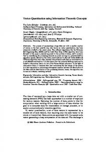
(1) The attraction between particles that are differently charged, in order to pull the particles into each other when the distinct objects move closer. (2) The repulsion between particles that have the same charge to prevent the particles aggregation.
Repulsion
Pi Attraction
COLLISION DETECTION Object A
One of the most interesting problems in computer animation is the widely researched collision detection. There are many techniques developed to increase the detecting efficiency and, at the same time, shorten the computing time such as Spheres (Hubbard, 1996; Palmer and Grimsdale, 1995; Quinlan, 1994), Axis Aligned Bounding Boxes (AABBs) (Cohen et al., 1995; Held et al., 1995), Oriented Bounding Boxes (OBBs) (Gottschalk et al., 1996), K Dops (Klosowski et al., 1998; Zachmann, 1998), Quantized Orientation Slabs with Primary Orientations (QuOSPOs) (He, 1999) and Spherical shells (Krishnan et al., 1998). These techniques seem to be effective for solid and non-deformable objects. However, the usage of these techniques with deformable objects has some drawbacks due to their restructuring process which is not efficient in real-time. The entire recalculation for bounding representation is required to be processed every time surface deformation occurs. It is not the case for a method based on particle determination (Zachmann, 1998; Parent, 2001) using interactive forces between particles. This method offers significant benefit since the interaction forces between particles can be calculated every time objects deformation occurs without any recalculation of shape bounding structure. The particle-based collision detection algorithm (Senin et al., 2003) uses the interactions forces between particles that spread over the objects surface as the main principle as shown in Fig.1. Particles are randomly spread over the surface and charged with same-charged ions, for particles on the same objects, and different-charged ions, for the particles in distinct objects. There are 2 types of forces acting on each particle which can be calculated as follows:
Object B
Fig.1 Particle-based collision detection
The position of each particle can be estimated from the summation of attractive and repulsive forces. The collision can be detected by measuring the distance between particles. When the particles come closer enough, there is high probability of collision leading to the investigation of the collision between those corresponding areas. However, the particle dispersion might not be efficient when there are more than 2 objects in the system. This is because when the other object is coming close, it can attract all particles agglomerated at one side. If there is another object crashing on another side, it may not have enough attractive forces to pull the particles back, so collision detection fails. Moreover, this method might have less efficiency when the objects have extreme expansion. As the number of particles is initially fixed, it may not be sufficient enough to cope with the broadened surface area. Besides, the random placement of particles can lead to improper particle dispersion and thus decreases the collision detection efficiency. For example, as shown in Fig.2, three particles are randomly dispersed at the right hand side of object B and so that collision cannot be detected when object A crashes on the other side.
ALGORITHM An adaptive collision detection algorithm is described in this section. First, in order to eliminate the inappropriate dispersion problem, an object surface is
Saenghaengtham et al. / J Zhejiang Univ SCIENCE A 2006 7(7):1225-1232
Particles insufficiency
Object A
Object B
Fig.2 Undetected collision caused by improper particle dispersion at the initialization
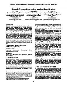
divided into several small areas with each area filled with a particle moving only within its corresponding boundary as shown in Fig.3. This can assure that the particles always cover the entire surface. Therefore, this can avoid the insufficient particles case when more than one object crashes on another object at the same time. After that, attractive forces received from particle on different objects are applied. Consequently, when objects come closer, the particles at the corresponding surface will also move into each other. The distance between this pair of particles will be observed and determined. If it is shorter than some tolerable distance, the collision is then examined precisely between these two corresponding areas. Boundary line
Pi Attraction
Object A
Object B
Fig.3 Interaction force on particle Pi based on proposed algorithm
Partitioning process To partition surface area into several groups, we have to know the number of partitions which is equal to the number of particles needed. Hence, the number of particles needed for each object is first estimated, followed by the surface partitioning. (1) The number of particles A proper number of particles for each object can be calculated as the maximum number of objects that
1227
can collide with the object. This can ensure that there are enough particles to detect the collision of several objects at the same time. In this algorithm, we apply the kissing number (Conway and Slone, 1993a; 1993b) to estimate the maximum number of objects that can attach to an object at the same time. Kissing number is the number of equivalent spheres which can touch an equivalent sphere without any intersections. The kissing number in three dimensions has been proved to be 12, as shown in Fig.4.
Attached sphere
Center sphere
Fig.4 Twelve equivalent spheres which can touch an equivalent sphere without any intersections
Therefore, 12 can be used as the number of particles when there are all the equivalent spheres in the scene. If there are less than 12 objects, the number of objects can be used instead. However, this number of particles might not be sufficient when there are several sizes of spheres. The number of particles needed for an object can be estimated as follows. The maximum number of the smallest sphere in the scene that can touch the object can be computed as follows: let X be the considered object and Y be the smallest sphere in the scene. Deposit the whole arrangement into an imaginary sphere, as shown in Fig.5. Imagine a lamp at the centre of the object X that casts shadows of surrounding spheres onto the inside surface of the imaginary sphere. Each circular shadow has an area of B and cannot overlap. Imaginary sphere (Surface area=A)
X
Circular shadow (Area=B) Y
Fig.5 Circular shadow on the imaginary sphere covering a spherical object X and the smallest spherical object Y
1228
Saenghaengtham et al. / J Zhejiang Univ SCIENCE A 2006 7(7):1225-1232
Then the number of particles needed for X is not more than A/B when A is the surface area of the imaginary sphere. We can also apply this technique to an object that has other shapes apart from sphere by completing a modification. First, each object is approximated as a collection of spheres by analyzing model geometry as shown in Fig.6. To locate a collection of spheres, all vertices have to be checked for critical points whose normal vector changes much. The suitable number of particles can then be achieved for each part of the object.
Cubic shape
V shape
Fig.6 Approximated spheres for objects
(2) Surface partitioning In order to partition object surface into a number of areas which can be calculated from the previous subsection “The number of particles”, the object vertices must be grouped. Each group is filled with a particle that can only move between the vertices in the same group. In this algorithm, LBG quantization (Linde et al., 1980) is applied to partition surface area. LBG quantization is a grouping technique which classifies vector data into several groups. The value of each group can be represented by its average value called code vector as shown in Fig.7. As the input data can y10 y11 y8 y3 y6
Codewords Voronoi region
be unlimited dimension vector, this technique can therefore efficiently partition object surface by considering several factors such as vertex position, normal vector, and color, etc. Each determinant is arranged into each vector dimension which, in this algorithm, has 2 factors to consider as will be described in the following paragraph. Since some closed adjacent vertices should not be included in the same area due to their different planes, the input vectors for partitioning should not be dependent only on their positions, but should be dependent also on their normal vectors. Therefore, each input vector for the surface partitioning process is received as a 6-dimensional vector composed of vertex coordinate and its normal vector. The average value is then computed which can divide the data into 2 groups. Each part can be divided continuously until the required number of groups is met. The algorithm for partitioning vertices is shown below: 1. Each vertex is converted into a 6-dimensional vector form Input vector: Xm=(x1, x2, x3, x4, x5, x6), where x1, x2, x3 represent vertex position and x4, x5, x6 represent its normal vectors. The set of all source vectors M is: Training sequence: (τ)=(X1, X2, …, XM). 2. The precision ε of the optimization process is set; ε>0 has a small value. 3. Dimension of data is specified, k=6. 4. The first initial code vector is estimated, by setting the number of required code vectors N=1. The average value of all source vectors can then be calculated as follows:
y12
y9
C1* =
y4 y7 y1 y2
Vectors y13
M
∑X m =1
m
.
(1)
After that, the squared error distortion value at point C1* is computed:
y5
Fig.7 Vector quantization
1 M
* Dave =
1 kM
M
∑ || X m =1
m
− C1* ||2 .
(2)
Saenghaengtham et al. / J Zhejiang Univ SCIENCE A 2006 7(7):1225-1232
5. Each reference code vector, Ci* , is used as a divider and 2 other code vectors for each part can be found. The procedure is repeated for all code vectors used as dividers. For i=1, 2, ..., N Ci(0) = (1 + ε )Ci* , (3) C N(0)+ i = (1 − ε )Ci* .
(4)
6. The N value is then doubled, N=2N. 7. Iteration process 7.1. Source vectors are classified into groups using the Euclidian distance between each input vector and its corresponding code vector. Let iteration index i=0 For m=1, 2, ..., M find the lowest value of d (C n(i ) , X m ) =
k
∑ (C j =1
nj
− X mj )2
(5)
For n=1, 2, ..., N If C n(*i ) is a code vector that creates the lowest value, then put it into the group. Q( X m ) = C n(*i ) (6)
7.2. New code vectors are calculated from the average in each group when the grouping is finished. For all value n=1, 2, ..., N C n(i +1) = ∑ X m (7) ∑ 1. Q (Vm ) = C n( i )
Q (Vm ) = C n( i )
7.3. Set i=i+1 7.4. Calculate (i ) Dave =
1 M || X m − Q ( X m ) ||2 . ∑ Mk m =1
(8)
7.5. Stable state is checked by considering the following condition: ( i −1) (i ) Dave − Dave (9) ≤ ε. ( i −1) Dave The difference between C n( i ) and C n( i −1) are still too much if the condition is not as in Eq.(9). Thus this iteration process must be repeated until it is stable. 8. When the code vectors are already stable, they are set as reference code vectors (Ci* ). * ave
Let D
=D , i ave
1229
For n=1, 2, ..., N Set C n* = C n( i ) . 9. We repeat Step 4 to Step 8 until the required number of the code vectors is reached. 10. Input vector (Xm) is then classified into each group as in Step 7.1. All N groups of 6-dimensional vectors are then achieved. Each 6-dimensional vector is converted into a vertex element by extracting the first 3 elements of the vector. Lastly, N groups of vertices, N areas, can be achieved. 11. A particle is assigned to each area. Collision detection process The procedure of this process is divided into 3 parts. First part is state the calculation of interaction forces between particles. Then, the movement of particles is discussed in the second part. Finally, the collision checking can be processed by considering the collision distance. (1) Interaction forces The interaction forces applied to each particle are calculated by summarizing the attractive force received from other particles on the neighboring objects. This attractive force corresponds to the distance between particles which can be computed as follows:
f(pi,pj)=0 when r≥Reff, f(pi,pj)=1/r2 when r