convolution in the time domain is very complicated, especially for the large lengths of ... is transformed into trivial
Journal of ELECTRICAL ENGINEERING, VOL. 53, NO. 9-10, 2002, 285–288
COMMUNICATIONS
USING OF DISCRETE ORTHOGONAL TRANSFORMS FOR CONVOLUTION ∗
∗
Anna Uˇ s´ akov´ a — Jana Kotuliakov´ a — Michal Zajac
∗∗
The convolution is a mathematical way of combining two functions to form a third one. It is the single most important technique in digital signal processing because it relates two signals of interest: input signal, output signal and the impulse response of the transmitting system. The convolution is not used only to compute the output of the system, when the impulse response is known, but also in the image signal processing, eg, for the interpolation of 2-D signals, in speech processing, eg, homomorphic modelling of the speech, noise reduction in the speech, but also in image processing, etc. The evaluation of the convolution in the time domain is very complicated, especially for the large lengths of the input signal or impulse response. So we try to find another way how to compute convolution. Complicated computation of the convolution in the time domain is transformed into trivial multiplication in the domain of some orthogonal transforms (eg, Fourier transform), for another OT’s domain this evaluation is more complicated. In this paper we present a convolution formula for some selected discrete orthogonal transforms (DOT). K e y w o r d s: convolution, orthogonal transform, discrete cosine transform, discrete Hartley transform, discrete sine transform, discrete Fourier transform
1 INTRODUCTION
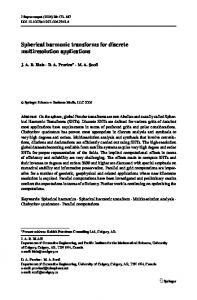
Convolution is a formal mathematical operation, just as multiplication, addition, and integration. Convolution is used in the mathematics of many fields, such as probability and statistics. In linear systems, convolution is used to describe the relationship between three signals of interest: input signal, impulse response and output signal, see Fig. 1. Mathematically, we can express convolution using the following equation y(n) = x(n) ∗ h(n) =
Dy −1
X
m=0
x(m) · h(n − m)
(1)
where x(n) is Dx length input signal, h(n) is Dh length
x(n)
Linear system h(n)
y(n) = y(n)* h(n)
of the convolution in the time domain is often replaced by computing of a more simple operation in the domain of a discrete orthogonal transform. 2 DISCRETE GONIOMETRIC TRANSFORMS
2.1 Discrete Fourier transform (DFT) Nowadays, the most preferred domain is the domain derived by Fourier transform. Convolution of two sequences is transformed by discrete Fourier transform into simple multiplication of the DFTs of these two sequences. In other words, a customary way of performing convolution numerically is to take the discrete Fourier transform of each of the two given sequences and then to do complex multiplication, element by element, in the Fourier domain. Discrete Fourier transform is defined by [1] [2] [7] [10] as N −1 1 X X(k) = X(n) · W nk (2) N n=0 and inverse discrete Fourier transform is defined as:
Fig. 1. Model of linear system using convolution
impulse response, y(n) is Dy length output signal. The length of the output signal Dy is equal to the length of the input signal plus the length of the impulse response minus one. Convolution is a mathematical operation used in signal processing, homomorphic signal processing and image signal processing (eg, in image interpolation). Computing
x(n) =
N −1 X k=0
X(k) · W −nk
(3)
where ¡ k = ¢0, 1, . . . , N − 1 , n = 0, 1, . . . , N − 1 , W = exp −j · 2π is the system of the complex base functions √ N ( j = −1 ). For the discrete Fourier transform there applies the following convolution theorem [7]: If y(n) = x(n) ∗ h(n) ,
∗
∗∗ Department of Telecommunications Department of Mathematics, Faculty of Electrical Engineering and Information Technology, Slovak University of Technology in Bratislava, Ilkoviˇ cova 3, 812 19 Bratislava, Slovakia,
[email protected],
[email protected],
[email protected], c 2002 FEI STU ISSN 1335-3632 °
286
A. Uˇs´ akov´ a — J. Kotuliakov´ a — M. Zajac: USING OF DISCRETE ORTHOGONAL TRANSFORMS FOR CONVOLUTION
x(n) and h(n) are periodic sequences with period N , and DFT
DFT
holds x(n) −−−→ X(k), h(n) −−−→ H(k), then y(n) = IDFT{X(k) · Y (k)} .
(4) YHa (k) =
Realize that DFT algorithm is based on periodic signals and on the output there is information about one period of the spectrum. By analogy, the output of the IDFT is one period of the generated periodic signal. So, if we want to compute non-periodic convolution using DFT and IDFT, we have to choose the length of the convolution N that equals at least to the length of linear convolution. It means that before DFT we extend the input sequences with zeros to achieve the needed length. 2.2 Discrete Hartley transform (DHT) Discrete Hartley transform is defined by [10] [3] XHa (k) = N −1
N −1 X
x(n) cas(2πkn/N ) .
(5)
0
N −1 X
XHa (k) cas(2πkn/N )
1h XHa (k)HHa (k) + XHa (−k)HHa (k) 2
i + XHa (k)HHa (−k) − XHa (−k)HHa (−k) .
(6)
k=0
where cas(α) = cos(α) + sin(α). The convolution theorem obeyed by the DHT is as follows [3]. If y(n) is the convolution of x(n) with h(n) , ie,
The use of the Hartley transform for convolution will require only two real multiplications per element (DFT require four real multiplications per element to do complex multiplications per element). However, it often happens, especially in image processing but also in digital filtering in general, that one of the convoluting functions, say, h(n) , is even. In that 0 case HHa (ie, the odd part of the DHT’s of the h(n) ) is zero, and the convolution theorem therefore simplifies to YHa (k) = XHa (k) · HHa (k) . In view of this simplified form of the theorem, one needs only to take the DHTs of the two data sequences, multiply together term by term the resulting two real sequences, and take one more DHT.
We differentiate four types of bases of discrete cosine transform (DCT), so we know DCT-I, DCT-II, DCT-III and DCT-IV [8], [9], [10]. The definitions of their bases are as follow: DCT-I UC–I (n, k) =
y(n) = x(n) ∗ h(n) =
DX x −1 m=0
x(m) · h(n − m) ,
(7)
UC–II (n, k) = (8)
where YHa (k) , XHa (k) and HHa (k) are the DHTs of y(n) , x(n) and h(n), respectively, and HHa (k) = e o HHa (k) + HHa (k) , the sum of its even and odd parts. The even and odd parts of the Hartley transform are given by (9) and (10) e = HHa
o HHa =
HHa (k) + HHa (−k) 1 = 2 N HHa (k) − HHa (−k) 1 = 2 N
N −1 X n=0
h(n) cos
2πkn , (9) N
N −1 X
2πkn h(n) sin . (10) N n=0
To interpret HHa (−k), or any other h( ) or H( ) where the argument falls outside the range 0 to N − 1 , add or subtract multiples of N as needed. Thus HHa (−1) is interpreted as HHa (N − 1). According to the reversal theorem, h(−n) transforms into HHa (−k).
√
n knπ o 2 · ck · cn · cos N
(12)
where n, k = 0, 1, . . . , N DCT-II
then e o YHa (k) = XHa (k)HHa (k) + XHa (−k)HHa (k)
(11)
2.3 Discrete cosine and sine transform
Inverse discrete Hartley transform is given by x(n) =
Substituting equations (9) and (10) for even and odd part of the Hartley transform into (8), DHT of the convolution can be expressed as:
√ n (2n + 1)kπ o 2 · ck · cos 2N
(13)
√ n (2k + 1)nπ o 2 · cn · cos 2N
(14)
√ n (2k + 1)(2n + 1)π o 2 · cos 4N
(15)
DCT-III UC–III (n, k) = DCT-IV UC–IV (n, k) =
where for (13)–(15) n, k = 0, 1, . . . , N − 1 . Similarly, there are four types of discrete sine transform (DST) — DST-I, DST-II, DST-III and DST-IV. They have their bases defined by following equations: DST-I US–I (n, k) =
√ n knπ o 2 · sin N
(16)
287
Journal of ELECTRICAL ENGINEERING VOL. 53, NO. 9-10, 2002
n, k = 1, 2, . . . , N − 1 DST-II US–II (n, k) =
√ n (2n − 1)kπ o 2 · ck · sin 2N
(17)
x(n) = W2m Xn (k) ,
√ 2 · cn · sin n
(2k − 1)nπ o 2N
(18)
n, k = 1, 2, . . . , N − 1 DST-IV US–IV (n, k) =
√ n (2k + 1)(2n + 1)π o 2 · sin 4N
(19)
n, k = 0, 1, . . . , N − 1 For all discrete cosine and sine transforms parameter cp is given by: ( 1 √ for p = 0 or N , 2 (20) cp = 1 otherwise. The convolution theorem for each of the discrete sine and cosine transforms is shown in Table 1 ( X 0 T (k) is the T’s of x(n) multiplied by 1/cn ). 3 DISCRETE TRANSFORMS WITH RECTANGULAR FUNCTIONS
mi 2 i ,
n=
i=0
∞ X
n i 2i
i=0
are binary expansions of non-negative integers m, n then their dyadic sum is m⊕n=
∞ X i=0
1 Nm
|mi − ni |2i .
NX m −1 d=0
where n = 0, 1, . . . , Nm − 1.
(23)
(WHT)h
y(n) = x(n) ∗ h(n) −−−−−→ Yh (k) = Xh (k)Hh (k) (25) n, k = 0, 1, . . . , 2m − 1 , ie, Yh is coordinate wise multiplication of Xh and Hh . The theorem holds also for any other order of Walsh functions (ie Walsh, Paley and Cal-Sal ordering) since the corresponding transform of x ∈ RNm ×1 can be obtain from its Hadamard transform Xh by a fixed permutation of components of Xh . The theorem for the cyclic convolution using (WHT)h is derived from the cyclic shift theorem, which says that if Xh (k) is (WHT)h ’s of sequence x(n) , and xl (n) is obtained by cyclic shift by l step, then (26)
where A(m) is called similarity transformation and equals to 1 W2m M (m)W2m 2m 0 0 ... 0 1 0 ... 0 0 1 ... 0 M (m) = . . .. .. ... ... A(m) =
0
0
...
1
1 0 0. .. .
(27)
0
Then for cyclic convolution defined by (1) applies (21)
Denote by Rm×n the space of all m × n matrices with real entries. Let Nm = 2m , m = 0, 1, 2 . . . . Then a (column) vector y = x ∗ h ∈ RNm ×1 is called dyadic convolution of x, h ∈ RNm ×1 if its n-th entry is y(n) =
is
where W2m is the 2m × 2m Walsh-Hadamard transform matrix. The theorem for dyadic convolution using Hadamardordered Walsh-Hadamard transform (WHT)h is: Let m be a non-negative integer, Nm = 2m and x, y ∈ RNm ×1 . Then holds
(WHT)h
It is well known that for some orthogonal transforms the image of the convolution of a pair of functions is equal to the product of their transforms. In order to obtain an analogous rule for Walsh-Hadamard transform the convolution should be replaced by the dyadic convolution. Recall that if ∞ X
−1
(24)
xl (n) −−−−−→ A(m)l Xh (k) ,
3.1 Walsh-Hadamard transform (WHT)
m=
m
and inverse Walsh-Hadamard transform is defined as
n, k = 1, 2, . . . , N − 1 DST-III US–III (n, k) =
The Walsh-Hadamard transform of x ∈ R2 given by [1]: 1 Xh (k) = m W2m x(n) 2
x(d)h(n ⊕ d) .
(22)
y(Nm /2 − 1 − j) = yj (Nm /2 − 1) , y(Nm − 1 − j) = yj (Nm − 1) ,
for j = 0, 1, . . . , Nm /2 − 1 © ª and yj (n) = (IWHT)h Xh (k)Hjh (k) ,
where Xh (k) = (WHT)h x(n) ,
Hjh (k) = A(m)j · Hh (k) ,
Hh (k) = (WHT)h {h(n)} , n, k = 0, 1, . . . , Nm − 1 .
(28)
288
A. Uˇs´ akov´ a — J. Kotuliakov´ a — M. Zajac: USING OF DISCRETE ORTHOGONAL TRANSFORMS FOR CONVOLUTION Table 1. Relation between convolution and DOT
Type of DOT DFT DHT DCT-I DCT-II DCT-III DCT-IV DST-I DST-II DST-III DST-IV WHT
Convolution y(n) = x(n) ∗ h(n) y(n) = x(n) ∗ h(n) y(n)/cn = [x(n) ∗ h(n)]/cn y(n) = x(n) ∗ h(n) y(n)/cn = [x(n) ∗ h(n)]/cn y(n) = x(n) ∗ h(n) y(n) = x(n) ∗ h(n) y(n) = x(n) ∗ h(n) y(n) = x(n) ∗ h(n) y(n) = x(n) ∗ h(n) y(n) = dyadic x(n) ∗ h(n)
DOT’s of the convolution YF (k) = XF (k) · HF (k) e o YHa (k) = XHa (k)HHa (k) + XHa (−k)HHa (k) 0 0 YC-I (k) = 1/ck · XC-I (k) · HC-I (k) − ck · XS-I (k) · HS-I (k) 0 YC-II (k) = 1/ck · XC-II (k) · HC-I (k) − XS-II (k) · HS-I (k) 0 0 0 0 YC-III (k) = XC-III (k) · HC-III (k) − XS-III (k) · HS-III (k) 0 0 YC-IV (k) = XC-IV (k) · HC-III (k) − XS-IV (k) · HS-III (k) 0 0 YS-I (k) = 1/ck · {XS-I (k) · HC-I (k) + XC-I (k) · HS-I (k)} 0 YS-II (k) = 1/ck · XS-II (k) · HC-I (k) + XC-II (k) · HS-I (k) 0 0 0 0 YS-III (k) = XS-III (k) · HC-III (k) + XC-III (k) · HS-III (k) 0 0 YS-IV (k) = XS-IV (k) · HC-III (k) + XC-IV (k) · HS-III (k) Y h = X h · Hh
4 CONCLUSION
As we can see from the equations mentioned in the text above and also from Table 1, only for the discrete Fourier DFT
transform holds relation x(n) ∗ h(n) −−−→ X(k) · H(k) , ie, the simple multiplication element by element in the DFTs domain corresponds to the convolution in the time domain. This also holds for discrete Hartley transform, when certain conditions are fulfilled. Discrete Fourier transform requires complex multiplications, which imposes memory and time requirements during the computation. On the other side, discrete Hartley transform requires only real multiplications, but this simple relation for the convolution is not true every time. The evaluation of the WHTs product needs only real multiplications by +1 or 1 (ie, additions or subtractions, so it is very simple to evaluate). Enumeration of the convolution in the time domain also corresponds to multiplication in WHT domain, but there we need rearranging of one of the input sequences (rearranging corresponds to multiplication input sequence by matrix A in the WHT domain). The problem of using WHT is rearranging itself because by increasing the length of convolution the number of rearrangements grows. Acknowledgements This research was supported by the Grant Agency of the Ministry of Education of the Slovak Republic (VEGA) under No. 1/7625/20 and No. 1/7627/20. Methods and algorithms for digital signal processing, development of protocols, modelling of communication channels and simulation of signal transmission via various communication media.
References [1] AHMED, N.—RAO, K. R. : Orthogonal Transforms for Digital Signal Processing, Springer-Verlag, Berlin, Heidelberg, New York, 1975. [2] BESSLICH, P., W.—TIAN LU : Diskrete Orthogonaltransformationen — Algorithmen und Flussgraphen f¨ ur Signalverarbeitung, Springer, Heidelberg, 1990.
[3] BRACEWELL, R. N. : Discrete Hartley transform, JOSA Letters, Vol. 73, No. 12, December 1983. [4] BRACEWELL, R. N. : The Fast Hartley Transform, Proceedings of The IEEE, Vol. 72, No. 8, August 1984. [5] ELLIOT, D. F.—RAO, K. R. : Fast Transforms, Algorithms, Analyses, Applications, Academic Press, Orlando, London, 1982. [6] HENNING, F. H. : Transmission of Information by Orthogonal Functions, Springer Verlag, New York, 1972. ´ J.—ROZINAJ, G. Digital Signal Processing [7] KOTULIAKOVA, ˇ (C´ıslicov´ e spracovanie sign´ alov I.) : FABER, Bratislava. (in Slovak) [8] POULARIKAS, A. D. : The Handbook of Formulas and Tables for Signal Processing, Boca Raton: CRC Press LLC, 1999. [9] RAO, K. R.—YIP, P. : Discrete Cosine Transform — Algorithms, Advantages, Applications, Academic Press, Inc., London, 1990. ´ J.—POD[10] ROZINAJ, G.—POLEC, J.—KOTULIAKOVA, ´ P.—MARCEK, ˇ ´ S. et al : HRADSKY, A.—MARCHEVSKY, ˇ ıslicov´ Digital Signal Processing II (C´ e spracovanie sign´ alov II.), FABER, Bratislava, 1997. (in Slovak)
Received 9 July 2002 Jana Kotuliakov´ a (Doc, Ing, CSc) was born (1939) in Levoˇca, graduated from the Faculty of Electrical Engineering of the Slovak University of Technology in Bratislava in 1962. Since 1964 she has been working at the Department of Telecommunications. She received the CSc (PhD) degree in 1980. Her research interests include digital signal processing, digital filtering. Michal Zajac (Doc, RNDr, CSc) was born (1951) in Bratislava, graduated in Mathematics from Comenius University in Bratislava in 1975. In 1983 he received the CSc (PhD) degree from the Institute of Mathematics of the Czechoslovak Academy of Sciences in Prague. Since 1991 he has been working at the Department of Mathematics, Faculty of Electrical Engineering and Information Technology of the Slovak University of Technology in Bratislava His research interests include linear algebra and functional analysis, and their applications in engineering. Anna Uˇ s´ akov´ a (Ing) was born (1977) in Trnava, graduated from the Faculty of Electrical Engineering and Information Technology of the Slovak University of technology in Bratislava in January 2001. She is a postgraduate student at the Department of Telecommunications FEI STU in Bratislava. Her research interests include orthogonal transforms and digital image processing.