Using UML for Automatic Test Generation Alessandra Cavarra1 , Charles Crichton1 , Jim Davies1 , Alan Hartman2 ,Thierry Jeron3 , Laurent Mounier4 1
Oxford University Computing Laboratory Wolfson Building, Parks Road Oxford OX1 3QD, UK {crc,ale,jdavies}@comlab.ox.ac.uk 2 IBM Haifa Research Laboratory
[email protected] 3 IRISA / INRIA Rennes
[email protected] 4 VERIMAG—Centre Equation
[email protected]
Abstract. This paper presents an architecture for model-based verification and testing using a profile of the Unified Modeling Language (UML). Class, object, and state diagrams are used to define essential models: descriptions that characterise the entire range of possible behaviours, in terms of the actions and events of the model. Object and state diagrams are used to introduce test directives. Models written in this profile may be compiled into a tool language: the Intermediate Format (IF). Descriptions written in IF can be animated, verified, and used to generate tests. As well as illustrating the testing architecture adopted, the paper defines the profile for UML, explains testing directives, the basis of the compilation into IF and of the test generation process, and reports, and reports upon the problems encountered.
1
Introduction
Software systems are extremely complex; the amount of information contained in a system implementation is more than we can hope to comprehend. The same is true of the natural world that surrounds us, and we cope with it in exactly the same way: by creating a suitable model of the system, and working with that. The suitability of a model depends upon the intended application. Clearly, we must include every piece of information that is relevant to our purpose, but we must also try to exclude any piece of information that is not. A model with too much information may be difficult to comprehend, and too complex for automated software engineering. A model that is entirely suitable for one purpose may be less suitable for another: some vital piece of information may be missing. If we have several purposes in mind, then we may need several different models of the same system. In this paper, we describe a modelling architecture for the purposes of modelbased verification and testing. We explain how the resulting models can be
translated—automatically—into a language of state machines, animated, verified, and used as a basis for automatic test generation. Models and test directives are described using the Unified Modeling Language (UML) [?], although the architecture could be applied to any modeling language with a suitable, state-machine semantics. We begin with a description of the architecture itself. In Section ??, we define a UML profile for models and purposes. In Sections ??, we explain how models are compiled into the Intermediate Format (IF). In Section ?? we explain the principles behind the use of these models for the generation of test suites. We end with a discussion of related and future work.
2
Architecture
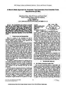
The first component of the architecture is the system model, written in UML; this is a collection of class, state, and object diagrams: the class diagram identifies the entities in the system; the state diagrams—one for each class—explain how these entities may evolve; the object diagram specifies an initial configuration. The second component, again written in UML, is the test directive; this consists of particular object and state diagrams: the object diagrams are used to express test constraints and coverage criteria; the state diagrams specify test purposes. The system model and the test directives can be constructed using any of the standard toolsets, such as Rational Rose [?] or Together Control Center [?].
System model
compile
State machine IF
UML class diagram object diagram
generate / model-check
state diagrams
Test suite / result Test directive
UML
object diagrams
state diagrams
API
Fig. 1. An architecture for automatic test generation
The compiler takes the model and produces a collection of interacting state machines, written in the Intermediate Format (IF) language [?]. The form of each machine is dictated by the state diagrams of the model, their interaction mimics the action–event mechanism of UML.
An IF representation can be animated, verified, or model-checked using the tools of the CAESAR/ALDEBARAN Development Package (CADP) [?]. In this case, the test directive describes a test upon the model, a property to be checked, and the output is either a confirmation that the property holds, or an explanation of why it does not. Alternatively, an IF representation can be provided as input to the TGV (Test Generation with Verification) tool [?]. In this case, the state diagram component of the test directive is used to guide the exploration of the underlying transition system, constructed—on-the-fly, if necessary—from the IF state machine description. TGV provides output in Tree and Tabular Combined Notation (TTCN)— a standard format in the telecommunications industry—but this output can be translated to produce test cases in the language of any API (Applications Programming Interface), whether this is C, C++, or Java (see Section ?? for details).
3
The AGEDIS Modelling Language
This work is being carried out as part of the EC-funded AGEDIS project [?]. For this reason, we will refer to the subset of UML that we have chosen as the AGEDIS Modelling Language (AML). 3.1
Choosing UML
A primary consideration in choosing this language was accessibility, or ease of use. It must be within reach of the ordinary practitioner—modeller or tester— in the software industry. This led us to a graphical notation, based upon an existing, industry-standard modelling language: UML was the best candidate. Another consideration was domain appropriateness, a combination of adequacy and abstraction. The chosen subset of UML must be rich enough to describe the properties that we wish to test. At the same time, it should not include any unnecessary constructs, complication, or complexity: it should be as simple as possible. Closely related is a consideration of compositionality, or scalability. It should be possible to combine models of components to produce a model of a complete system. The existing semantics of UML does not present enough information to achieve this; we have extended it with an explanation of message passing and interaction. 3.2
Using UML
The UML [?] is a set of techniques for specification, visualisation, and documentation. The language is based primarily upon object-oriented methodology; however, concepts were added from Harel’s language of StateCharts [?], Petri Nets, Message Sequence Charts and SDL.
An important aspect of UML is the presence of variation points in the language semantics: the definition of the language is intentionally incomplete; further interpretation is required before a model written in UML can be used as a basis for formal analysis or automatic test generation. Also required is instantiation. UML does not include a language of data types and operations; instead, these are written in the target language of the specification, normally an imperative programming language. If we wish to compile our models, we must define a target language. 3.3
Target language
We will use IF itself as our target language. Operations, actions, and data types will all be written using a basic subset of IF syntax, accessible to anyone who has some familiarity with imperative programming languages. There are two obvious advantages to this choice: our diagrams will use the same target language, whether the language of implementation is C, C++, or Java; the compiler can focus upon the translation of state machines, and the interpretation of UML actions; it does not need to translate primitives. The translation from the implementation language of an API—whether it is C, C++, or Java—to this syntax is easily automated. The only aspect that invites user intervention is the choice of data representation. The primitive types defined for IF include the standard C datatypes, integers, arrays, and records. So user intervention is not required ; however, it may be desirable. 3.4
Attributes in class diagrams
In our profile, attributes may be observable: the values of observable attributes may be inspected at any point during a test. By default, attributes are not observable: we indicate that they are by adding a tag. Operations may also be observable, in that the occurrence of the operation (and any return value) will be recorded in any projected model. Furthermore, they may be controllable, indicating that they may be called from outside the system—during a test; we may use another tag to indicate this. We use associations in place of data attributes of class type. In a class diagram, an association is represented as a solid line between classes. Associations may be annotated with roles—an attribute name at one end reveals the (formal) name used for an object of the closer class, within the context of an object of the other class. 3.5
Object diagrams
An object diagram shows the state of the system at a certain point in time, as a collection of objects, each in a particular state. We will use object diagrams to describe the initial configuration of the system model, to specify a starting configuration in a test directive and to flag configurations for inclusion or
exclusion in a test model. The object diagram notation is similar to the class notation, although there are now only two compartments to each rectangle. The state of an object may be constrained using an assertion, a state name from the corresponding state diagram, or by constraining the values of its attributes. The presence of a link between objects indicates that communication is possible: call actions in one object can produce call events in the other; send actions in one object can produce signal events in the other. A link may be decorated with information about roles: an attribute name at one end of a link reveals the name used, within the context of the closer object, for the object at the other end. We will annotate the object diagram representing the initial state of the system by the stereotype .
3.6
State diagrams
A state diagram shows how an object will react to the arrival of an event. Each reaction may be a sequence of actions, possibly accompanied by a transition from one named state to another. An event represents the receipt of a signal, or the effect of an operation call. An action represents the sending of a signal, or the call of an operation. In a diagram, each state is represented by a rectangle with rounded corners. To simplify the presentation, we may factor some of the transition information into the rectangles: actions that are common to every incoming transition may be included as entry actions for that state; actions that are common to every outgoing transition may be included as exit actions. If the only transition(s) that do not mention a particular action are self-transitions, then we may make these internal transitions, and proceed with the factorisation. Each internal transition is represented by the name of an event, followed by an action expression. An optional guard —a Boolean-valued expression—tells us whether a particular occurrence of the event should trigger the specified actions—if it is false, then the fact that the event has occurred is simply forgotten. In general, the event must actually occur for the guard to be evaluated— the value of the guard may depend upon the values of attributes in the event. A transition may be annotated with an event, a guard, and an action expression. The transition begins, or fires, with the occurrence of the trigger event. If there is a guard, it is evaluated before the action list is considered—should it prove to be false, no change in state will take place; in a sense, the transition is cancelled. If there is no guard, or if the guard is true, then the exit actions of the source state are performed, followed by the actions of the transition itself, and then, finally, the entry actions of the target state. If two outgoing transitions are enabled at the same time—either because they are both labelled with the same event, or because neither requires an event, and both guards are true—then either may fire. State diagrams cope easily with the phenomenon of nondeterminism.
3.7
Actions
A call action is an action in which a stimulus—a call event—is created that can trigger an action sequence in another object. Call actions are synchronous: the caller waits for the event to be processed before resuming execution. A send action also creates a stimulus—this time, a signal event. Send actions are asynchronous: the caller proceeds without waiting for the event to be processed. In this class diagram, we may include a tag in each name compartment to indicate whether these events are observable or controllable—can be sent by the environment. To indicate that these are classes of signal events, we label each class with the stereotype . Both send and call actions begin with the name of the target object, which must be within the scope of the state diagram. It could be one of the declared attribute names, but it is more likely to be a role name, at the far end of a link or association. In the case of an object diagram, the role name is not needed to identify the callee object unless the object has been left anonymous, or is known by a different name inside the state diagram of the current object. Role names are not needed in class diagrams unless the object performing a particular role can be created during the test phase—in this case, it can’t be named in the initial object diagram. 3.8
Test directives
We now introduce the diagrams used to express test directives. The compilation of directives into IF will be described in the next section, the inputs provided to the test generation tool by the AML–to–IF compiler, in Section ??. Test directives consist of three distinct parts: test purposes, test constraints, and coverage criteria. Test purposes are used to describe behaviours that one wants to test. In AML, a test purpose is represented as a state diagram, with a number of special states. These are used to steer the test generator during the selection of relevant execution sequences. We will label any state diagram that forms part of a test directive with the stereotype (there is no need to stereotype the state diagrams used to define the system model: these will have the corresponding class as a classifier ). Test constraints are used to describe additional restrictions on the test cases one wants to generate, again steering the test generator during the selection of relevant execution sequences. Test constraints are described by object diagrams. We propose four kinds of test constraints: – : to express that at least one state of the sequences of the specification selected for test generation must satisfy the given constraint; these constraints are specified by object diagrams stereotyped by .
– : to express that no state of the sequences of the specification selected for test generation should satisfy the given constraint; the corresponding object diagrams are stereotyped by . – : to give a global constraint on the start state of the expected test case (therefore it also defines the end of a preamble); they are described by object diagrams stereotyped by . – : to give a global constraint on the termination state of the expected test case (therefore it also defines the end of a postamble); their object diagrams are stereotyped by . Coverage criteria describe coverage requirements when generating sets of test cases. More precisely, a constraint is expressed as a set of expressions over object variables. For each reachable combination of these expression values, a test case is generated in which at least one state of the selected sequences satisfies the given constraint. Coverage criteria can be viewed as a (possibly huge) set of constraints.
4
Compilation
The Intermediate Format (IF) language was developed to sit between high-level specification languages, such as Sdl [?], Promela [?] or Lotos [?], and toolspecific internal representations. IF representations can be passed between tools, and translated into other languages: for example, Sdl specifications can be analysed using the Spin model-checker [?]. Moreover, translating high-level languages into IF may also allow to extend (or fix) some (open) parts of their semantics: for example IF is used to give a precise timed semantics to Sdl [?]. The choice of using IF as an intermediate format between the AML modelling language and the test generation tool is motivated by several arguments: – First of all, it allows us to re-use some of the tools already developed within the IF environment. In particular the existing IF simulation engine, able to generate on-the-fly the underlying labelled transition systems associated to an IF description, will be used as a front-end of the test generation tool. – Moreover, using IF offers a relative flexibility when defining the AML semantics: for a given AML construct, several translation schemes can be foreseen, independently of the simulation engine. Thus, it becomes easy to define the AML semantics in an incremental way, and to extend the compiler accordingly. – Finally, the potential loss of efficiency caused by the use of an intermediate representation (instead of performing the simulation directly at the AML level) is largely compensated by the optimization tools available at the IF level. In fact, previous experience with Sdl demonstrated that using IF and static analysis techniques gave us a much more efficient simulator than the already existing ones. In particular model-based test generation can be advantageously combined with slicing techniques[?]
In IF, each of the objects in our specification is represented as an extended finite state machine, or process instance. The state of each process—the values of local variables—is private; processes evolve and communicate by sending and receiving asynchronous signals along specified signalroute instances. Process and signalroute instances can be either created statically (at system initialisation), or dynamically (at run-time). A signalroute can be reliable or lossy, peer-to-peer or multicast, FIFO or multiset, timely or delayed. As in UML, the arrival of a signal may trigger a transition between states, accompanied by a specified sequence of actions. This sequence may involve sending signals to other processes, or changing the values of local variables. The process of compilation revolves around the state diagrams of our model; each of these will be transformed into an IF process. The initial (or start) object diagram for the model (or test) defines the initial configuration of processes. The class diagram provides information about data types and operations. The translation into IF defines an effective semantics for the UML language of state diagrams. We need to define: an IF signal for each operation; an acknowledgment signal, including a return value parameter, for each synchronous operation (since communications are always asynchronous in IF); a process for each object in the model; a communication buffer for each object. 4.1
States
Each state in a state diagram is translated into an IF control state, with stability and initiality attributes. If a state is marked as unstable, then any transaction through this state—a transition to, and a transition from—is treated as atomic, across the system. If a state is marked as initial, then it is treated as an initial state of the process. A start state in a state diagram becomes an :init state in IF; a finish state becomes a state with no transitions. To translate a simple state, we append the entry actions to every incoming transition; prepend the exit actions to every outgoing transition; transform any internal transition into an external, self transition, but without entry or exit actions. 4.2
Transitions
Having mapped the object states into IF, we can construct a transition in IF for each transition in the state diagram: from currentState input operationName from thisBuffer if guard do action ; [ output ack(returnValue) to callerBuffer ] to newState The output clause is used only in response to synchronous operations, modeled as call actions.
4.3
Events
A call event represents an operation invocation in which the caller will be notified of completion, and provided with any return value. We translate call events into IF signal inputs: input operation-name (reference-list) from buffer where operation-name is an operation of the current object; reference-list is a list of variables in which the received parameters are stored, buffer the name of the buffer from which the event will be read. To achieve synchronisation with the caller object, we add a symmetrical action after every signal input representing a call event, sending an appropriate completion or return signal to the caller. A signal event represents the reception of a UML signal—used to model asynchronous communication. We translate signal events directly into IF signal inputs: input signal (reference-list) from buffer but this time there is no matching acknowledgement action. 4.4
Guards
These are translated into post guarded inputs where the received parameters can be tested; this guard is evaluated after the input is done and, if false, the execution of the transition is disabled, restricting the values that the process is willing to accept. In our modeling language, guards will be expressed by IF expressions. 4.5
Actions
To translate a call action, we must add an additional, stable state to the IF representation of the object. This is the state in which the object has issued the call, but the operation has yet to return. If the state diagram has a transition from State1 to State2, labelled with call action a, then we obtain an IF representation of the form from State1 input event from callerBuffer if guard do action ; to StateX
from StateX input ack_a from calleeBuffer to State2
Each send action becomes an IF output: output signal(parameters) to targetBuffer This has the effect of appending the specified signal to the buffer associated with the target object.
5
Test generation
The AGEDIS test generation tool is based on the principles of two existing tools TGV [?] and GOTCHA-TCBeans [?]. These tools have different principles, summarised below; we describe how these principles are adapted and combined in the AGEDIS test generation tool. 5.1
TGV
TGV is a test generation tool developed by Verimag and Irisa [?] and based on a sound testing theory [?]. The theory and test generation algorithms ensure that no conformant implementation can be rejected by a test case and that it is theoretically possible to generate a test case that can reject any non-conformant implementation. Models of specifications are IOLTS (Input Output Labelled Transition Systems) where inputs, outputs and internal events are distinguished. The behaviour of the implementation under test is unknown (black box) but we suppose that it can be modelled by an IOLTS. A conformance relation ioco defines the correct implementations I with respect to a given specification S. To allow the detection of incorrect quiescence of I (by timers in test cases), ioco is defined in terms of traces of the suspension automata δ(I) and δ(S). δ(S) is built from S by the addition of loops labelled by a new output δ in each quiescent state, i.e. a livelock, a deadlock, or an absence of output. Now, I ioco S if after every trace of δ(S) (including δ), the outputs of I are included in those of S. The two main inputs of TGV are the IOLTS of the specification S and a test purpose T P used for test selection. T P is a complete automaton with Accept and Reject states. Accept states are used to select behaviours of S one wants to test, while Reject states may prune the exploration of S. Labels of T P are regular expressions matching S’s labels and a particular label ∗ meaning “otherwise”. The test generation process is composed of three operations. A product S × T P which synchronises on common actions is used to mark states of S with Accept and Reject states of T P . This operation may also unfold S. The second operation computes the suspension automaton δ(S × T P ) and determinises it while propagating the marking on state sets. The result is a deterministic IOLTS SPvis , with same observable traces as δ(S) and where Accept and Reject states mark behaviours accepted or rejected by T P . A selection operation then builds two possible objects: a complete test graph CT G consisting of all traces leading to accept (to which a Pass verdict is associated), plus divergences on these traces by outputs of S (giving rise to an Inconclusive verdict); alternatively a test case T C (a subgraph of CT G) is obtained by the additional constraint that test cases never have controlability conflicts, i.e. choices between an output and another action. In both cases, in any state of CT G or T C where an output of S is observable, Fail verdicts are implicit on all unspecified outputs. Finally a mirror image of CT G and T C is applied which inverts inputs and outputs. To our knowledge, TGV is the only test generation tool that can generate test cases with loops, while others are restricted to sequences or trees. TGV also accepts optional files which define the test architecture. A rename file is used
to rename labels of S, a hide file specifies unobservable actions of S, and an IO file distinguishes inputs from outputs among observable actions. All three files support regular expressions. Some additional options may be used to tune the test generation process: exploration depth, computation of postambles, priorities on the order of exploration of transitions, synthesis of timer operations (start, cancel, timeout). In order to avoid state explosion, the specification S can be given implicitly by a simulation API (functions for S’s traversal). In this case, the test generation operations are not applied in sequence but on-the-fly (except for some cases of conflict resolution). and only the necessary parts of S, of S × T P and of P Svis are built. Consequently, TGV can be used for different specification languages, as soon as a simulation API can be produced by a compiler of this language. This has been done for SDL with ObjectGeode (Telelogic), Lotos with the CAESAR compiler (Inria Grenoble), UML with the Umlaut tool and IF with the IF2C compiler. TGV also accepts specifications in the form of explicit graphs in the BCG and Aldebaran formats. Test cases are produced in BCG or Aldebaran format, and in pseudo-TTCN for SDL specifications. 5.2
GOTCHA
GOTCHA is a test generation tool developed by the IBM Research Laboratory in Haifa. It is an extension of the Murφ model checker. The main differences with TGV are the following: The specification model describes the observable behaviour of the system, not its internal behaviour. The model is a finite state machine with edges labelled with inputs and states labelled with both a control state and the values of observable variables. The test generation process is based on a traversal of the finite state machine directed by coverage criteria and test constraints. Coverage criteria are based on an abstract state space defined by expressions on subsets of variables and control states. This abstract state graph is conceptual and not built explicitly. A state coverage criterion is a boolean expression on an abstract state while a transition coverage criterion is a pair of boolean expressions on the source and target states of an abstract transition. Both criteria are transformed into a finite set of coverage tasks that instantiate the conditions. The first phase of test generation determines which of the specified coverage tasks are reachable, and chooses a random representative of each reachable task. The test generation engine then covers each of these tasks by a set of paths in the specification. Test constraints may be used to restrict test sequences and limit the reachable set of states and transitions in the finite state machine. It is possible to forbid the traversal of a state which satisfies a condition or to forbid certain paths which satisfy boolean conditions on their beginning, middle, end, and length. Several traversal strategies can be used, including on-the-fly and coverage directed traversal. Test cases computed by GOTCHA are sequences composed of actions and expected values of observable variables. Non-deterministic transi-
tions in a test case are dealt with by the use of an ”inconclusive” outcome, as well as the ”pass” and ”fail” outcomes for a test case. 5.3
Principles of the AGEDIS test generation tool
In the AGEDIS project, we are developing a test generation engine which combines the principles of TGV and GOTCHA, namely test selection using test purposes, test constraints, and coverage criteria. Test cases allow a combination of observations: outputs as in TGV, but also values of variables as in GOTCHA. The input of the test generation process is an IF model, obtained by translation from an UML model. This model contains the specification of the system, test directives and the test architecture. Additionally, a mapping between UML and IF objects is generated, allowing the description of test cases in terms of UML objects. The test architecture consists of a list of controllable signals and calls and a list of observable signals, calls and variables corresponding to the IO and hide files of TGV. In the sequel, we focus on the different test directives and how they are used for test generation. Test directives Test directives are used to identify particular behaviours of the specification one wants to test. The tool uses three kinds of directives: test purposes a` la TGV, test constraints and coverage criteria `a la GOTCHA. Test purposes and test constraints can be combined as well as test constraints and coverage criteria. Notice that in the case of dynamic creation, test directives must be paired with the set of process instances considered. Test purposes are similar to the Goal observers of TestComposer (Telelogic). They are described as extended automata in a IF like syntax, with Accept and Reject states but also Preamble and Postamble markers. Transitions are labelled with asynchronous inputs/outputs, synchronous calls, guards and assignments referring to the specifications objects and/or private variables. Test constraints are composed of an operator and boolean predicates on the specification variables and control states. Several kinds of operators are used: bool expr means that at least one state of the selected sequence should satisfy the constraint; bool expr means that no state should satisfy the constraint; bool expr and bool expr define preambles and postambles in test cases. As in GOTCHA, coverage criteria are specified as boolean expressions on states and transitions of an abstract state graph defined by expressions in finite codomains on control states and variables. Each reachable combination of these expressions must be covered by at least one sequence, as described in [?]. Test generation The test generation engine will be mostly based on TGV, but it has to be extended in several ways. Since test directives refer to specification variables and control states in boolean predicates or guards, they must be compiled and linked with the IF specification of the system into a simulation API. The simulation API used by
the test generation engine consists of functions for the construction and observation of either the product between the specification and test purposes constrained by its test constraints, or the specification constrained by the coverage criteria. The product between the specification and test purpose is different from TGV. In order to avoid unnecessary intermediate states, a transition of the specification may consist of an atomic sequence of actions, possibly starting with an input, and followed by outputs and/or internal actions. As a transition of a test purpose contains only one action (observable or not), this transition matches a transition of the specification which contains this event. Hiding according to the test architecture, is also treated differently as we have to hide some actions in a transition, but not necessarily all actions. In TGV, S and S × T P are IOLTS where states are just identifiers. In AGEDIS, values of variables may be observable, so states of S and S × T P carry a vector of values of observable variables. After determinisation, as a state is a set of states, it carries a set of vectors of values which defines the set of correct observations of the observable variables. This set is attached to the corresponding state of the test case, if this one is selected. All other observations lead to a fail verdict. The test selection process incorporates TGV and GOTCHA mechanisms. For each test purpose it builds one test case (or the complete test graph), also satisfying the test constraints. In the case of a coverage criteria, it builds a set of test cases or a test graph covering all reachable coverage tasks. To avoid redundancy in the computation, all test purposes and coverage criteria can be processed together. Breadth first and depth first traversal strategies, both onthe-fly, are possible.
6
Discussion
The work described here is still in progress. An architecture has been defined, and the AML to IF compiler is being written. Moreover, some modelling with AML is currently being done by our industrial partners. 6.1
The AGEDIS project
This work is being carried out as part of the EU-funded AGEDIS project [?]; the acronym is formed from the phrase Automated Generation and Execution of test suites for DIstributed component-based Software. The project involves seven industrial and academic research centres. The work is coordinated by IBM Research, Haifa; the academic contributors are the University of Oxford, IRISA, and the Universit´e Joseph Fourier, Grenoble. The industrial partners are France Telecom, IBM Hursley (UK); Intrasoft International (Luxembourg); and imbus AG (Germany). The aim of the project is to develop methods and tools for the automation of software testing, with particular emphasis on the testing of distributed, component-based systems; the project started in November 2000, and is expected
to run until October 2003. The academic contribution is to define the modelling language, describe a suitable semantics, address the problems of complexity, and to design and implement the new test generation tool from the existing ones. 6.2
Conclusion and related work
The prospect of some degree of automation in the testing process is clearly an attractive one. Computing is becoming more pervasive, and more critical to our lives; at the same time, designs are becoming more complex, and interactions between components are becoming harder to measure and predict. Software testing is becoming more difficult, and more expensive. A considerable amount of research has been carried out into the application of Finite State Machine (FSM) notations to testing, and test generation, particularly with regard to the testing of communicating systems [?]. This research solves fundamental problems in testing, but does not attempt to address the problems of scale and complexity encountered in modern software engineering. Other research, from theories of testing for StateCharts [?] and methods for behavioural model generation [?], through to toolkits for automated testing [?], and packages for generating input sequences for testing user interfaces [?], has taken a more pragmatic, industrial approach. Of these, only one [?] presents an architecture: a precursor to that adopted for the AGEDIS project. There already exist tools for the generation of test cases from UML models. Umlaut/TGV [?] is such a tool: Umlaut provides a simulation API used by TGV for test generation This tool suffers from limitations in the considered UML subset and TGV limitations in the expression of test directives. The main advantage of the AGEDIS test generation tool is its ability to combine different test directives: coverage criteria, test purposes and test constraints. This allows the user to tune the selection of test cases with respect to the budget of the test campaign. Moreover, a hierarchy of test suites can be constructed with the property that the larger the test suite, the greater the coverage of the implementation. This hierarchy is particularly useful in regression testing. TestComposer (Telelogic) already combines coverage and test purposes for SDL but coverage is limited to branch coverage. There are several reports of success in automated test case generation. One of the examples [?] includes the comment: However, questions remained about the scalability of the approach. . . A state-machine based approach. . . would perhaps be more appropriate in such circumstances. The focus of our research is exactly this: we are working towards scalable methods for automated test generation, using object-oriented principles, and building on fundamental research from the world of finite state machines.
References 1. M. Bozga, J.Cl. Fernandez, and L. Ghirvu. Using Static Analysis to Improve Automatic Test Generation. In S. Graf and M. Schwartzbach, editors, Proceedings of TACAS’00 (Berlin, Germany), LNCS, pages 235–250. Springer, March 2000.
2. M. Bozga, S. Graf, L. Mounier, I. Ober, J.L. Roux, and D. Vincent. Timed Extensions for SDL. In Proceedings of SDL FORUM’01, LNCS, 2001. to appear. 3. Ed Brinksma and Tommaso Bolognesi. Introduction to the ISO specification language LOTOS. Computer Networks and ISDN Systems, 14(1), 1987. 4. Rational Software Corporation. Rational rose. June 2001, ”http://www.rational.com”. 5. Ibrahim Khalil Ibrahim El-Far. Automated construction of software behavior models. Master’s thesis, American University of Beirut, 1995. 6. E. Farchi, A. Hartman, and S. Pinter. Using a model-based test generator to test for standard conformance. IBM System Journal - special issue on Software Testing, 2001. To appear. Currently available at http://www.haifa.il.ibm.com/projects/verification/gtcb/publications.html. 7. M. S. Feather and B. Smith. Automatic generation of test oracles—from pilot studies to application. Automated Software Engineering, 8(1):31–61, January 2001. 8. Jean-Claude Fernandez, Claude Jard, Thierry Jeron, and Cesar Viho. An experiment in automatic generation of test suites for protocols with verification technology. Science of Computer Programming, 29(1-2):123–146, 1997. citeseer.nj.nec.com/2326.html. 9. J. Fernandez, H. Garavel, A. Kerbrat, R. Mateescu, L. Mounier, and M. Sighireanu. CADP: A protocol validation and verification toolbox, 1996. 10. B. Gregor and V. Petrenko. Protocol testing: review of methods and relevance for software testing, 1994. 11. I. Gronau, A. Hartman, A. Kirshin, K. Nagin, and S. Olvovsky. A methodology and architecture for automated software testing. http://www.haifa.il.ibm.com/projects/verification/ gtcb/papers/gtcbmanda.pdf, 2000. 12. Object Management Group. Unified Modeling Language (UML) 1.4 draft, February 2001. http://www.omg.org/cgi-bin/doc?ad/2001-02-13. 13. David Harel and Eran Gery. Executable object modeling with statecharts. In Proceedings of the 18th International Conference on Software Engineering, pages 246–257. IEEE Computer Society Press, 1996. citeseer.nj.nec.com/article/harel97executable.html. 14. Gerard J. Holzmann. The model checker SPIN. IEEE Transactions on Software Engineering, 23(5):279–295, May 1997. 15. ITU-T. Recommendation Z.100. Specification and Description Language (SDL). Technical Report Z-100, International Telecommunication Union – Standardization Sector, Gen`eve, November 1999. 16. T. J´eron, J.-M. J´ez´equel, and A. Le Guennec. Validation and test generation for object-oriented distributed software. In IEEE Proc. Parallel and Distributed Software Engineering, PDSE’98, Kyoto, Japan, April 1998. 17. T. J´eron and P. Morel. Test generation derived from model-checking. In Nicolas Halbwachs and Doron Peled, editors, CAV’99, Trento, Italy, volume 1633 of LNCS, pages 108–122. Springer-Verlag, July 1999. 18. The AGEDIS project, 2000. ”http://www.agedis.de”. 19. S. Rosaria and Microsoft Corporation H. Robinson, Intelligent Search Test Group. Applying models in your testing process. Information and Software Technology, 42:815–824, 2000. 20. TogetherSoft. Together control centre. June 2001, ”http://www.togethersoft.com”. 21. J. Tretmans. Test generation with inputs, outputs and repetitive quiescence. Software—Concepts and Tools, 17(3):103–120, 1996.