Paper #1446
1
VHDL-AMS and Verilog-AMS as Alternative Hardware Description Languages for Efficient Modeling of Multi-Discipline Systems F. Pêcheux, C. Lallement, Member, IEEE, and A. Vachoux, Member, IEEE
Abstract—This paper focuses on commonalities and differences between the two mixed-signal hardware description languages VHDL-AMS and Verilog-AMS in the case of modeling heterogeneous or multi-discipline systems. The paper has two objectives. The first one consists of modeling the structure and the behavior of an airbag system using both the VHDL-AMS and the Verilog-AMS languages. Such a system encompasses several time abstractions (i.e. discrete-time and continuous-time), several disciplines, or energy domains (i.e., electrical, thermal, optical, mechanical, and chemical), and several continuous-time description formalisms (i.e., conservative-law and signal-flow descriptions). The second objective is to discuss the results of the proposed modeling process in terms of the descriptive capabilities of the VHDL-AMS and Verilog-AMS languages and of the generated simulation results. The tools used are AdvanceMS from Mentor Graphics for VHDL-AMS and AMS Simulator from Cadence Design Systems for Verilog-AMS. The paper shows that both languages offer effective means to describe and simulate multi-discipline systems, although using different descriptive approaches. It also highlights current tool limitations since full language definitions are not yet supported. Index Terms— VHDL-AMS, Verilog-AMS, Mixed-signal Simulation, Accelerometer, EKV MOS Model, Generalized Kirchhoff Laws, Optical link, Chemical system, Airbag, Thermoelectrical Interactions
F
I. INTRODUCTION
or the past three decades, hardware description languages (HDLs) have been widely used to model and simulate systems belonging to various engineering fields, from digital and analog electronics to mechanics and chemistry. For a long time, all these fields have been completely separated, each scientific community having its own design methodologies, tools and idiosyncrasies. Dedicated HDLs supporting the Manuscript received June 6, 2002. F. Pêcheux is with the LIP6 Integrated Systems Architecture Department, Université Pierre et Marie Curie, 12, rue Cuvier, 75252 Paris Cedex 05, France (phone: 00-33-1-4427-6528; fax: 00-33-1-4427-7280; e-mail:
[email protected]). C. Lallement, is with the ERM-PHASE/ENSPS Laboratory, Pôle API, Bld S. Brant, BP. 10413, F-67412 Illkirch Cedex, France (e-mail:
[email protected]). A. Vachoux is with the LSM Microelectronic Systems Laboratory, Ecole Polytechnique Fédérale de Lausanne, CH-1015 Lausanne, Switzerland (email:
[email protected]).
description and the simulation of the logical structure of a system belonging to a particular engineering domain were, and are still available. They allow the description of a system as a possibly hierarchical connection of predefined submodels, or primitives. For example, in the electrical/electronic domain, the SPICE simulator and all its derivatives allow the description of the netlist of a circuit using electrical primitives such as resistors, capacitors, sources and transistors. In an attempt to support the modeling and simulation of nonelectrical systems as well, several modeling methods using energy equivalences between the electrical domain and other domains such as mechanical, thermal or fluidic domains have been proposed [1][2][3]. With the advent of nano-technologies, the design of innovative integrated devices, like Micro-Opto-ElectroMechanical Systems (MOEMS), has shifted from vertical only to both vertical and horizontal integration. Using the benefit of all the experience acquired in incremental design, MOEMS design now involves strong “horizontal” interaction of different application-field parts on the very same chip (e.g., mechanical, electrical, thermal, fluidic parts), with partial close coupling between these fields. Neglecting the interaction effects or the cross coupling between parts may have disastrous consequences on the final design in terms of a loss in performance or an increase in design time. One way of addressing this issue is to use a consistent modeling and simulation framework that allows for the description of systems from different disciplines and for the description of interactions between these systems. This is where the VHDL-AMS HDL [4][5][6] and the Verilog-AMS HDL [7][8] come in as effective backbones of the aforementioned framework. In this paper, we therefore propose to compare the modeling power of these two HDLs. In order to illustrate this, we present a meaningful case study that consists in modeling the structure and the behavior of an airbag system using both the VHDLAMS and the Verilog-AMS languages. Such a system is well suited for our purpose as it encompasses several time abstractions (i.e. discrete-time and continuous-time), several disciplines, or energy domains (i.e., electrical, thermal, optical, mechanical, and chemical), and several continuoustime description formalisms (i.e., conservative-law and signalflow descriptions). In addition, the case study allows us to highlight the key modeling capabilities offered by both analog
Paper #1446
2
and mixed-signal HDLs in terms of expressive power and quality of simulation results. The paper does not intend to provide a complete presentation of the two languages. Rather, it focuses on specific analog and mixed-signal modeling and simulation aspects and on how the two design languages can actually address them. The paper is organized as follows. Section 2 introduces the context of the work, i.e. the modeling and simulation aspects that are addressed in the paper. It gives a short presentation of the VHDL-AMS and Verilog-AMS design languages. Section 3 presents a complete multi-discipline case study, consisting of an airbag system, and discusses selected VHDLAMS and Verilog-AMS models. Section 4 gives relevant simulation results obtained with the VHDL-AMS and the Verilog-AMS tools. Section 5 summarizes the insights we can learn from the case study. Finally, section 6 gives some conclusions. II. CONTEXT OF THE WORK A. Modeling and Simulation aspects Modeling is at the core of any design process. This task essentially consists in developing abstract descriptions of some physical reality in such a way that they are useful for the design process. Models may be used to validate characteristics of some part or of the whole of the designed system, e.g. its functionality or its performances. Such models are simulation models, or executable models that produce a response when acted upon by stimuli. These are the kind of models this paper is dealing with. To be complete, models may also be used as a support for a synthesis process, i.e., the progressive refinement process that starts from an abstract description of what the system should do and in which conditions, i.e. its specifications, and that ends when a detailed description of a realization that meets the specifications is obtained. Models may describe the behavior and/or the structure of the designed system at various levels of details, or levels of abstraction. Selecting the appropriate level is, on the one hand, a matter of compromise between model accuracy and model performance, and on the other hand, a means to cope with system complexity. Abstraction may be applied to different aspects of a model. One aspect is how time is considered. Time may be abstracted as pure causal effects, as synchronous cycles, as integer multiple values of a minimum resolution time (discrete time), or as real values (continuous time). Another aspect is how the values of model data are represented. They can be tokens that merely represent the existence or the absence of data at some point in time and at some place in the system, or they can be bits or bit words that represent logic information, or they can be real values. As a data abstraction level is usually related to a time abstraction level, this paper considers the so-called discrete-time models as models in which data is abstracted as logic functions of a discrete variable that represents the time, and the so-called continuous-time models in which the data is abstracted as real-
valued functions of a real-valued independent variable that represents the time [4]. Discrete-time behaviors are generally expressed as logical Boolean equations or as communicating processes that are triggered upon events, while continuoustime behaviors are generally expressed as Differential Algebraic Equations (DAEs). For electrical systems, the term digital is more often used to denote a discrete-time characteristic and the term analog is more often used to denote a continuous-time characteristic. Hierarchy is also a means to cope with complexity by decomposing a complex behavior or structure into a set of smaller manageable pieces, the latter being possibly further recursively decomposed up to any appropriate level of deepness. Leaf components are those components that are at the deepest level of the hierarchy. Each decomposed model piece must therefore include additional information on how it relates to other pieces. In the case of a hierarchical structure, this amounts to define a set of interconnected components that communicate or share data through interface elements called ports. The nature of the ports may be abstracted either as directional signal-flows, for both discrete-time and continuous-time models, or as satisfying conservative-law relationships between quantities, for continuous-time models only. Conservative-law relationships assume the existence of two classes of specialized quantities, namely across quantities that represent an effort (e.g., a voltage for electrical systems or a velocity for mechanical systems), and through quantities that represent a flow (e.g., a current for electrical systems or a force for mechanical systems). They also state that so-called General Kirchhoff Potential Law (GPL) and General Kirchhoff Flow Law (GFL) are met. These two laws are essentially the Kirchhoff’s laws for electrical circuits generalized to any kind of conservative energy systems, e.g., mechanical, thermal, or fluidic systems. The interconnection of components in a level of hierarchy is done through nets that link two or more ports. The nature of a net is derived from the nature of the ports it links together, so it can be either a discrete-time (digital) net or a continuoustime (analog) net. Nets only define topological relationships. Signals, as hierarchical collections of nets, are the model objects that actually carry data. This general definition models all kinds of physical quantities which are able to exchange energy or information between submodels [9] and should not be mistaken with the more specific VHDL definition of a signal. Depending on the nature of nets, signals may be either discrete-time (digital) or continuous-time (analog) signals. A mixed-signal model is a model that uses both discrete-time and continuous-time signals. The simulation of discrete-time models relies on eventdriven techniques for which the internal states of the model are only, and selectively, reevaluated when signals change their values. The reevaluation process includes the execution of Boolean functions or the execution of sequences of instructions. A so-called discrete-time (digital) simulation kernel is responsible for the management of the events and the
Paper #1446 selective reevaluation of the model states. On the other hand, the simulation of continuous-time models uses a number of, usually numerical, techniques to solve the set of DAEs that come from the behavior of the system and its signal-flow or conservative-law connection semantics. The set of simulation techniques used form the so-called continuoustime (analog) simulation kernel. As differential equations are discretized using a fixed or a variable time step, the true continuous-time behavior of the solutions is actually approximated as piecewise linear functions of time. The times at which the solutions are computed are called analog solution points or ASPs. The quality of the solution therefore depends on tolerances that define the discretization time step and other characteristic values related to the numerical techniques used [10]. Another important characteristic of the simulation of continuous-time models is that a consistent initial (quiescent) operating point is required. Without it, it is likely that inaccuracies or non-convergence issues will arise during the rest of the simulation. The simulation of mixed-signal models requires in addition mechanisms to convert between discrete and continuous representations of time and signal values, and a synchronization mechanism between the discrete-time and the continuous-time simulation kernels to handle mixed-signal interactions such as threshold crossings. Last but not least, a consistent quiescent operating point, this time possibly involving some discrete-time signals as well, is still required. A hardware description language (HDL) is a programming language for developing executable simulation models of hardware systems. In this paper, the considered hardware systems are not only electrical or electronic systems, but more generally heterogeneous systems. An HDL that can be used to describe models in several domains is said to be “multidisciplines” or “mixed-disciplines”. B. Two competitive Mixed-Signal HDLs VHDL-AMS is the result of an IEEE effort to extend the VHDL language to support the modeling and the simulation of analog and mixed-signal systems. The effort culminated in 1999 with the release of the IEEE standard 1076.1-1999 [4]. Verilog-AMS, on the other hand, is intended to be an extension of the Verilog HDL language to also support the modeling and the simulation of analog and mixed-signal systems. Verilog is a digital HDL that has been released in 1995 as IEEE standard 1365-1995. The Verilog-AMS language reference manual is currently being completed under the auspices of the Accellera consortium [11]. It has not been submitted yet to IEEE for standardization. Both the VHDL-AMS language and the Verilog-AMS language are mixed-signal HDLs. Both extend their respective digital HDL with new behavioral and structural language constructs and new simulation mechanisms. We give below a brief presentation of distinguished features of each language. More detailed insights will be given later when we discuss the case study.
3 Each language supports continuous-time behavior, but uses different formulations. VHDL-AMS provides a notation for describing DAEs in a fairly general way. The == operator and the way the quantities (bound to ports or free) are declared allow the designer to write his equations mathematically, and both implicit and explicit formulations are supported. VerilogAMS provides a notation based on the so-called probe-source network formulation, that distinguishes between assignments of free quantities (with the operator =) and assignments of potential/flow quantities (with the operator tvdd, tb => tvdd, tj => tjp ); NMOS: entity work.mos(ekv_simple) generic map ( MTYP => 1.0, WEFF => WN, LEFF => LN, VT0 => 0.4, TCV => 1.5*MILLI ) port map ( td => tout, tg => tin, ts => tvss, tb => tvss, tj => tjn ); end architecture str;
Fig. 9. VHDL-AMS structural model of the CMOS inverter. (1) (2) (3) (4) (5) (6) (7) (8) (9) (10) (11) (12) (13) (14) (15) (16) (17) (18) (19) (20) (21) (22) (23) (24) (25) (26) (27) (28) (29) (30) (31) (32) (33)
library ieee; use ieee.math_real.all; library ieee_proposed; use ieee_proposed.energy_systems.all; use ieee_proposed.electrical_systems.all; use ieee_proposed.thermal_systems.all; entity mos is generic ( MTYP : real := 1.0; -- NMOS: 1.0, PMOS: -1.0 -- geometrical parameters WEFF : real := 1.0*MICRO; -- effective channel width LEFF : real := 0.15*MICRO; -- effective channel length -- threshold voltage and substrate body effect parameters VT0 : real := 0.4; -- long channel thresh. voltage (NMOS!) PHI : real := 0.97; -- bulk Fermi potential GMA: real := 0.71; -- body effect parameter -- mobility parameters KP : real := 453.0*MICRO; -- transconductance parameter THETA: real := 50.0*MILLI; -- mobility reduction coefficient -- temperature coefficients TCV : real := 1.5*MILLI; -- temp. coef, of thres. voltage BEX : real := -1.5 -- temp. coef. of trans. parameter ); port ( terminal td, tg, ts, tb: electrical; terminal tj : thermal ); end entity mos; architecture ekv_simple of mos is constant KOQ : real := K/Q; constant TEMPREF: real := 300.15; -- electrical branch quantities quantity vg across tg to tb;
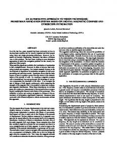
Paper #1446 (34) (35) (36) (37) (38) (39) (40) (41) (42) (43) (44) (45) (46) (47) (48) (49) (50) (51) (52) (53) (54) (55) (56) (57) (58) (59) (60) (61) (62) (63) (64) (65) (66) (67) (68) (69) (70)
quantity vd across td to tb; quantity vs across ts to tb; quantity ids through td to ts; -- thermal branch quantities quantity gpower through thermal_ref to tj; quantity temp across tj to thermal_ref; function i_v (constant v: real) return real is variable x: real; begin return (log(1.0 + 0.5*exp(v)))**2; end function i_v; function f_id (temp, vg, vs, vd: real) return real is variable id, vt, ratio, eg, egref: real; variable vto_th, kp_th: real; variable vgprime_0, vgprime, vp, iff, irr, beta, n: real; begin vt := KOQ*temp + 1.0e-6; ratio := abs(temp/TEMPREF + 1.0e-6); vto_th := MTYP*(VT0 - TCV*(temp - TEMPREF)); kp_th := KP*(ratio**BEX); vgprime_0 := vg - vto_th + PHI + GMA*sqrt(PHI); vgprime:=0.5*(vgprime_0+sqrt(vgprime_0*vgprime_0+1.0e-3)); vp := vgprime - PHI - GMA*(sqrt(vgprime + 0.25*GMA*GMA) - 0.5*GMA); iff := i_v((vp - vs)/vt); irr := i_v((vp - vd)/vt); beta := kp_th*(WEFF/LEFF)*(1.0/(1.0 + THETA*vp)); n := 1.0; return 2.0*n*beta*vt*vt*(iff - irr) + 1.0e-10; end function f_id; begin ids == MTYP*f_id(temp, MTYP*vg, MTYP*vs, MTYP*vd); gpower == abs(ids*(vd - vs)); end architecture ekv_simple;
Fig. 10. VHDL-AMS model of a simple EKV MOS model.
2) Verilog-AMS Description The Verilog-AMS source code for the CMOS inverter is given in Fig. 11. It is also a structural model that instantiates two MOSFET transistor components. Both the generic parameter and the port associations use the named association mechanism for improved readability. Note that the include statement in line 3 should be typically inserted in the top-level model of the airbag system only. Including the same file in several places is a common mistake and compiler directives are usually included to prevent this. Fig. 12 gives the Verilog-AMS model of the simplified EKV MOST model. The use of an analog block is natural here as the EKV model is inherently procedural (lines 32 to 53). Local variables to hold terminal voltages are used in the block (lines 33 to 35). This is done to avoid scattering access functions throughout the code and also to use the right signs depending on the MOS type. A utility macro “I_V” is defined to realize a smooth interpolation function (line 4). The macro is expanded in-line in the code with the appropriate parameter substitution (lines 45 and 46). Note the use of the predefined limexp function, which implements an exponential function whose value is limited during the solution iterations. This is
11 very useful to prevent arithmetic overflow in intermediate computations that may typically occurs in semiconductor models. At the end of the analog block, the computed drain current id is assigned as a flow contribution between the td and ts electrical terminals (line 50), and the self-heating heat is assigned as a flow contribution to the thermal terminal tj through the Pwr()access function (line 52). The flow is defined from the thermal ground, as declared in lines 9 and 10 to the terminal tj. (1) (2) (3) (4) (5) (6) (7) (8) (9) (10) (11) (12) (13) (14) (15) (16) (17) (18) (19) (20) (21) (22) (23) (24) (25) (26) (27) (28) (29) (30) (31) (32) (33) (34) (35) (36) (37)
`include "disciplines.h" `include "mos_ekv_simple.v" module cmos_inv (tin, tout, tjn, tjp, tvdd, tvss); inout tin, tout, tjn, tjp, tvdd, tvss; electrical tin, tout, tvdd, tvss; thermal tjn, tjp; parameter real WP = 60u; parameter real WN = 30u; parameter real LP = 0.15u; parameter real LN = 0.15u; mos_ekv
#(.MTYP(-1.0), .WEFF(WP), .LEFF(LP), .VT0(-0.4), .TCV(-1.5m)) mp (.td(tout), .tg(tin), .ts(tvdd), .tb(tvdd), .tj(tjp));
mos_ekv
#(.MTYP(1.0), .WEFF(WN), .LEFF(LN), .VT0(0.4), .TCV(1.5m)) mn (.td(tout), .tg(tin), .ts(tvss), .tb(tvss), .tj(tjn)); endmodule // cmos_inv
Fig. 11. Verilog-AMS structural model of the CMOS inverter. (1) (2) (3) (4) (5) (6) (7) (8) (9) (10) (11) (12) (13) (14) (15) (16) (17) (18)
`include "disciplines.h" `include "constants.h" `define I_V(v) pow(ln(1.0 + 0.5*limexp(v)),2) module mos_ekv (td, tg, ts, tb, tj); inout td, tg, ts, tb, tj; electrical td, tg, ts, tb; thermal tj, th_gnd; ground th_gnd; parameter real MTYP = 1.0; // NMOS: 1.0, PMOS: -1.0 // geometrical parameters parameter real WEFF = 1.0e-6; // effective channel width parameter real LEFF = 0.15e-6; // effective channel length // threshold voltage and substrate body effect parameters parameter real VT0 = 0.4; // long channel threshold voltage parameter real PHI = 0.97; // bulk Fermi potential
Paper #1446 (19) (20) (21) (22) (23) (24) (25) (26) (27) (28) (29) (30) (31) (32) (33) (34) (35) (36) (37) (38) (39) (40) (41) (42) (43) (44) (45) (46) (47) (48) (49) (50) (51) (52) (53) (54)
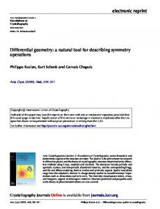
parameter real GMA = 0.71; // body effect parameter // mobility parameters parameter real KP = 453.0e-6; // transconductance parameter parameter real THETA = 50.0e-3; // mobility reduction coefficient // temperature coefficients parameter real TCV = 1.5e-3; // temp. coef, of threshold voltage parameter real BEX = -1.5; // temp. coef. of transcond. param. real vt, temp, tempref, ratio, eg, egref; real vto_th, kp_th, vgprime_0, vgprime, vp; real vg, vs, vd; real iff, irr, beta, n, id, gpower; analog begin vg = MTYP*V(tg, tb); vs = MTYP*V(ts, tb); vd = MTYP*V(td, tb); tempref = 300.15; temp = Temp(tj); vt = `P_K*temp/`P_Q + 1.0e-6; ratio = abs(temp/tempref + 1.0e-6); vto_th = MTYP*(VT0 - TCV*(temp - tempref)); kp_th = KP*pow(ratio,BEX); vgprime_0 = vg - vto_th + PHI + GMA*sqrt(PHI); vgprime =0.5*(vgprime_0+sqrt(vgprime_0*vgprime_0+1.0e-3)); vp = vgprime - PHI - GMA*(sqrt(vgprime + 0.25*GMA*GMA) - 0.5*GMA); iff = `I_V((vp - vs)/vt); irr = `I_V((vp - vd)/vt); beta = kp_th*(WEFF/LEFF)*(1.0/(1.0 + THETA*vp)); n = 1.0; id = MTYP*2.0*n*beta*vt*vt*(iff - irr) + 1.0e-10; I(td, ts) ith_eff then return eta_eff*(id - ith_eff); else return 0.0; end if; end function lightpwr; begin id == idval(temp, vd); power == id*vd; lpwr == lightpwr(temp, id); olight == lpwr'ltf((0 => 1.0), (0 => 1.0, 1 => TAU)); end architecture bhv;
Paper #1446 Fig. 15. VHDL-AMS model of the laser diode.
14 (46)
end architecture bhv;
Fig. 17. VHDL-AMS model of the photo-diode. (1) (2) (3) (4) (5) (6) (7) (8) (9) (10) (11) (12) (13) (14) (15) (16) (17) (18) (19) (20)
library ieee_proposed; use ieee_proposed.energy_systems.all; entity xmedium is generic ( XDEL : real := 5.0*NANO; -- transmission delay XCOEF: real := 0.5 -- reduction coefficient ); port ( quantity lin : in real; quantity lout: out real ); end entity xmedium; architecture ideal of xmedium is quantity qin: real; begin qin == lin; -- 'delayed on port qties not yet supported lout == XCOEF*qin'delayed(XDEL); end architecture ideal;
Fig. 16. VHDL-AMS model of the transmission medium. (1) (2) (3) (4) (5) (6) (7) (8) (9) (10) (11) (12) (13) (14) (15) (16) (17) (18) (19) (20) (21) (22) (23) (24) (25) (26) (27) (28) (29) (30) (31) (32) (33) (34) (35) (36) (37) (38) (39) (40) (41) (42) (43) (44) (45)
library ieee; use ieee.math_real.all; library ieee_proposed; use ieee_proposed.energy_systems.all; use ieee_proposed.electrical_systems.all; use ieee_proposed.thermal_systems.all; entity photo_diode is generic ( CD : real := 1.0*PICO; -- diffusion capacitance RLEAK : real := 1.0*MEGA; -- leakage resistance SENSITIVITY: real := 0.13; -- diode sensitivity IDARK0 : real := 1.0*NANO; -- dark current at nominal temp. IDARK_DT : real := 45.0; -- temperature variation COOLINGG : real := 1.0*MILLI –- cooling conductance ); port ( quantity ilight : in real; terminal tan, tca: electrical; terminal tj : thermal ); end entity photo_diode; architecture bhv of photo_diode is quantity vd across id through tan to tca; quantity power through thermal_ref to tj; quantity temp across tj to thermal_ref; quantity tempc, idark, ip, ic, ir: real; begin tempc == temp - 273.0; ir == vd/RLEAK; idark == IDARK0; ic == CD*vd'dot; ip == -SENSITIVITY*ilight; id == idark + ip + ic + ir; power == abs(id*vd) + (tempc*COOLINGG - ilight);
2) Verilog-AMS Description The Verilog-AMS source code for the laser diode is given in Fig. 18. The model interface has two electrical ports tano and tcat, one thermal port tj and one optical port olight (lines 4 to 9). Verilog-AMS uses a simplified discipline definition for modeling signal-flow ports. Since there is no predefined signal-flow optical discipline in the disciplines.h file, we have to define our own in the model. The following code gives the discipline definition: nature Illuminance units = "Cd"; access = LP; `ifdef CHARGE_ABSTOL abstol = `CHARGE_ABSTOL; `else abstol = 1e-14; `endif endnature discipline optical_sf potential Illuminance; enddiscipline
The optical_sf discipline definition is stored in a file named optical_sf.v, which is included in the top-level airbag system model since three models are using the discipline. Light is then described by a potential (Illuminance) and managed by the access function LP(). In the model body, one can notice the call to the cross function without the execution of any related statement (line 30). The goal is to force the analog simulation kernel to have a simulation point inserted at the time of the crossing and then to accurately switch between the two possible expressions for the lightpwr variable (lines 31 and 32). The contribution to the light output is expressed through the Laplace filter laplace_nd as given by (4) (line 34). The Verilog-AMS model of the transmission medium is given in Fig. 19. The model interface is purely signal-flow (lines 1 to 4) and the model body makes use of the predefined function transition to implement the fiber delay (line 9). Verilog-AMS does also support the function absdelay but it is not used here as it would force too many simulation timepoints. It has to be noted, however, that the transition function is used without rise or fall times to again avoid too many simulation time points. The price to pay is a less accurate output waveform, although still meaningful at the system level. The Verilog-AMS model of the photo-diode is given in Fig. 20. As for the laser diode model, the model interface includes one signal-flow port for the light input, two electrical
Paper #1446 ports for the anode and the cathode, and one thermal port for the thermal interactions (lines 1 to 8). The model body implements the temperature dependency of the dark current and the model of Fig. 14. Instead of using the variable id in line 25, it could have been possible to use the contribution operator ith_eff) lightpwr = eta_eff*(id - ith_eff); else lightpwr = 0.0; LP(olight)