Vibration Control of a High-Speed Precision Servo Numerically
Recommend Documents
Keywords: technological robots; servo drives; impedance control; high precision; backlash; two motors servo drive. This Publication has to be referred as: ...
HighSpeed TCP/RED network and use it to study its per- formance. The main ..... [4] T. Kelly, Scalable TCP: Improving Performance in. Highspeed Wide Area ...
control-systems-principles.co.uk. Servo Control Systems 1: DC Servomechanisms the angular velocity
Barbalat's Lemma [62] can then be used to prove the result given in (33). Based on the controller in (26) and (27) and the adaptive law in (28), the resulting ...
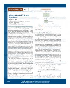
PROJECT FOR SECTION 3.11 Vibration Control: Vibration Absorbers ... tion
absorber is in essence a spring/mass system attached to the structure. Therefore
we ...
Machine Vision, and Servo Control manuals can be completed ... Modify the PLC
program to make the Part Feeder follow the Flat Belt ... Start RSLogix 5000.
Sep 15, 2016 - Active vibration control is an effective way to suppress both the structural ... with an LQR feedback motion controller is developed by. Deng et al.
Block Diagram of a Position Controlled Hydraulic Servo System. ... Cross-
sectional Diagram of Double-ended, Double-acting Linear Actuator . ..... into
those in which hydraulic pressure is applied to one side of the piston only (single
acting).
digital signal processor (DSP) is adapted to ultrasonic motor drive system. The speed control of ... the electrical equivalent circuit model of the TWUSM is de- rived from the motor .... The block diagram of TMS320F243 controlled USM ... two-phase ha
M. F. Wu, R. U. Mendes, K. L. Cavalca, ABCM, São Sebastião, SP, Brazil, March 5-10, 2017. Vibration Control ... [email protected]. 2 rumqld@gmail.
Jul 19, 2013 - devices like sensors and actuators that may either be embedded ... Keywords: Smart cantilever beam, active vibration control, direct output ...
rotating shaft with nonlinear spring characteristics. Ganesan (1996) studied ... backward whirling mode in addition to the forward one. Furthermore ... and horizontal directions that depend on the magnitude of the rotor ..... controllers that are con
May 5, 2017 - transmission tower in the longitudinal and transverse directions. The reduction ratio increases with the increase of the mass ratio. .... Ug(t) is the input ground motion acceleration in two horizontal directions; and P(t) is the poundi
robot, are utilized to design a dynamic image based visual servo controller. A nonlinear ... controller for high speed tasks and underactuated robots is reported in ...
For further references see, Automation control systems by B.C. Kuo and Linear
control system by B.S. Manke. Fig 2: Set of speed – torque curves (theoretical) for
...
26 Sep 2010 ... The main objective of the direct adaptive NNFBL ... direct adaptive control,
feedback linearization control, PID control, ride comfort, suspension.
Apr 1, 2013 - Zhipeng Zhang, Member, IEEE, Fei Long, and Chia-Hsiang Menq, Senior Member, IEEE. AbstractâThis paper presents the development of a ...
A real-time simulator is utilized to control a hydraulic position servo system. In this control .... pressure sensors, and a single displacement sensor. Voltage u(V) is ...
School of Mechanical Aeronautical ... Active vehicle suspension control problem is a disturbance rejection ... a trade-off between these requirements is needed.
To achieve a fully autonomous robot several individual sensory based ..... This
paper presented the development of a mobile robot system guided by an.
KaMeWa Group, a Vickers company who manufactures water jet propulsion ...
head to the water via the impeller and then let the water go through a guide vane.
Nov 8, 2010 - points in [0, ] such that 0 ¼ 0 < 1 < ءءء < N ¼ . The continuous space X is replaced by the space XN of the discrete functions defined on the ...
Nov 28, 2014 - different severity in a freeâfree uniform rod under lon- gitudinal vibration. We show that the .... where L is the length of the beam. Assuming that ...... by (64), (65), (67) and (68) we obtain the following system of four nonlinear
Vibration Control of a High-Speed Precision Servo Numerically
Nov 21, 2016 - structural design is unreasonable or the rigidity of the press is insufficient [3, 4]. .... where 1 is the mass of the crank-connecting rod-slider.
Hindawi Shock and Vibration Volume 2017, Article ID 4593546, 17 pages https://doi.org/10.1155/2017/4593546
Research Article Vibration Control of a High-Speed Precision Servo Numerically Controlled Punching Press: Multidomain Simulation and Experiments Teng Xu,1 Qinxiang Xia,1 Xiaobin Long,2 and Gianluca Buffa3 1
1. Introduction A heat-transfer fin is a component which is widely applied in the heat exchangers of air conditioners, refrigerators, and automobiles and is usually installed on the surface of the heat exchanger to increase the heat exchange efficiency by increasing its surface area [1]. Materials normally used for manufacturing heat-transfer fins are copper and aluminous foils, ranging in thickness from 0.1 to 0.15 mm [2]. Heattransfer fins are commonly manufactured using a highspeed numerically controlled (NC) punching press with a multiposition progressive die. Serious vibration occurs readily during the manufacture of the heat-transfer fins owing to the complexity of the structure and high frequency of stroke of the high-speed NC punching press when the structural design is unreasonable or the rigidity of the press is insufficient [3, 4]. Forming defects, such as fractures and wrinkling during the stamping of heat-transfer fins, are induced by even a slight vibration of the press because of the
thin walled structure of the fin. Additionally, the vibration of the punching press adversely affects the service life of the punching press and the progressive stamping die, as well as the operational environment of the workshop [5]. With the continuous development of punching presses, vibration issues have become more diverse and complex, and the integrality of a punching press has gradually been considered in studies aimed to the determination of their capabilities. Vibration problems of punching presses are closely related to mechanical, servomotor, NC control, and hydraumatic subsystems. Hence, single-disciplinary modeling and simulation cannot satisfy all the complex requirements needed for proper design of a punching press. During the conventional simulation of NC equipment, various software, supported by the theories of different disciplines, are adopted to establish models of electronic, hydraulic, and dynamic subsystems, making simulation research inefficient. Additionally, the separate modeling in different software results in deviation of the analysis of system integration [6, 7].
2
Shock and Vibration Hydraulic cylinder Up crossbeam Lead screw Movable cross beam Crank seat Crank shaft Connecting rod Gear set
the high-speed punching press considered in this study, including an upper crossbeam, side column, lower crossbeam, movable crossbeam, servomotor, gear set, slider, two crankshafts, four connecting rods, four lead screws, and four hydraulic cylinders. The torque generated by the servomotor is transmitted to the crankshafts through the gear set, and the lead screws are driven by the revolving crankshafts, resulting in the reciprocating movement of the slider. A multistation progressive stamping die is installed on the punching press to complete the stamping of the heat exchanger fin [13] as shown in Figure 2.
Considering the effect of each subsystem on the integral whole system of the complex punching press, the multidomain modeling method assembles models from different disciplines into a large integral model [8], which greatly improves the simulation efficiency. In this way, the problem of obtaining a numerical solution from data exchange among different software can be completely avoided. A multidomain modeling and simulation method has become crucial to improve NC mechanical products [9]. Bi and Liu [10] analyzed the kinematic situation of each axis of a six-axis robot employing a multidomain modeling and simulation method. Cao and Wu [11] proposed the multidomain modeling of a certain NC milling machine including mechanical and electronic components as well as a controller, using the simulation platform Dymola and the modeling language Modelica and predicting the motion path of the principal axis. Wang et al. developed a multidomain uniform model of a banana picking manipulator by virtual simulation and modeling language Modelica. The motion performance of the body structure, driven by a motor, was analyzed using a uniform model [12]. To the authors’ knowledge, there is no paper in literature focused on vibration analysis of high-speed punching presses through multidomain modeling and simulation. In the present study, to address the aforementioned vibration problem, a mathematical model of vibration and multidomain models of a punching press were established. Dynamic characteristics of the punching press were predicted in the multidomain simulation. Structural modification of the frame and improvement of the foundation were carried out to reduce vibrations. Once validated against experimental measurements, the multidomain model was used to discuss the influencing factors of vibrations under different conditions.
2. Vibration Modeling of a High-Speed Precision Punching Press 2.1. Structural Synthesis of a High-Speed Precision Punching Press. Figure 1 shows the closed four-point structure of
2.2. Vibration Mechanical Model. The frame of the punching press includes the upper crossbeam, side column and lower crossbeam. These parts are made of nodular cast iron and are connected using screw bolts and nuts. The crank-connecting rod-slider mechanism is the main transmission assembly of the punching press shown in Figure 1. As the levels of stiffness of the connecting rods, lead screws and subsoil are much lower than those of other components of the punching press, only the stiffness and damping of these three components are considered in this study. The following simplifications are introduced into the vibration mechanical model of the punching press [14–16]: (1) The frame is considered a rigid block, and the crankconnecting rod-slider mechanism is simplified as an assembly of a rigid block with linear springs and viscous damping, for which the stiffness and damping of the connecting rods are considered. The movable crossbeam and the crank seat are modeled as rigid blocks. The lead screws are considered as linear springs with stiffness and damping parameters. (2) Contact between the frame and subsoil under the punching press is taken into account by linear springs with viscous damping. Multidegree vibration models of servopresses were established by Lin [17] and Guo [18] et al. These presses are generally considered as a mass-spring-damper system with one degree of freedom (DOF), ignoring the stiffness and damping of connection parts among components. The present study establishes a mass-spring-damper vibration system with three DOFs of the punching press (see Figure 1) as shown in Figure 3, considering the relative motion between the slider and frame. According to the structure of the punching press and the mechanical analysis of the stamping, under the condition of zero-load operation, a periodic and compound exciting force 𝑚𝑒𝜔2 sin 𝜔𝑡 [19], generated by the reciprocating motion of the slider [20], is imported to the crankshaft through the gear sets, without loading a stamping force on the punching press. The three-DOF motion differential equations of the punching press under the condition of zero-load operation are thus expressed by (1). Under the condition of stamping, both 𝑚𝑒𝜔2 sin 𝜔𝑡 and the stamping force 𝑝(𝑡) act on the punching
Shock and Vibration
3 I
|B
A
A-A 3:1
II
11.8 10.4 ± 0.03
III
A
12.6
|B III revolve
II revolve 3:1
2×
9
I 3:1
3:1 12.4 11.0 ± 0.03 7 R0. R0.3 13.2
.5 R7
1 3 7 11 15 17
2 18 25.4
2
6.35 ± 0.03
B-B
0.115
44
25.4 ± 0.03
22 ± 0.03
12.7 ± 0.03
Figure 2: Heat exchanger fin.
𝑚3 𝑥̈ 3 + 𝑘3 𝑥3 + 𝑐3 𝑥̇ 3 + 𝑘2 (𝑥3 − 𝑥2 ) k2
k1
m2
c2 c1
+ 𝑐2 (𝑥̇ 3 − 𝑥̇ 2 ) = 𝑝 (𝑡) , (2)
x2
m1 p(t)
x1
p(t) m3 k3
c3
x3
Figure 3: Three-DOF vibration model of a high-speed punching press.
press, and the three-DOF motion differential equations are expressed by
where 𝑚1 is the mass of the crank-connecting rod-slider mechanism; 𝑚2 is the mass of the movable crossbeam and the crank seats; 𝑚3 is the mass of the frame and the lower crossbeam; 𝑚 is the mass of the slider, which is part of 𝑚1 ; and 𝑒 and 𝜔 are the eccentric distance and the rotational speed of the crankshaft, respectively. 𝑘𝑙 and 𝑐1 , 𝑘2 and 𝑐2 , and 𝑘3 and 𝑐3 are the equivalent stiffness and damping of the connecting rod, lead screws, and subsoil under the punching press, respectively. The differential equations in (1) are solved to obtain analytic expressions for 𝑥1 , 𝑥2 , and 𝑥3 , which are the vibratory quantities of the slider, movable crossbeam, and frame of the punching press shown in Figure 3. Numerical solutions of (1) are as follows:
Table 1: Parameters of mass-stiffness-damping system of the punching press.
𝜆2 [ [sin (𝜔𝑡 − 𝜑3 ) 𝜔√Δ 2 [
𝜉22
𝑖 1 2 3
] sin (𝜔𝑑2 𝑡 − 𝜑4 )] ,
𝜆3 [ [sin (𝜔𝑡 − 𝜑5 ) 𝜔√Δ 3 [ 𝜆3
√1 −
𝜉32
(𝑘𝑖 /N⋅m−1 ) 1.53 × 10¹⁰ 6.35 × 10⁹ 6.71 × 10⁷
(𝑚𝑖 /kg) 2522 3822 12800
]
] sin (𝜔𝑑3 𝑡 − 𝜑6 )] ,
(×10−3 m)
𝑦2 (𝑡) = 𝑚𝑒𝜔2
] (4)
where 𝜔𝑖 is the natural frequency [20] of the three-DOF vibration model shown in Figure 3, 𝜔𝑑𝑖 is the damped natural frequency [19], which can be expressed as 𝜔𝑑𝑖 = 𝜔𝑖 √1 − 𝜉𝑖2 , 𝜉𝑖 being the damping ratio, 𝜉𝑖 = 𝑐𝑖 /2√𝑘𝑖 𝑚𝑖 ; 𝜆 𝑖 = 𝜔/𝜔𝑖 and Δ 𝑖 = (1 − 𝜆2𝑖 )2 + 4𝜉𝑖2 𝜆2𝑖 . 𝑘𝑖 , 𝑐𝑖 , and 𝑚𝑖 shown in Figure 3 are given in Table 1 according to the structure of the punching press [20], where 𝜉1,2 belong to damping ratios of steel for engineering mechanism, which were assigned as 0.020 [21], 𝜉3 = 0.16/√𝑚, and 𝑚 is the total mass of the punching press and the foundation block [21, 22]. 𝑚, 𝑒, and 𝜔 were assigned as 𝑚 = 2076 kg, 𝑒 = 0.02 m, and 𝜔 = 300 rpm in the present study. Figure 4 shows the vibrational curves of the slider and frame under the condition of zero-load operation, according to (1) and (4), developed with the mathematical processing software Matlab. According to the stiffness and damping given in Figure 3, vibration amplitudes of the slider and frame were 1.222 and 1.206 mm, respectively (see Figure 4), which are to be compared with the predictions of the multidomain model established in the following.
3. Multidomain Models of the High-Speed Precision Punching Press A multidomain model of the punching press was established (see Figure 5) considering the structure and vibration model, and a physical object-oriented modeling method was selected and developed using the multidomain system dynamics platform SimulationX. During the physical object-oriented modeling, physical relationships are established through a potential and flow rate; specifically, each node in the model contains a series of potential rates, and each connecting interface that links to the same node contains the same number of potential rates. All the flow rates in the model satisfy the balance equations. In this study, the multidomain model of the punching press was composed of subsystems for the mechanism, servomotor, and stamping die. The mechanical subsystem consisted of the frame, movable crossbeam, gear sets, slider, lead screws, crankshaft-connecting rod mechanisms, and the connecting joints between mechanisms. The
Figure 4: Analytical curves of the vibration of the slider and frame under the zero-load operating condition.
subsystem of the stamping die consisted of the progressive stamping die and the stamping forces generated during the forming of the heat exchanger fin. The mechanical subsystem was connected to the subsystem of the servomotor through the gear set. The rotation speed of the servomotor was preset at a constant value in the preprocessing of the simulation. A three-dimensional model of each component of the punching press was imported into the SimulationX platform using the CAD-import element. Motion transmission between the components was obtained by a set of revolving-joint and sliding-joint elements. Engaging forces generated by the gear sets were guided and imposed on the movable crossbeam using an actuated prismatic joint element. Spring damping elements were employed to model connecting parts according to the vibration model (see Figure 3). Several groups of equal and opposite stamping forces were set in the subsystem of the stamping die, according to the stamping condition of the punching press. Figure 6 shows the progressive stamping die [13] adopted to manufacture the heat exchanger fin (see Figure 2), and the theoretical force of each stamping position is given in Table 2 [13]. The stamping forces were imposed at each relevant position of the upper and lower die simultaneously during the simulation, as shown in Figure 5, in accordance with the blank layout (see Figure 7) of the heat exchanger fin and dimensions of the working positions. The frequency of strokes during stamping was 300 strokes per minute, and the transmission ratio of the gear sets was 1 : 5; therefore, the rotational speed of the servomotor was
Shock and Vibration
5 Hydraulic pressures
Stamping forces
Hydraulic system
Servomotor
Movable crossbeam Crankshaft-connecting rod Frame Foundation soil Slider progressive die
Crankshaft-connecting rod
Hydraulic system
Stamping force curves
Stamping forces (a) Element structure view
Upper die
Lower die
(b) Three-dimensional view
Figure 5: Multidomain model of the high-speed precision servo punching press based on SimulationX.
preset at 1500 r/min. The length of the eccentric arm of the crankshaft was 20 mm, and the length of the connecting rod was 400 mm. An EMB-1ED A15 synchronous servomotor was used to drive the servo punching press. Technical parameters of the servomotor are given in Table 3. A model of the servomotor consisting of a speed loop, current loop, and additional position loop (i.e., three-loop control of the servomotor) was set up.
4. Multidomain Simulation of the High-Speed Precision Punching Press The crankshaft-connecting rod mechanisms of the servo punching press in Figure 1 can be simplified as the typical crank-slider mechanism shown in Figure 8. Point 𝑂 is the rotation point of the crank, and points A and B are the connection point between the connecting rod and crank and the connection point between the connecting rod and slider, respectively. Angle 𝛼 is the angular rotation of the crank. The stroke of the slider is a variable depending on the stiffness and the damping factor of the lead screws, connecting rods,
Figure 6: Multistation progressive stamping die for the heat exchanger fin.
and subsoil below the punching press. A coordinate system was established, in which the top dead centers of the slider and frame were considered the initial points in each motion period (as shown in Figure 8). Operational motions of the slider and frame were predicted in multidomain simulation with the aim to calculate the vibration quantity of the punching press. Figure 9 shows the calculated acceleration curve of the slider under the condition of zero-load operation. The acceleration amplitude of the slider decreased during the starting period of the punching press, as shown in Figure 9,
Stamping force (kN) Distance from left side of die holder (mm)
Figure 10: Curves of the simulated rotational speed of the crankshaft and displacement of the slider.
40
(m/s2 )
20 0 Transition
−20 Starting
Steady
−40 0
2
4
6
8
10
12
(s)
Figure 9: Simulated acceleration curve of the slider under the condition of zero-load operation.
because large current was generated by the servomotor to produce large torque to overcome the resistance that acted on the crankshaft-connecting rod mechanism at the starting moment (i.e., at a time of 0 s), while the suddenly imposed large torque resulted in vibration in the punching press (where the acceleration amplitude of the slider was about 15 m/s2 ). After the starting phase, resistance acting on the crankshaft-connecting rod mechanism instantly decreased, reducing the torque and current produced by the servomotor, as well as the acceleration amplitude of the slider (Figure 9).
The stroke frequency of the slider increased rapidly in the transition period, increasing the reciprocating inertial force and the acceleration of the slider (where the acceleration increased to about 40 m/s2 ). As shown in Figure 9, approximately 12 s after the starting of the punching press, the slider reached a steady state and the stroke frequency reached 5 strokes per second (or 300 strokes per minute). Figure 10 shows the simulated rotational speed curve of the crankshaft and the displacement of the slider under the condition of zero-load operation. When the slider passed through the equilibrium position of its reciprocating motion, the rotational speed of the crankshaft had an average value of 300 r/min, as shown in Figure 10. Because of gravitational effects, the speed of the slider increased after the slider passed through its equilibrium position during the down stroke, and the rotational speed of the crankshaft became maximum. During the upstroke, the slider started from the bottom dead center, and the speed of the mechanism decreased because of gravity, where the rotational speed of the crankshaft decreased to a minimum before the slider reached its top dead center. Afterward, the servomotor accelerated to drive the crankshaft rotation at a constant speed, so as to overcome the gravitational effects and make the slider reach
8
Shock and Vibration 0
−3
−40
−2.185
−50 −60
0∘
90∘
180∘
270∘
360∘ (𝛼)
450∘ 540∘
630∘ 720∘
slider.x frame.x
−2
−20 (mm)
−30
−1
−22.753
−30 1.177
−2
(mm)
−1
−22.761
0
1.162
0
(mm)
(mm)
−20
−10
21.124
−10
21.117
1
0
−40
−3
−50
−4
−60
−2.812
0∘
90∘
180∘ 270∘
360∘ (𝛼)
450∘
540∘ 630∘ 720∘
slider.x frame.x
(a) Displacement curves of the frame and slider under the condition of zeroload operation
(b) Displacement curves of the frame and slider under the condition of stamping
Figure 11: Displacement curves of the frame and slider without the installation of foundation.
its top dead center. The rotational speed of the servomotor increased to a peak value when the slider reached its top dead center. The speed of the slider increased after starting from the top dead center until its equilibrium position owing to the positive work due to gravity and, during that time, the required torque and the rotational speed generated by the servomotor decreased. As mentioned above, the rotational speed of the crankshaft was preset as a constant value in the vibration model of the punching press (see Figure 3). The electromechanical coupling of the servomotor and the motion mechanism was considered in the multidomain model, as seen in Figure 10. Hence, the rotational speed of the servomotor fluctuated owing to the change in the external load. Meanwhile, the vibration of the slider and frame was induced by the fluctuation of the servomotor. As already mentioned, the crankshaft-connecting rod mechanism of the punching press was modeled as the typical crank-slider mechanism, shown in Figure 8, where the rotational speed 𝜔 of crank 𝑂A corresponds to the rotational speed of the crankshaft as shown in Figure 10, and 𝜔 was one-fifth of the simulated speed of the servomotor. A is the point of connection between the crank and connecting rod, as shown in Figure 8, the tangential speed V of A is induced by the rotational speed 𝜔, and the vertical component V𝑦 of V equals the speed of the slider. The relationship between V𝑦 and V is expressed as follows: V=
V𝑦 sin 𝛼
.
(5)
Equation (5) reveals that, except in the situation that the slider passes through its top and bottom dead center, to guarantee a constant speed of the slider, the required rotational speed of the crankshaft is a minimum when the slider passes through its equilibrium position (Figure 8). This paper explores the vibration of the punching press simulated using the multidomain model and obtains the relative vibration between the frame and slider under the condition of zero-load operation and stamping to judge the working performance of the punching press. Figure 11 shows
the displacement-time curves of the slider and frame, in which initial gravity centers of these two components are the zero points. Figure 11(a) reveals that, under the condition of zeroload operation, the frame vibrated with an amplitude of 1.162 mm, and the gravity center of the frame shifted down to an equilibrium position of −2.815 mm. The amplitude of the reciprocating motion of the slider was 21.124 mm (the theoretical value of which is 20 mm, according to the length of the eccentric arm of the crankshaft), at an equilibrium position of −22.761 mm. It is worth noticing that the theoretical amplitude of the slider of 20 mm should be subtracted in calculating the vibratory quantity. Compared with the theoretical analytical curves shown in Figure 4, relative errors of the predicted vibration amplitudes of the slider and frame were 7.83% and 7.45%, as shown in Figure 11(a). Because the weights of the components are not considered in (1), differences in equilibrium positions of the slider and frame are not presented in Figure 4. As shown in Figure 11(b), under the condition of stamping, the equilibrium position of the reciprocating motion of the slider was −22.753 mm, and the amplitude of the motion was 21.117 mm. The frame vibrated with an amplitude of 1.177 mm, at an equilibrium position of −2.812 mm under the condition of stamping. According to the above results, the relative distance between the equilibrium positions and the difference in amplitude of the slider and frame can be calculated as 0.059 and 0.060 mm, respectively, and the relative vibration between the frame and slider under the condition of stamping was 0.119 mm, which was larger than the thickness of the workpiece of the heat exchanger fin (0.115 mm). The comparison reveals that the working performance of the punching press needs to be further enhanced.
5. Experimental Investigation and Verification Experimental measurements were made to validate the model. Acceleration, which is proportional to the vibration amplitude of a certain mechanism during its vibration [19], is
Shock and Vibration
9
CA-YD-127 piezoelectric accelerometer (8 ones)
DH5923 dynamic signal analysis system
Figure 12: Experimental measurements of the acceleration of main components.
5 6 7 1
2
3
4
(a) Front side view
(b) Reverse side view
8
Figure 13: Arrangement of accelerometers on the punching press.
an important index that represents the intensity of vibration. A DH5923 dynamic signal analysis system was adopted to measure the acceleration of the frame, movable crossbeam, and slider (see Figure 12), under the condition of zero-load operation for different rotational speeds of the servomotor. Figure 13 shows the arrangement of CA-YD-127 piezoelectric accelerometers on the punching press. In the Figure, the plane on which the gear sets are installed is referred to as the front side of the punching press, and the opposite plane is the reverse side. Table 4 compares the experimental and
theoretical values of acceleration of the main components of the punching press. Owing to the effects of external disturbances such as vibration and noise, the experimental acceleration was greater than the acceleration predicted by simulation. Values measured by accelerometers numbers 3, 4, 7, and 8 represented acceleration of the frame. Values recorded by accelerometers numbers 7 and 8 were higher than those recorded by accelerometers numbers 3 and 4 because the former were installed on the side column, the acceleration of which is more susceptible to the reciprocating inertia force
10
Shock and Vibration Table 4: Experimental and theoretical values of acceleration of main components for different speeds of the servomotor (m/s2 ).
of the slider. The maximum relative error is about 21%, as listed in Table 3, indicating that the experimentally measured acceleration is consistent with the simulation results obtained in this paper. The validity and rationality of the multidomain model and three-DOF vibration model of the high-speed precision servo punching press were verified by the comparison of results. The simulation curves represent kinematic motions of the geometrical centers of the components of the punching press investigated in this study. As shown in Table 4, due to the effects of the installation position of the gear sets, values of acceleration recorded by the accelerometers installed on the front side, on which the gear sets are installed as shown in Figure 13(a), were generally larger than those recorded by accelerometers installed on the reverse side (see Figure 13(b)). Torque and torsional vibration of the gear sets were transferred to the movable crossbeam and crankshaft and subsequently to the slider, side column, and lower crossbeam, resulting in the vibration of these components, which increased with the rotational speed of the gear sets. Because the accelerometers were installed on the surfaces of these components, there was additional consumption of vibration during its transferring, and there were differences between values measured using the accelerometers installed in different areas of the same component, as shown in Table 4. Figure 14 compares the experimentally measured and simulated curves of the acceleration of the slider under the condition of zero-load operation, when the rotational speed of the servomotor was 600 r/min. Figure 14(a) shows that the maximum acceleration of the slider measured by accelerometer number 1 (see Figure 13) was 3.60 m/s2 . The maximum simulated acceleration of the slider was 3.46 m/s2 as shown in Figure 14(b). The maximum difference in the acceleration between the multidomain model prediction and experimental testing is 0.14 m/s2 , and the relative error is about 4.05%. Because of the speed fluctuations of the
Maximum relative error/% 17.4% 18.5% 16.6% 17.3% 13.2% 18.0% 15%
servomotor, vibration superposition of the components of the punching press, and other external environmental factors, the slider operated with a certain speed fluctuation relative to its desired speed. Therefore, there was fluctuation in the acceleration curves of the slider, as shown in Figure 14, in which the lower pass filter was set at 10 Hz [23, 24]. Figures 14(c) and 14(d) show the spectral analysis curves of the experimental and simulated acceleration of the slider shown in Figures 14(a) and 14(b) and the maximum amplitudes and the frequencies of which were, respectively, 2.838 m/s2 and 8.95 Hz and 2.812 m/s2 and 9.37 Hz. This reveals that the spectral compositions and energy distributions of the acceleration were basically consistent between the multidomain model prediction and experimental testing.
6. Modal Analysis of the Punching Press Table 5 gives the natural frequency of each order of vibration of the frame, slider, and movable crossbeam obtained in freedom modal analysis, where the natural frequency of vibration of the frame was a minimum. Low-order natural frequencies of a mechanism are generally more prone to being coupled with external excitations and have worse effects on the structure than high-order modes, thus determining the dynamic behavior of the mechanism [25]. The modes of the first six orders of vibration of the frame are shown in Figure 15. The first mode primarily reveals a single torsional vibration that occurs in the upper half of the frame. The second and third modes, respectively, reveal single flexural vibrations that occur in different directions. The fourth mode behaves as two flexural vibrations in the horizontal direction of the frame. The fifth mode reveals two torsional vibrations that occur around 𝑥- and 𝑦- axes as shown in Figure 15(c). The sixth mode also behaves as two flexural vibrations. The operating efficiency of the punching press during actual production is 300 cpm, and the frequencies of the punching
Shock and Vibration
11 Table 5: Natural frequencies of main components of the punching press (Hz).
Frame Movable crossbeam Slider
Mode Frequency Mode Frequency Mode Frequency
1 42.432 1 117.89 1 73.537
2 48.599 2 133.09 2 389.26
3 76.321 3 250.38 3 418.39
4 84.978 4 321.06 4 449.14
3.5
5 107.35 5 347.88 5 452.02
6 128.09 6 389.02 6 456.43
7 134.88 7 400.39 7 488.67
8 140.55 8 478.52 8 497.08
3 2
(m/s2 )
1 (m/s2 )
0
0 −1 −2
−3.5
−3 180∘
0∘
360∘
540∘ (𝛼)
720∘
900∘
1080 ∘
180∘
0∘
360∘
540∘ (𝛼)
720∘
900∘
1080∘
FFT (slider.a)
FFT (slider.a) (a) Curve of experimentally measured acceleration
(b) Curve of simulated acceleration
3 2 (m/s2 )
(m/s2 )
2.25
1.5
1
0.75 0 0
50
100
150
200
250
300
350
400
0
50
100
150
(Hz) FFT (slider.a) (c) Spectral analysis curves of experimental acceleration
200 (Hz)
250
300
350
FFT (slider.a) (d) Spectral analysis curves of simulated acceleration
Figure 14: Curves of experimentally measured and simulated acceleration of the slider under a rotational speed of the servomotor of 600 r/min.
press and servomotor are therefore 5 and 25 Hz, respectively. As shown in Figure 15(a), the fundamental frequency of vibration of the frame is 43.432 Hz, which is closer to that of the servomotor than to that of other components. This paper improves the structure of the frame to increase its fundamental frequency of vibration and thus avoid resonance between the frame and servomotor. Figures 15(a), 15(b), and 15(c) show that the maximum deformation areas for the first three vibration modes are distributed on the upper four corners of the frame. To increase the natural frequency of the frame, the welding ribbed slabs of the side columns were widened from 120 to 215 mm (see Figure 16(a)) and lateral plates of the upper
Table 6: Natural frequencies of the frame after modification (Hz). Mode Frequency
1 57.04
2 65.09
3 106.19
4 137.02
5 138.33
6 165.41
crossbeam were widened from 30 to 40 mm as shown in Figure 16(b), thus stiffening these areas. Additionally, welding strength beams were added around the upper corners of the frame as shown in Figure 16(c), to improve the stability of these corners. Each order of the natural frequency of the frame increased after the structural modification, as shown in Table 6.
12
Shock and Vibration
B: modal Total deformation 7 Type: total deformation Frequency: 42.432 Hz Unit: m 2015/11/6 21:50 0.026374 Max 0.023485 0.020596 0.017707 0.014819 0.01193 0.0090413 0.0061526 0.0032639 0.00037519 Min
B: modal Total deformation 8 Type: total deformation Frequency: 48.599 Hz Unit: m 2015/11/6 21:51
0.000 0.500 1.000 (m)
(a) First-order vibration mode
B: modal Total deformation 9 Type: total deformation Frequency: 76.321 Hz Unit: m 2015/11/6 21:54 0.015365 Max 0.013662 0.011959 0.010256 0.0085528 0.0068498 0.0051467 0.0034437 0.0017407 3.7646e − 5 Min
0.015388 Max 0.013778 0.012169 0.010559 0.008949 0.0073393 0.0057295 0.0041197 0.0025099 0.00090017 Min
0.000
0.500 (m)
1.000
(b) Second-order vibration mode
B: modal Total deformation 10 Type: total deformation Frequency: 84.978 Hz Unit: m 2015/11/6 21:56 0.021284 Max 0.018921 0.016558 0.014196 0.011833 0.0094699 0.0071071 0.0047443 0.0023815 1.8741e − 5 Min 0.000 0.500 1.000 (m)
0.000 0.500 1.000 (m)
(c) Third-order vibration mode
B: modal Total deformation 11 Type: total deformation Frequency: 107.35 Hz Unit: m 2015/11/6 21:58
(d) Fourth-order vibration mode
B: modal Total deformation 12 Type: total deformation Frequency: 128.09 Hz Unit: m 2015/11/6 22:23
0.045141 Max 0.040132 0.035123 0.030113 0.025104 0.020095 0.015085 0.010076 0.0050666 5.7242e − 5 Min
0.000 0.500 1.000 (m)
(f) Sixth-order vibration mode
Figure 15: Modes of the first six orders of vibration of the frame.
Shock and Vibration
13
Lateral plates Widening direction
Ribbed slab
Widening direction
(a) Modification of the side column
(b) Modification of the upper crossbeam
(c) Strength beams added around upper corners
B: modal Total deformation 2 Type: total deformation Frequency: 65.093 Hz Unit: m 2015/12/10 22:12
B: modal Total deformation Type: total deformation Frequency: 57.04 Hz Unit: m 2015/12/10 22:06 0.023315 Max 0.020747 0.01818 0.015612 0.013044 0.010477 0.0079092 0.0053416 0.0027739 0.00020632 Min
Strength beams
Widening direction
0.014305 Max 0.01282 0.011336 0.0098511 0.0083666 0.006882 0.0053975 0.003913 0.0024285 0.00094397 Min 0.000 0.500 1.000 (m)
(d) First-order vibration mode
0.000
0.500 (m)
1.000
(e) Second-order vibration mode
Figure 16: Structural modification and related results for the first two orders of vibration of the frame.
Figures 16(d) and 16(e) reveal that the first natural frequency of the frame increased from 42.43 to 57.04 Hz, and the second natural frequency increased from 48.60 to 65.09 Hz, which is an increase of about 34%. The probability of resonance between the frame and servomotor decreased, because of the increase in the natural frequency of the frame. Homoplastically, similar optimization of the frame can be carried out to make further progress in dealing with the vibration problem.
7. Effect of the Foundation on the Vibration of a Punching Press As previously mentioned, there was serious vibration in the punching press shown in Figure 12, which was directly installed on the cement floor of a workshop. According to the structural features of the punching press, the foundation had been designed [22, 26] at an early stage of this research, being the base dimensions 2.8 m × 2.8 m as shown in Figure 17(a). Multidomain models of the punching press containing the foundation were established (see Figure 17(b)), where the foundation is considered a rigid body [22] (and the loadcarrying capacity of the subsoil under the foundation is considered as 55 kN/m3 in this paper).
Figure 17(c) shows vibration curves of the frame and slider for a rotational speed of the servomotor of 1500 r/min, on the basis of which the foundation model shown in Figure 17(a) was established. As shown in Figure 17(c), under the condition of stamping, the equilibrium position of the slider during its reciprocating motion was −22.479 mm and the amplitude of the motion was 20.435 mm. Additionally, the frame vibrated with an amplitude of 0.449 mm at an equilibrium position of −2.511 mm (see Figure 17(c)). Therefore, the relative distance between the equilibrium positions and the amplitude difference of the slider and frame can be, respectively, calculated as 0.032 and 0.014 mm; furthermore, relative vibration between the frame and slider under the condition of stamping was calculated equal to 0.046 mm. Stiffness and stamping of the subsoil increased after the installation of the foundation, effectively reducing the vibration of the slider and frame. Figure 5(b) shows that the vertical projection of the punching press is a rectangle, while the base of the foundation shown in Figure 17 is a square, which does not favor reducing the installation area for the punching press in the workshop. To explore a method of reducing the installation area and reducing the vibration of the punching press, the base dimensions of the rectangular foundation
slider.x frame.x (b) Three-dimensional view of the multidomain model containing the foundation
(c) Displacement curves of the frame and slider under the condition of stamping
Figure 17: Foundation originally designed for the high-speed precision servo punching press.
were designed by increasing the equivalent dimensions along with the length and width of the vertical projection of the punching press, following foundation design specifications [22, 26]. The minimum base dimensions of the rectangularbase foundation were calculated as 2.25 m × 3.11 m, and the minimum mass of the foundation was chosen equivalent to the mass of the punching press [22, 26]. Number 150 concrete, the density of which is 2400 kg/m3 [22, 27], was adopted as the main material of the foundation. A series of foundations with the same mass as the existing square foundation were designed, but with gradually increasing base dimensions, as shown in Table 7. Vibration reduction effects of these foundations were explored. Table 7 reveals that vibration amplitudes of the frame and slider decreased with an increase in the base area of the foundation, owing to the increase in
stiffness of the subsoil with the base area of the foundation, when the compressional stiffness coefficient of the subsoil is considered to be constant. Owing to the coupling complexity of the stiffness and damping of the punching press system, the relative vibration amplitude, namely, the difference between the amplitudes of the frame and the slider, increases with the base area of the foundation, while the relative distance between the equilibrium positions of the frame and slider is disproportionate to the base area of the foundation. The relative vibration between the frame and slider includes the difference between the amplitudes, and the relative distance between the equilibrium positions, as given in Table 7. Table 8 presents vibration reduction effects of another series of foundations with the same rectangular-base dimensions, while the height of the foundation increased gradually.
Shock and Vibration
15
Table 7: Vibration quantity of the punching press for a series of foundations with the same mass of 22,767 kg. Length × width × height of foundation (m × m × m)
Relative distance Difference between Vibration ampli- Vibration ampliRelative between equilibrium tude/equilibrium tude/equilibrium vibration amplitudes of positions of position of frame position of slider quantity (/mm) frame and slider frame and slider (/mm) (/mm) (/mm) (/mm) 0.449/(−2.511) 0.491/(−2.698) 0.418/(−2.512) 0.378/(−2.306) 0.337/(−2.107) 0.291/(−1.948)
Table 8: Vibration quantity of the punching press for a series of foundations with the same length and width. Length × width × height of foundation (m × m × m)
Stiffness of subsoil (N/m)
Damping of subsoil (Ns/m)
2.3 × 3.1 × 1.1 2.3 × 3.1 × 1.4 2.3 × 3.1 × 1.6
1.5392 × 10⁸ 1.5392 × 10⁸ 1.5392 × 10⁸
7.9655 × 10⁵ 7.6142 × 10⁵ 7.3205 × 10⁵
Relative distance Difference between Vibration ampli- Vibration ampliRelative between equilibrium tude/equilibrium tude/equilibrium vibration amplitudes of positions of position of frame position of slider quantity (/mm) frame and slider frame and slider (/mm) (/mm) (/mm) (/mm) 0.462/(−2.494) 0.491/(−2.698) 0.504/(−2.903)
The results reveal that stiffness of the subsoil remained unchanged while the damping decreased with an increase in the height of the foundation as shown in Table 8. Damping ratio 𝜁𝑧 of the subsoil is inversely proportional to the square root of the total mass 𝑚𝐵 of the punching press and the foundation, as expressed in (6) [22, 26], while vibration amplitudes of the frame and the slider decreased with an increase in the height of the foundation as shown in Table 8: 𝜁𝑧 =
0.16√𝜌𝐴√𝐴 √𝑚𝐵
.
(6)
Here, 𝜌 is the density of the subsoil and 𝐴 is the base area of the foundation. Table 9 presents the vibration reduction effects of an added series of foundations of the same heights, while the dimensions of the rectangular base are increased gradually. Stiffness and damping of the subsoil and vibration amplitude of the slider and frame increased with an increase in the base area of the foundation (see Table 9). Relative vibration between the frame and slider first increased and then decreased owing to differences in the vibration amplitude reductions of the frame and slider. Results in Table 9 reveal that, for a certain punching press, increasing the base area of the foundation up to a certain value decreases the vibration quantity of the punching press, while the vibration increases when the base area exceeds that value. Vibration amplitudes of the frame and slider affect the positioning and transmission accuracy of the workpiece. Additionally, the relative vibration quantity directly affects
0.448/(−22.460) 0.480/(−22.668) 0.495/(−22.880)
0.014 0.011 0.009
0.034 0.03 0.023
0.048 0.041 0.032
the processing accuracy of the punching process. Meanwhile, the installation cost of the foundation and the area occupied by the punching press increase with the base area and height of the foundation. According to the above, vibration amplitudes of the frame and slider, as well as the relative vibration quantity of the punching press, should be considered in the design of the foundation. Compared with the case for the square foundation shown in Figure 15, the relative vibration quantity decreased by 10.9%, and the vibration amplitudes of the frame and slider decreased by 6.9% and 6.7%, respectively, when the dimensions of 2.4 m × 3.3 m × 1.2 m were adopted for the foundation, which can be considered more suitable, as shown in Table 7. Decreasing vibration amplitudes by changing the dimensions of the foundation is a way to obtain vibration control of the punching press and, to some extent, decrease the vibration. On the other hand, further research on alternative methods for vibration control has been programmed. Among the strategies to be investigated, there are decreasing mass of related component of the punching press as well as designing speed variation curves of the servo motor.
8. Conclusions In this paper, the vibration models of a punching press were studied under different conditions through derived vibration differential equations and multidomain modeling. The simulation results were compared with values obtained using vibration differential equations and experimental measurements. Modal analysis was conducted and the effect
16
Shock and Vibration Table 9: Vibration quantity of the punching press for a series of foundations with the same height.
Relative distance Difference between Vibration ampli- Vibration ampliRelative between equilibrium tude/equilibrium tude/equilibrium vibration amplitudes of positions of position of frame position of slider quantity (/mm) frame and slider frame and slider (/mm) (/mm) (/mm) (/mm) 0.491/(−2.698) 0.446/(−2.664) 0.407/(−2.639) 0.366/(−2.621) 0.334/(−2.613)
of the foundation on vibration of the punching press was considered. The following conclusions are drawn from the results of the study: (1) Three-DOF mass-spring-damp vibration models were established. The relative motion between the slider and the frame during actual operation was considered rather than regarding the whole punching press as a rigid mass. A periodic and compound exciting force 𝑚𝑒𝜔2 sin 𝜔 acting on the crankshaftconnecting rod-slider mechanism during operation was taken into account. (2) Large torque was generated by the servomotor to overcome the resistance acting on the crankshaftconnecting rod mechanism at the starting moment of the punching press, resulting in vibration and a strong inertial force in the crankshaft-connecting rod-slider mechanism. (3) Electromagnetic coupling effects and the vibration of the punching press were effectively predicted using the multidomain model: electromagnetic coupling effects take place in the combined system consisting of the servomotor and transmission mechanism during operation, resulting in speed fluctuations of the servomotor and the vibration superposition of the transmission components, consequently decreasing the quality and accuracy of the stamping process. (4) The installation position and direction of the gear sets affected the vibration and inertia force of the main components of the punching press, while the reciprocating inertia force of the slider affected measurements made by accelerometers placed near the partial area of the frame on which guide rails of the slider were installed. (5) Installation of the foundation greatly reduced the vibration problems of the punching press, because the stiffness and damping of the subsoil increased with the base area of the foundation, and damping of the subsoil increased with a decrease in the height of the foundation. Furthermore, in this paper, the relative vibration quantity of the punching press was considered as the summation of the amplitude differences of the frame and slider and the relative distance between
the equilibrium positions of the frame and slider. The vibration quantity of the punching press was reduced, and rational use of the workshop space was achieved using foundation characterized by proper rectangular base rather than the existing foundation with a square base.
Competing Interests The authors declare that there are no competing interests regarding the publication of this paper.
Acknowledgments The authors would like to thank the funding support from the Produce-Learn-Research Major Project of Education Ministry in Guangdong (no. 2012B091000128), the Project of Guangdong Provincial Key Laboratory of Precision Equipment and Manufacturing Technology (no. PEMT1202), and the EU FP7 Marie Curie International Research Staff Exchange Scheme (IRSES) MatProFuture Project (Grant no. 318968).
References [1] H. Mori, S. Nakamura, F. Ono, K. Kariya, and S. Umezawa, “A study on characteristics of cooling heat transfer of supercritical pressure fluids in a plate heat exchanger,” Heat Transfer Engineering, vol. 37, no. 7-8, pp. 659–667, 2015. [2] A. Gut´es, C. Carraro, and R. Maboudian, “Silver dendrites from galvanic displacement on commercial aluminum foil as an effective SERS substrate,” Journal of the American Chemical Society, vol. 132, no. 5, pp. 1476–1477, 2010. [3] A. Nagamatsu, P. Sok-Chu, T. Ishii, and S. Honda, “Vibration analysis and structural optimization of a press machine,” Finite Elements in Analysis and Design, vol. 14, no. 2-3, pp. 297–310, 1993. [4] Q. Xia, T. Xu, G. Hong, and W. Ruan, “Prediction of the sound pressure level of blanking noise during sheet-metal blanking using servo press with counterforce,” Journal of Mechanical Science and Technology, vol. 28, no. 5, pp. 1673–1681, 2014. [5] K. Junlapen, P. Kaewtatip, and N. Koga, “Reduction in blanking noise using NC servo press machine,” Steel Research International, vol. 81, no. 9, pp. 1042–1045, 2010.
Shock and Vibration [6] R. A. McCourt and C. W. de Silva, “Autonomous robotic capture of a satellite using constrained predictive control,” IEEE/ASME Transactions on Mechatronics, vol. 11, no. 6, pp. 699–708, 2006. [7] Y. H. He, “Simulation analysis of hydraulic excavator with simulation X,” Mechanical Engineering & Automation, no. 6, pp. 159–160, 2010. [8] G. L. Xiong, X. B. Chen, and B. Guo, “Co-simulation technology for complex product design,” System Modeling & Simulation, vol. 1, no. 1, pp. 75–84, 2002. [9] W. Xu, Y. Liu, B. Liang, X. Wang, and Y. Xu, “Unified multidomain modelling and simulation of space robot for capturing a moving target,” Multibody System Dynamics, vol. 23, no. 3, pp. 293–331, 2010. [10] L. Y. Bi and L. S. Liu, “Informatics in control, automation and robotics,” Lecture Notes in Electrical Engineering, vol. 133, pp. 537–544, 2012. [11] J. M. Cao and T. Wu, “Multi-domain modeling simulation and application based on MapleSim,” Advanced Materials Research, vol. 706-708, pp. 1894–1897, 2013. [12] H. J. Wang, J. X. Chen, X. J. Zou, and C. Y. Liu, “Structure design and multi-domain modeling for a picking banana manipulator,” Advanced Materials Research, vol. 97–101, pp. 3560–3564, 2010. [13] X. T. Hu, Design of multi-station progressive die for air conditioning heat exchanger fin [Ph.D. thesis], South China University of Technology, Guangzhou, China, 2013. [14] S. Timoshenko, S. H. Young, and W. Weaver, Vibration Problems in Engineering, Wolfenden Press, 2008. [15] J. S. Kim, N. Park, and H. Lee, “Vibration analysis of a planetary gear system based on the transfer matrix method,” Journal of Mechanical Science and Technology, vol. 30, no. 2, pp. 611–621, 2016. [16] M. Otsu, C. Yamagata, and K. Osakada, “Reduction of blanking noise by controlling press motion,” CIRP Annals— Manufacturing Technology, vol. 52, no. 1, pp. 245–248, 2003. [17] H. O. Lin, Vibration Study and Simulation of High Speed Press, Xi’an University of Technology, Xi’an, China, 2005, 2005 (Chinese). [18] W. Guo, Vibration Analysis and Vibration Absorption on the Numerical Control Turret Punch Press, Yangzhou University, 2013 (Chinese). [19] W. T. Thomson and M. D. Dahleh, Theory of Vibration with Applications, Prentice Hall, Boston, Mass, USA, 5th edition, 1997. [20] R. E. D. Bishop and D. C. Johnson, The Mechanics of Vibration, Cambridge University Press, 2011. [21] H. Dresig and F. Holzweißig, Maschinendynamik, Springer, Berlin, Germany, 2012. [22] National Standard of the People’s Republic of China, “Code for dynamic machine foundation,” GB 50040-1996, China Planning Press, Beijing, China, 1996. [23] S¸. Yavuz, L. Malgaca, and H. Karag¨ulle, “Vibration control of a single-link flexible composite manipulator,” Composite Structures, vol. 140, pp. 684–691, 2016. [24] L. Malgaca, S¸. Yavuz, M. Akda˘g, and H. Karag¨ulle, “Residual vibration control of a single-link flexible curved manipulator,” Simulation Modelling Practice and Theory, vol. 67, pp. 155–170, 2016. [25] T. L. Schmitz, Vibration Modal Analysis, a SunCan Online Continuing Education Course, 2011. [26] S. P. Brahma, Foundation Engineering, Tata McGraw-Hill, 1985.
17 [27] A. M. Hanna and G. G. Meyerhof, “Design charts for ultimate bearing capacity of foundations on sand overlying soft clay,” Canadian Geotechnical Journal, vol. 17, no. 2, pp. 300–303, 1980.