2011-36-0244
Virtual Vehicle Simulator for ECM Software Testing Orlando Volpato and Cristovão Guimaraes Miranda Delphi South America Technical Center - Brazil Copyright © 2011 SAE International
ABSTRACT The use of static vehicle simulators, as a mean of testing and validating the software, is labor intensive, time consuming and error prone. So, the fast pace of the automotive industry pose as a high burden on ECM Software validation and testing due to: 1) increasingly shorter development cycles; 2) rising number of automotive players and; 3) stiffing of the competition, which calls for diminishing engineering costs.
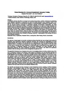
This scenario challenges the test and validation of the produced Software and the likelihood of a “recall” hang above us like a modern Sword of Damocles (see appendix). Typically, the test and validation of embedded software functions is done using a manual vehicle simulator where vehicle and engine parameters (e.g. engine speed, coolant temperature) are changed independently, by hand. This set-up can be illustrated in the figure 1 below.
The use of dynamic simulator with automatic test routines helps to approach these issues. Nevertheless, their high cost hinders its widespread use. This paper will describe a virtual vehicle simulator technique that can potentially expedite and greatly lower the cost of a considering part of the Software testing problem. As an abstraction model, this virtual simulator can be viewed as if it was a real, hardware based, dynamic simulator, allowing the communized test scripts and programmatic tools and interfaces.
INTRODUCTION The “Mythical Man-Month: Essays on Software Engineering” [1] is a book on software engineering and project management, whose central theme is that "adding manpower to a late software project makes it later". This idea is known as Brooks's law. The subject of this book is still a hot topic nowadays.
Figure 1: Software test setup using manual vehicle simulator The Conventional Testing using Manual Vehicle Simulators is very slow, limited and dependent on operator it is a bottleneck in the software development process; In order to expedite the testing/validation of software the manual simulators gave place to its modern version: a computer controlled simulator called dynamic simulator, See figure 2 below.
The increasing software complexity, the growing number of vehicle variants as well as the extensive diagnostic requirements and reduced number of test vehicles, require moving the calibration and test of embedded controls to test benches, HiL systems and virtual environments. [2] On top of that, the calibration efforts can be largely reduced by employing automation, numerical optimization and simulation methods. The amount of Software inside a vehicle is increasing very fast as long as the number of functions and intelligent controls are abundant.
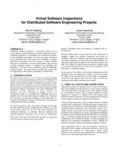
Figure 2: Dynamic Vehicle Simulator from PI Technologies Co. In this set-up, see figure 3 below, the engine and vehicle parameters are controlled programmatically opening many opportunities for testing and debugging of software, as the
dynamic simulator could reproduce real time behavior acquired from test vehicles.
the need to have competitive costs puts a limit on the engineering laboratory budget.
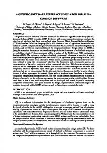
This set-up was instrumental in making the debug process as well as the validation/test easier , as the work of Zheng’s paper [3] [4] shows. See figure 4.
THE VIRTUAL SIMULATOR CONCEPT In the virtual simulator concept we separate the evaluation of sensor inputs and actuators drive from the use and computation of these values respectively.
Figure 3: Software test setup using dynamic vehicle simulator
We introduce a new layer between the application level and Hardware Abstraction Layer (HAL) called “Virtual Input/Output Layer” (VIOL). See figure 6 below.
The use of dynamic simulators not only improves the quality and velocity of testing but also enable for tests, those that were not possible to implement manually.
Figure 6: A Virtual Simulator Layer is added Between the Hardware Abstraction Layer and Application Interface
Figure 4: Comparison of execution and impossible test case manual execution vs. automated test [3] As in the case of the manual simulator the equipment generates a signal like the ECM was connected to real sensors, many times, the corresponding outputs of the ECM are connected to real actuators. The software is tested as a whole, as depicted in the figure 5 below.
The abstraction model of this layer is shown in the figure 7 below. This layer enables the injection of values for the evaluated sensor inputs to the application layer, which will not distinguish that value from the one that comes from a real sensor or simulator. The injection of values in the driver for the actuators is already a common practice in the automotive software and is known as “slew” actuator variables.
Figure 7: Internal representation of “virtual” i/o layer The injection/reading of parameters can be done in a number of communication channels: KW2000 like commands CAN Calibration commands, instrumentation (i.e. ETAS or ITS) and micro-controller debug ports. See figure 8.
Figure 5: testing the Software System as a whole All these benefits did not come without a price: the big cost of such simulators. This high cost hinders its widespread use as
In this model, there are “flags” that instructs the virtual i/o to use either the parameter that comes from the HAL or from the Virtual I/O.
As the micro-simulator is small and low cost, every engineer can have one at her desk. This physical accessibility is also important as this is known to reduce the time to go to the laboratory to wait for and use the available dynamic or manual simulators.
HARDWARE ABSTRACTION LAYER TESTING After the implementation of the Virtual I/O layer, the Hardware Abstraction Layer is tested using simple simulator and techniques. That is because it will be done just once for that version of HAL. Needless to say that the final Software testing, “level control”, is done using rigorous testing procedures. See figure 11 below. Figure 8: The DEComm driver can interface to different ECM channels and Computer Programs In order to keep the software simple the engine speed signal (and sometimes the CAM signal too) are injected physically. This signal can be a fixed frequency signal, as the value of actual engine speed will be injected by the Virtual I/O layer. See figure 9.
Using the block diagram of the functions layers the HAL test can be represented as in figure 11 below. Only the hardware and virtual I/O interfaces will be tested. After it is assured that this interface works correctly, the testing of application layer functions can be performed.
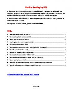
Figure 11: Testing of the Hardware Abstraction Layer Figure 9: Model for Software Functional Testing using the “Virtual” Simulator That way, the application layer can be tested using injected values and the corresponding actuator drive can be measured on the same way. The generation of engine speed signal is done using a microsimulator, see figure 10, that is connected to the ECM via a simplified connector energized using a simple wall power supply.
Figure 12: Testing of the Hardware Abstraction Layer
APPLICATION LAYER TESTING The application layer testing will only use injected values for the sensor signals, as depicted in the figure 13 below. The complexity of testing was divided as the hardware layer, together with some basic diagnostic is not performed. Figure 10: Micro-simulator and wall power supply
The software engineer can test a newly developed function right after the program is compiled and “flashed” in the ECM.
This concept, although simple, has the same reach and power as the dynamic simulators, not limiting the complexity of the tests involved. It’s important to highlight that only tests tightly connected to the hardware abstraction layer can be better tested using conventional, hardware based simulators.
Figure 13: Testing of the Application Layer The fact of the Virtual Simulator technique uses very limited hardware does not mean that it is limited. It can be done in a way that one can not distinguish for using this technique or a real “full blown” dynamic simulator costing hundreds of thousands of dollars.
Finally, the widespread use of dynamic simulators will allow for better software testing increasing the quality of embedded systems.
REFERENCES 1. 2.
The same interfaces can be used seamlessly, together with the same test scripts, see one example in the listing 1 below.
3.
Simulation of the behavior of actuators, which is being used nowadays using Hardware in the Loop techniques [5], can also be done. See figure 14.
4. 5.
6.
Brooks, F.; "The Mythical Man-Month ". AddisonWesley Press. ISBN.: 0-201-83595-9 (1995 ed.) Nelson, E. and Huang, H.; "A Software and System Modeling Facility for Vehicle Environment Interactions". ASWSD 2006. pp-34-47. Zheng, Q.; Chung, W.; Defore, K. and Herman, A.; "A Hardware-in-the-loop Test Bench for Production Transmission Controls". SAE paper 2007-01-0502. 2007 SAE World Congress. Detroit. USA. Habeebullah, A.; Zheng, Q. and Chung, W.; "A ClosedLoop Drive-train Model for HIL Test Bench". SAE paper 2009-01-1139. 2009 SAE World Congress. Detroit. USA. Chen, Y. and Carpenter, R.; "Use of Feedback Control to Improve HIL Based ECU System Function Testing". SAE paper 2010-01-0663. 2010 SAE World Congress. Detroit. USA. http://ancienthistory.about.com/od/basics101/g/SwordofD amocles.htm (accessed in 20th., May, 2011)
CONTACT INFORMATION
Listing 1 Example of test script
Figure 14: Enhanced testing mechanization by introducing feedback control [1]
SUMMARY/CONCLUSIONS It has been explained that the concept of the Virtual Vehicle Simulator has such a low cost that even low budgets programs could afford to put one on every engineer’s desk.
Orlando Volpato Filho. Electronics Advanced Engineering Supervisor. Delphi South America Technical Center. e_mail:
[email protected]
DEFINITIONS/ABBREVIATIONS ECM: Engine Control Module; TCM: Transmission Control Module; PCM: Powertrain Control Module; AutoBOB: Automated Break-Out-Box; HAL: Hardware Abstraction Layer; HWIO: Hardware Input Output Layer; HIL: Hardware in the Loop; SIL: Software in the Loop; VIOL: Virtual Input/Output Layer Matlab, Simulink, Stateflow, SimDriveline are Registered Trademarks of MathWorks, Inc. TestDrive is a Registered Trademark of Opal-RT Technologies. INCA is a Registered Trademark of ETAS Inc.
APPENDIX [6] Cicero tells the story of the Sword of Damocles in his Tusculan Disputations. The story is based on a legend about the Syracusan Dionysius II, which was a fourth century B.C. tyrant of Syracuse, a city in Magna Graecia, the Greek area of southern Italy. To all appearances Dionysius was very rich and comfortable, with all the luxuries money could buy, tasteful clothing and jewelry, and delectable food. He even had court flatterers (adsentatores) to inflate his ego. One of these ingratiators was the court sycophant, Damocles. Damocles used to make comments to the king about his wealth and luxurious life. One day when Damocles complimented the tyrant on his abundance and power, Dionysius turned to Damocles and said, "If you think I'm so lucky, how would you like to try out my life?" Damocles readily agreed, and so Dionysius ordered everything to be prepared for Damocles to experience what life as Dionysius was like. Damocles was enjoying himself immensely... until he noticed a sharp sword hovering over his head, that was suspended from the ceiling by a horse hair. This, the tyrant explained to Damocles, was what life as ruler was really like. Damocles, alarmed, quickly revised his idea of what made up a good life, and asked to be excused. He then eagerly returned to his poorer, but safer life.