The inability to oversee the printing process leads to late or omitted detection of failures. Rejects ..... We use OpenCV[17] in Version 3.0 and the Python API as this software provides ..... aachen.de/files/publications/2012/JAC12a.pdf (2012). 11.
MATEC Web of Conferences 59, 06003 (2016)
DOI: 10.1051/ matecconf/20165906003
IC FS T 2016
Vision based error detection for 3D printing processes Felix Baumann and Dieter Roller University of Stuttgart, IRIS, D-70569 Stuttgart, Germany
Abstract. 3D printers became more popular in the last decade, partly because of the expiration of key patents and the supply of affordable machines. The origin is located in rapid prototyping. With Additive Manufacturing (AM) it is possible to create physical objects from 3D model data by layer wise addition of material. Besides professional use for prototyping and low volume manufacturing they are becoming widespread amongst end users starting with the so called Maker Movement. The most prevalent type of consumer grade 3D printers is Fused Deposition Modelling (FDM, also Fused Filament Fabrication FFF). This work focuses on FDM machinery because of their widespread occurrence and large number of open problems like precision and failure. These 3D printers can fail to print objects at a statistical rate depending on the manufacturer and model of the printer. Failures can occur due to misalignment of the print-bed, the print-head, slippage of the motors, warping of the printed material, lack of adhesion or other reasons. The goal of this research is to provide an environment in which these failures can be detected automatically. Direct supervision is inhibited by the recommended placement of FDM printers in separate rooms away from the user due to ventilation issues. The inability to oversee the printing process leads to late or omitted detection of failures. Rejects effect material waste and wasted time thus lowering the utilization of printing resources. Our approach consists of a camera based error detection mechanism that provides a web based interface for remote supervision and early failure detection. Early failure detection can lead to reduced time spent on broken prints, less material wasted and in some cases salvaged objects.
1 Introduction Contemporary consumer grade 3D printers are often cube shaped with a size in the range of 50 cm edge length. This is due to the mechanics surrounding the build area that is on average 15x15x15 cm in size for consumer grade printers. With a weight of about 10 kg they could be placed on the desk of the user but are recommended to be placed away from the user due to potentially harmful fumes emitting during the printing process. Different technologies for 3D printing or additive manufacturing exist[1], ranging from metal-powder or ceramic[2] based laser sintering over laminated object modelling, resin based stereolitography to thermoplastics based fused deposition modelling (FDM). The most common class for consumer grade 3D printers is FDM. FDM printers are cheap to manufacture as they are mechanically simple and do not require complex and expensive components. Their makeup consists of 3 axes that are controlled by 3 stepper motors. These axis and motors are the main components, beside the print-head and print-bed and are affixed in a constellation that enables 3 degrees of freedom along these axes. This method offers reduced granularity of the objects compared to stereolitography. Applications are in rapid prototyping [3]. As it is recommended to utilize the printers in rooms different than the workplace of the user direct supervision
is inhibited. Printing errors [4],[5] occur for the following reasons: • Misalignment of the print-bed • Misalignment of the nozzle • Clogging of the nozzle • Depletion of printing material or disrupted material flow • Lack or loss of adhesion to the print-bed • Vibration or shock (from the printer or another source) As a goal misprints should be reduced because they consume material and occupy the printing device for long periods of time without producing a useful object. Printing times on FDM machines can range up to 20 hours for sufficiently complex and large objects. In order to alleviate the supervision problem users and manufacturers place video cameras (web cams) in or at the printer to facilitate remote supervision capabilities. Other error detection approaches facilitate laser scanners [6], [7], currents [8] or thermography[9]. This can help to receive information on potential problems and to assess the printing progress remotely but requires the user to watch the video stream either constantly or in intervals in order to get information on problems and errors. The goal is to support the user in detecting printing errors by utilizing machine vision [10]. The benefits are reduced material waste, reduced occupancy of printing resources due to early detection of print errors and the prevention of completion of the printing process for flawed or broken
© The Authors, published by EDP Sciences. This is an open access article distributed under the terms of the Creative Commons Attribution License 4.0 (http://creativecommons.org/licenses/by/4.0/).
MATEC Web of Conferences 59, 06003 (2016)
DOI: 10.1051/ matecconf/20165906003
IC FS T 2016
In our sketch the detachment is visible as the object has moved to the right and the original position is marked with dashed lines. The displacement between the original and the actual position is called the displacement error. In [12] this error type is described as a result of material warping. This error type/class can occur • When the temperature of the print-bed fluctuates and the object cools non-uniformly • When the print-bed is not adjusted and calibrated and therefore the distance between the nozzle and the printbed varies • Due to vibration or shock that detaches the object
objects and reduced time effort for the end user due to the alleviation of the need for constant supervision. For our approach we utilize consumer grade video cameras mounted before the 3D printer (Makerbot Replicator 2X [11]) and video analysis software. This work describes the design decisions and the underlying foundations for this system. This work is structured as follows: In this section the problem and motivate our approach is described by displaying the consequences of the problem. In section [2 Error Classes] we describe error classes present in this area and explain which we address with our approach. In the following section [3 Optical Error Detection] we describe our approach to visual error detection in FDM. Section [4 Results] displays the results from an experiment conducted to validate this approach. In section [5 Discussion] we discuss our approach from the software side and conclude with an outlook in [6 Conclusion and Future Work].
2.2 Missing material flow
2 Error classes In order to provide successful error detection it is important to define the errors to be encountered beforehand. We will lay out the errors that can arise and which classes we can detect with our approach. We define five error classes of which we can detect class one, two and three with our system. Classes four and five are not detected due to complexity of their detection. We propose these error classes as no systematical research on error classification in FDM is present.
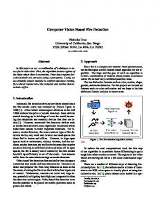
Figure 2. Missing material flow from the extruder nozzle.
With this error type the thermoplastic does not flow through the nozzle of the print head. The print head moves along its predetermined tool-path without extruding the filament. The height of the object stays constant and the object moves along the print-beds Z dimension downwards. The object is not complete and will not be completed. If the material flow is interrupted only temporarily the object will be printed defective as one or more layers of material are missing. If the material flow is interrupted only briefly the object might be printed completely with only minor defects as layers can compensate for missing lower layer parts to a small degree. In [13] this error is detected using acoustic emissions from the printer. In figure 2 this error type is depicted. The object is displayed as a striped rectangle with rounded corners, the print-bed is shown as the thick black line below the printing object and the print-head or extruder is displayed as the white rectangle with a striped pentagon below. The upper part of the sketch shows the case that the object is printed normally without errors and the extruder is adjacent to the object. The lower part shows the case where the material flow has stopped, the extruder does not touch the object anymore and moves along its tool-path. In the lower case an abort signal can be sent to the printer as this error is not recoverable. This class of error can occur due to • Clogged Nozzle/Extruder • Air-bubbles in the extruder • Jammed material (filament string is broken or extruder motor cannot grip the filament for transportation into the nozzle) • Depleted material
2.1 Detachment
Figure 1. Vertical movement due to detachment of object from printing-bed.
The most prevalent error and the easiest to detect is the detachment of the object from the print-bed. The object must not detach for the object to be printed successfully. In figure 1 this error is presented in two sketches. The striped rectangle with rounded corners represents the object to be printed and is attached to the print-bed (represented by the thick black bar below the object). In a print without errors this object is firmly attached to the print-bed and does not move in any direction relative to the print-bed. The printer in our approach has a print-bed that has one degree of freedom in the Z-direction (height) and a print-head with two degrees of freedom in X and Y direction (left/right and forward/backward). Other configurations of printers might need an adjustment because there the print-bed can move in two dimensions.
2.3 Deformed object
2
MATEC Web of Conferences 59, 06003 (2016)
DOI: 10.1051/ matecconf/20165906003
IC FS T 2016
error class is hard to detect automatically as no obvious defects occur. In order to detect these errors the object needs to be compared to the model. There is a problem in acquiring a 3D dimensional representation of the object while printing as rotational 3D Laser scanners are prohibitive due to the common design of 3D printers. Inferring 3D geometry through multi camera systems is possible but expensive due to the multitude of angles that need to be analysed for a complete 3D geometry suitable for comparison with the model. As models can be fine detailed a camera system with a high resolution is necessary, varying lighting situation and various coloured materials need to be taken into account.
As a further error class deformed objects that are not printed according to their CAD template is described. These errors can occur at areas with an overhang or at bridges as described in [14]. Overhangs and bridges are sections of the object where parts of the lower layer are intentionally missing. The printer extrudes material into the air spanning a path between two points with lower layer support (in case of a bridge) or over the edge of a lower layer supporting material (for overhangs). For bridging the printer tries to compensate by moving at higher speeds but sagging does usually occur for longer bridges as the material is drawn downwards due to gravity. When printing a filigree or unstable structure or when the printing parameters are chosen unsuitable regarding the supporting structures the object can topple over (With or without partial detachment from the printbed) or collapse. Following this the object is either pushed aside and around by the extruder if detached completely from the print-bed or the extruder cannot position itself at the correct position in order to complete the object due to missing layers and adhesion points. The object or parts of the objects can in this case become stuck to the extruder and be partially re-molten. The extruder keeps extruding material that forms a clot around the nozzle requiring extensive cleaning and or maintenance of the extruder. This error class has features from the error classes of missing material flow [2.2 Missing Material Flow] and loss of adhesion from the print-bed [2.1 Detachment] and therefore can be detected utilizing methods designed for them.
3 Optical error detection In order to detect errors from the error classes defined in [2.1 Detachment] to [2.3 Deformed Object] this work utilizes an auxiliary thresholding algorithm. With this algorithm we segment the digital image into binary images with a clear distinction between the object and the background. Our algorithm segments an image from a Playstation EyeCam camera with an OmniVision chip of the resolution of 640 pixels by 480 pixels into the object that is represented in white in the following images. We have chosen this specific camera as it provides a fixed focus and is broadly available at low cost. High cost system can be inhibitive for the utilization by users of such systems. The frame rate is set to 25 frames per second with the camera capable of providing up to 120 frames per second in reduced resolution.
2.4 Surface errors This error class is easily detectable for human users but very hard in a machine vision system. This class encompasses errors that manifest themselves in unclean, broken or in other ways deviating surfaces from the model. FDM printing has by design a problem with smooth surfaces and very sharp structures. In [15] the reasons and occurrences of this error class are discussed. Smooth surfaces are not possible as the material is deposited in rows by the extruder, either overlapping partially or with a gap. Sharp structures are not possible due to the thickness of the deposited material that can be regarded as string like. These errors stem from a mismatch between the chosen parameters for slicing and printing and the objects geometry. Printing fine structures with high speeds is error prone.
3.1 Camera position calibration
Figure 3. Visual marker positions.
Our system requires the geometry of the 3D printer and the relation to the position of the camera system to be known. We utilize optical markers (see fig. 3) to determine specific parts of the 3D printer and derive the layout from them. Circular markers are utilized to determine a horizontal ground line representing the printbed. The print-head is identified with a pair of circular markers horizontally aligned and the printing nozzle identified by the distance between the circular markers halved. With this information the video frame can be cropped to the area of interest in order to save computational effort.
2.5 Deviation from model This error is hard to detect automatically as the object is printed without any of the previously mentioned errors but differs from the model (i.e. template) e.g. in size or structure. In [16] this error class is discussed as appropriate test objects are discussed and proposed. The object does not exhibit obvious flaws and is printed successfully. This error class can occur when the user is using unsuitable parameters for slicing and printing. User actions like erroneous scaling or rotation can also lead to these errors. Errors due to shrinkage or warping when cooled can also lead to deviations from the model. This
3.2 Thresholding To segment the image into object (foreground) and background we utilize a thresholding algorithm with a threshold determined by the colour of the filament. We
3
MATEC Web of Conferences 59, 06003 (2016)
DOI: 10.1051/ matecconf/20165906003
IC FS T 2016
the algorithm determines the print-bed upper surface by finding associated parallel lines (CV CannyEdge Method) in a defined distance to a virtual line between the visual markers for the print bed. The nozzle tips are inferred from a known dimensional relationship between the visual markers and the nozzle tip. The pre-processing is composed of the following steps: • Detect Visual Markers • Determine Area of Interest and crop to it • Detect print-bed Upper Surface • Detect print-head Nozzle Tip In Figure 4 the relationship between the markers is shown with two false positive circle detections (Circle at right-hand bottom side, and circle at the top of the print object which is limited with a yellow line).
question the user for a marking of the object that is printed in the video frame. The user selects the colour with a mouse click from the video frame. We utilize a HSV (Hue-Saturation-Value) colour model for the selection as the native RGB (Red-Green-Blue) colour model is unsuitable for the stable detection of the object due to lighting changes and shadows on the object. Our system also supports a thresholding colour selection with sliders for a HSV combination in case the material stays constant for consecutive prints. 3.3 Utilized Software We use OpenCV[17] in Version 3.0 and the Python API as this software provides recent algorithms for image detection, manipulation and recognition. We use the packages GUI Features, Core Operations, Imaging Processing and Video Analysis. 3.4 Algorithm Our Algorithm is composed of the following steps: 1. Selection of thresholding Value via In-Picture Colour selection or HSV Combination selection via sliders 2. Conversion of original RGB video frame to HSV 3. Detection of visual markers for image cropping i.e. reduction to the area of interest (Pre-Processing [3.4.1 Pre-Processing]) 4. Thresholding of image to binary image with the selected threshold value 5. Blob detection and marking of candidate object 6. GOTO Step 2 Step 1 is performed by the user's interaction and ensures the appropriate thresholding value for further image analysis. We convert the original 640x480 pixel RGB image into HSV for easier selection of areas with the same colour, this alleviates problems due to changing lighting situations or shadows occurring on the object. Our system utilizes two different methods to detect movement of the object, differential [see 3.4.2 Differential Images] imaging and blob detection [see 3.4.3 Blob Detection]. The threshold parameters are user selected for every printed object and therefore not subjective to algorithmic selection.
Figure 4. (top) Visual markers and control points (bottom) cropped area of interest.
3.4.2 Differential images Subtraction of two consecutive images (i.e. video frames) yield a differential image. The differential image fdiff displays the temporal differences between two frames f 1 and f2: fdiff(x, y) = f1(x, y) – f2(x, y). More than two consecutive frames can be used to calculate differential images leading to movement detectable over longer periods of time. Our approach calculates fdiff from 3 consecutive images (ft-1, ft, ft+1 where t indicates a time stamp). We utilize 25 frames per second so this differential image spans a period of t=3/25 seconds. Stationary objects (i.e. background) are removed from the image frame. Only moving objects and picture errors remain as the content of the image. On an error free print the object does not change its horizontal location but will only grow vertically. A summation of pixels indicating horizontal change is an indicator for rapid horizontal movement i.e. detachment of the object from the print-bed. We integrate 3 consecutive frames for detection for a short response time to detachment detection. This approach is error prone as pixel errors from the camera can occur and also the area of the print-head needs to be cropped out precisely. Unstable objects that bend while printing are also prohibitive for this approach.
3.4.1 Pre-processing For pre-processing the image is examined and the area of interest is determined by analysing a set of visual markers. We investigate deriving the positions of the print-bed and print head with an algorithm for line and edge detection but find this to be too noisy due to colour grading of the parts to be detected and the large number of parallel lines in the design of our printer. Visual markers (see fig. 4) are used to indicate the significant parts of the print-head and print-bed which are identified by our algorithm. We utilize CV HoughCircles[18] to detect circular shapes in the image and reduce the number of possible false-positives by averaging the circle position over a 100 frame period and discard circles that are not in a defined dimensional relationship with each other[19]. With the visual markers identified and the image cropped to the area of interest
4
MATEC Web of Conferences 59, 06003 (2016)
DOI: 10.1051/ matecconf/20165906003
IC FS T 2016
3.4.3 Blob detection Areas with constant features (i.e. same colour, see fig. 5) in a digital image are called blobs. Our algorithm searches for blobs (see fig. 6) with the colour selected by the user as described in [3.2 Thresholding]. Multiple blobs can be detected in the image and the largest blob is selected as the candidate for the object. The algorithm tries to repair missing links between connected blobs in order to completely describe the object. After the candidate object is identified our algorithm describes the object with an enclosing bounding box. The centre of the bounding box is tracked in consecutive video frames for movement detection. As the object grows during the printing process, the bounding box and the centre of the bounding box is updated consequently. A small tolerance for object and centre detection is implemented as the object blob is not detectable completely congruent over time. If our algorithm detects a deviation of the centre of the detected object blob larger than the hard coded threshold this is indicative for a sudden movement of the object. If the object is detected to be not moving in the following frames only a warning to the user is issued. This can be due to pixel errors or mis-detection of the object block. Consecutive larger changes of the detected centre will trigger an error to the user or send the abort signal to the printer as per configuration.
Figure 7. Missing filament detection with nozzle reference line and object bounding box.
Figure 8. Blue object marked with bounding box.
Our test system has a height fixed print-head and is only moving in 2 dimensions (X and Y). We position the camera frontal to the print-head so that changes in the Y direction do not alter the apparent height in the video frame. When the camera is position at an angle to the print-head, the apparent height can change and this needs to be tracked utilizing the visual markers on the printhead. In the error free case the objects upper reference line and the print-head reference line are congruent. If the material flow stops the object moves down along the Z Axis with the print-bed and the print-head continues its operation. The object upper reference line and the printhead reference line diverge. We compare these reference lines in consecutive frames and issue a warning when the difference between them grows between a defined threshold ThreshFlow1. In case the difference continues to grow over a second Threshold ThreshFlow2 we issue an error to the user and abort the print as per configuration.
Figure 5. Extracted blob from blue object on printing-bed.
4 Results For validation of our approach we devise a test with two different test objects. Test object A (see fig. 9) is a block of 39x20x5 mm printed on a stand of 1x25x10 mm. It is printed in order to detect missing material flow when supply of filament is cut during print. Test object B (see fig. 10) is a triangular block for detection of deformed object failures and detachment. The standing area is chosen to be very small so that the object can topple over during print. Both test objects are printed 10 times each and the detection of the failures is observed with the interface. Test run A with test object A is executed with 5 objects printed without cutting the filament flow in order to ensure that no false positive detection occurs and with 5 objects printed with the filament flow cut off mid-print in order to ensure positive recognition of the failure detection.
Figure 6. Blue object on printing-bed.
3.4.4 Algorithm for missing material flow detection For the detection of missing material flow from the extruder the algorithm for the blob detection [see 3.4.3 Blob Detection] is used and extended (see fig. 7). The upper border of the object bounding box is used as a reference line. This object reference line is compared to the reference line for the print-head lower boundary (i.e. nozzle tip, see fig. 8) calculated by the image preprocessor [3.4.1 Pre-Processing].
5
MATEC Web of Conferences 59, 06003 (2016)
DOI: 10.1051/ matecconf/20165906003
IC FS T 2016
5 Discussion One obstacle in stable in stable error detection in our approach is pixel errors from the camera that can be compensated for by software interpolation and smoothing of the original video frame or to some extend with higher quality video cameras. Smoothing out the image feed consumes additional computational resources. Our system is capable of analysing a video stream with a resolution of 640x480 pixel and a framerate of 25 frames per second with an CPU utilization rate of about 20 percent on an Intel Pentium M 1.5 GHz computer. For display in the web interface the Portable Network Graphics (PNG) format is chosen for compatibility reasons. When this interface is optimized for a specific browser more efficient display methods for example WEBM can be implemented, this will increase the refresh rate of the displayed stream in the web interface which is approximately five seconds with the current setup. The second obstacle is change in lighting for the object. This can be alleviated by a fixed lighting system for the 3d printer. This fixed lighting system is set to be placed at multiple angles in front of by the side of the 3D printer in order to avoid the casting of shadows. One difficulty we have encountered with additional lighting is that reflections can destabilize our algorithm as some surfaces of the 3D printer are highly reflective. Increasing the video resolution and framerate can yield better images suitable for detection of errors currently not detectable as surface problems. This will also increase the computational effort. For our test system an increase of resolution and framerate was found to be not necessary as the error classes we want to detect are detected with a high degree of certainty. Our approach is not suited for flat objects because of the camera position. It is also not suitable for materials that are of similar colour as the 3D printer as the difference in colour is needed for the thresholding and identification of the object. Strategies on how to handle detected failures (e.g. issue abort command to printer) and when to handle detected failures (in order to prevent action on false positives) are to be devised and are dependent upon the scenario the printer is operated in. Those strategies can be implemented in our prototype as external scripts. With adaptions our prototype can be used in scenarios for cloud based manufacturing where remote supervision is to be provided to the users.
Figure 9. Test Object A.
Figure 10. Test Object B.
Test run B with test object B is executed 10 times undisturbed with the object toppling over randomly 6 times. In test run A the undisturbed prints yield a number of warnings during the print due to temporary detection problems and one mis-detected print failure. This results in a false detection rate of one out of five (20% false positive for material flow detection). Test objects with cut-off filament are detected earliest with an update to the displayed frame (ca. 5 seconds) and one print not detected as failure to do mis-detection of the extruder position. This results in four out of five objects correctly classified as failed (80% detection rate for material flow failures). For test run B six objects (see fig. 11) out of ten toppled over. Four objects are correctly classified as failed resulting in 60% detection rate for object detachment. The remaining prints again are classified with a number of warnings and two objects are temporarily marked as failed. The temporary failures detected are corrected within a time span of 30 to 90 seconds. Lighting changes can be identified as a source of increased detection errors. For detachment detection the detection rate is 60% in our experiment. The algorithm implemented is reasonably stable but is to be improved for resilience against lighting changes, marker misdetection.
6 Conclusion and future work With this work we propose an algorithmic implementation of error detection based on video camera data for FDM 3D printers. From the five classes of proposed error classification we are able to detect three. We show the validity of our approach by an experiment that shows the algorithm is capable of a 60 to 80 percent detection rate for failure detection with a false positive detection rate of 60 to 80 percent. Improvements described in [5 Discussion] are expected to bring the rate of false positives down and the detection rate up. For future work the implementation of additional error
Figure 11. Test object b during print with offset extruder detection line.
6
MATEC Web of Conferences 59, 06003 (2016)
DOI: 10.1051/ matecconf/20165906003
IC FS T 2016
8.
detection algorithms and stabilization and improvement of implemented algorithms is advised. In following prototypes the interface and algorithms are to be implemented in an integrated interface for cloud based manufacturing. For future research we suggest implementing and extending our basic approach into multi camera systems and stereo vision camera systems. This will improve the object detection capability as there is better understanding for the scene geometry and therefore for object detection in the depth dimension. Furthermore we suggest looking into IR cameras for this setup as this can reduce glaring effects and reflection with appropriate lighting.
9.
10.
Acknowledgement
11.
We would like to thank Daniel Nägele, Lan Jiang and Robert Gänzle for their work in this project.
12.
References 1.
2.
3.
4.
5.
6.
7.
F. Klocke and W. König, Fertigungsverfahren 3: Abtragen, Generieren und Lasermaterialbearbeitung, Springer, ISBN 9783540489542 (2007) T. Fang, M. A. Jafari, S. C. Danforth, A. Safari, Signature analysis and defect detection in layered manufacturing of ceramic sensors and actuators, Machine Vision and Applications, Vol. 15 Iss. 2, DOI: 10.1007/s00138-002-0074-1 (2013) T. Pham and S. S. A. Dimov, Rapid Manufacturing: The Technologies and Applications of Rapid Prototyping and Rapid Tooling, Springer, ISBN 9781852333607 (2001) C. Bayley, L. Bochmann, C. Hurlbut, M. Helu, R. Transchel and D. Dornfeld, Understanding Error Generation in Fused Deposition Modeling, SPRING TOPICAL MEETING Vol. 57 pp. 98-103 (2014) R. Anitha, S. Arunachalam and P. Radhakrishnan, Critical parameters influencing the quality of prototypes in fused deposition modelling, Journal of Materials Processing Technology Vol. 118 pp. 385388 (2001) T. Craeghs, F. Bechmann, S. Berumen, J.-P. Kruth, Feedback control of Layerwise Laser Melting using optical sensors, Physics Procedia Vol. 5 Part B, pp. 505–514, DOI: 10.1016/j.phpro.2010.08.078 (2010) J. J. Ballyns, D. L. Cohen, E. Malone, S. A. Maher, H. G. Potter, T. Wright, H. Lipson and L. J. Bonassar, An Optical Method for Evaluation of Geometric Fidelity for Anatomically Shaped Tissue-Engineered Constructs, TISSUE ENGINEERING: Part C Vol. 16 No. 4 pp. 693-703, DOI: 10.1089/ten.tec.2009.0441. (2010)
13.
14.
15.
16.
17.
18.
19.
7
C. Kim, D. Espalin, A. Cuaron, M. A. Perez, E. MacDonald and R. B. Wicker, A Study to Detect a Material Deposition Status in Fused Deposition Modeling Technology, IEEE Int. Conf. On Adv. Int. Mechatronics AIM, pp. 779-783 (2015) H. Krauss, T. Zeugner and M. F. Zaeh, Layerwise Monitoring of the Selective Laser Melting Process by Thermography, Physics Procedia, Vol. 56, pp. 64-71, DOI: 10.1016/j.phpro.2014.08.097 (2014) S. Kleszczynski, J. zur Jacobsmühlen, J. T. Sehrt and G. Witt, ERROR DETECTION IN LASER BEAM MELTING SYSTEMS BY HIGH RESOLUTION IMAGING, Proceedings of the Solid Freeform Fabrication Symposium, URL: http://www.lfb.rwthaachen.de/files/publications/2012/JAC12a.pdf (2012) B. Pettis, A. K. France and J. Shergill, Getting Started with MakerBot, Published by O'Reilly, ISBN 9781449338657 (2013) T.-M. Wang, J.-T. Xi and Y. Jin, A model research for prototype warp deformation in the FDM process, The International Journal of Advanced Manufacturing Technology, Vol. 33, Iss. 11, pp. 1087-1096 (2007), DOI: 10.1007/s00170-006-05569 H. Wu, Y. Wang and Z. Yu, In situ monitoring of FDM machine condition via acoustic emission, International Journal of Advanced Manufacturing Technology, pp. 1-13 (2015), DOI: 10.1007/s00170015-7809-4 N. Volpato, J. A. Foggiatto, D. C. Schwarz, The influence of support base on FDM accuracy in Z, Rapid Prototyping Journal, Vol. 20 Iss 3 pp. 182191, (2014), DOI: 10.1108/RPJ-12-2012-0116 P. Chennakesava and Y. S. Narayan, Fused Deposition Modeling - Insights, International Conference on Advances in Design and Manufacturing (ICAD&M'14), ISBN 978-93-8474312-3, (2014) S. P. Moylan, J. A. Slotwinski, A. L. Cooke, K. K. Jurrens and M. A. Donmez, Proposal for a standardized test artifact for additive manufacturing machines and processes, Proceedings of the 23rd International Solid Free Form Symposium - An Additive Manufacturing Conference, pp. 902-920, (2012) G. Bradski and A. Kaehler, Learning OpenCV: Computer Vision with the OpenCV Library, O'Reilly Media, ISBN 9780596554040 (2008) H. K. Yuen, J. Princen, J. Illingworth and J. Kittler, Comparative study of Hough transform methods for circle finding, Image and Vision Computing Vol. 8 pp. 71-77 (1990) B. Jähne, Digitale Bildverarbeitung, Springer, ISBN 9783540249993 (2005)