The cameras then undergo a common motion, described by a Euclidean ma- trix. M = [ R âR t. 0. 1. ] ... dently, then decompose them into rotation and translation.
Visual Odometry for Non-Overlapping Views Using Second-Order Cone Programming Jae-Hak Kim1 , Richard Hartley1 , Jan-Michael Frahm2 and Marc Pollefeys2 1
Research School of Information Sciences and Engineering The Australian National University. 1
National ICT Australia (NICTA)
?
2 Department of Computer Science University of North Carolina at Chapel Hill.
Abstract. We present a solution for motion estimation for a set of cameras which are firmly mounted on a head unit and do not have overlapping views in each image. This problem relates to ego-motion estimation of multiple cameras, or visual odometry. We reduce motion estimation to solving a triangulation problem, which finds a point in space from multiple views. The optimal solution of the triangulation problem in Linfinity norm is found using SOCP (Second-Order Cone Programming) Consequently, with the help of the optimal solution for the triangulation, we can solve visual odometry by using SOCP as well.
1
Introduction
Motion estimation of cameras or pose estimation, mostly in the case of having overlapping points or tracks between views, has been studied in computer vision research for many years [1]. However, non-overlapping or slightly overlapping camera systems have not been studied so much, particulary the motion estimation problem. The non-overlapping views mean that all images captured with cameras do not have any, or at most have only a few common points. There are potential applications for this camera system. For instance, we construct a cluster of multiple cameras which are firmly installed on a base unit such as a vehicle, and the cameras are positioned to look at different view directions. A panoramic or omnidirectional image can be obtained from images captured with a set of cameras with small overlap. Another example is a vehicle with cameras mounted on it to provide driving assistance such as side/rear view cameras. An important problem is visual odometry – how can we estimate the tracks of a vehicle and use this data to determine where the vehicle is placed. There has been prior research considering a set of many cameras moving together as one camera. In [2] an algebraic solution to the multiple camera motion problem is presented. Similar research on planetary rover operations has been conducted to ?
NICTA is funded by the Australian Government’s Backing Australia’s Ability initiative, in part through the Australian Research Council.
estimate the motion of a rover on Mars and to keep track of the rover [3]. Other research on visual odometry has been performed to estimate the motion of a stereo rig or single camera [4]. Prior work on non-overlapping cameras includes most notably the paper [5]. This differs from our work in aligning independently computed tracks of the different cameras, whereas we compute a motion estimate using all the cameras at once. Finally, an earlier solution to the problem was proposed in unpublished work of [6], which may appear elsewhere. In this paper, we propose a solution to estimate the six degrees of freedom (DOFs) of the motion, three rotation parameters and three translation parameters (including scale), for a set of multiple cameras with non-overlapping views, based on L∞ triangulation. A main contribution of this paper is that we provided a well-founded geometric solution to the motion estimation in non-overlapping multiple cameras.
2
Problem formulation
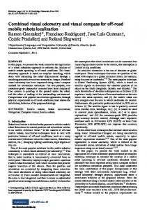
Consider a set of n calibrated cameras with non-overlapping fields of view. Since the cameras are calibrated, we may assume that they are all oriented in the same way just to simplify the mathematics. This is easily done by multiplying an inverse of the rotation matrix to the original image coordinates. This being the case, we can also assume that they all have camera matrices originally equal to Pi = [I| − ci ]. We assume that all ci are known. The cameras then undergo a common motion, described by a Euclidean matrix � � R −R t (1) M= 0> 1 where R is a rotation, and t is a translation of a set of cameras. Then, the i-th camera matrix changes to � > � R t P0i = Pi M−1 = [I | − ci ] > = [R> | t − ci ] 0 1 which is located at R(ci − t). Suppose that we compute all the essential matrices of the cameras independently, then decompose them into rotation and translation. We observe that the rotations computed from all the essential matrices are the same. This is true only because all the cameras have the same orientation. We can average them to get an overall estimate of rotation. Then, we would like to compute the translation. As we will demonstrate, this is a triangulation problem. Geometric concept. First, let us look at a geometric idea derived from this problem. An illustration of a motion of a set of cameras is shown in Figure 1. A bundle of cameras is moved by a rotation R and translation t. All cameras at ci are moved to c0i . The first camera at position c01 is a sum of vectors ci , c0i − ci and c01 − c0i where i = 1...3. Observing that the vector vi in Figure 1
R, t c03
c02
c3 c2 c1
v1 c01
v2 c2 + R(c1 − c2) v3 c3 + R(c1 − c3)
Fig. 1. A set of cameras is moved by Euclidean motion of rotation R and translation t. The centre of the first camera c1 is moved to c01 by the motion. The centre c01 is a common point where all translation direction vectors meet. The translation direction vectors are indicated as red, green and blue solid arrows which are v1 , v2 and v3 , respectively. Consequently, this is a triangulation problem.
is the same as the vector c0i − ci and the vector c01 − c0i is obtained by rotating the vector c1 − ci , the first camera at position c01 can be rewritten as a sum of three vectors ci , R(c1 − ci ) and vi . Therefore, the three vectors vi , colored solid arrows in Figure 1 meet in one common point c01 , the position of the centre of the first camera after the motion. It means that finding the motion of the set of cameras is the same as solving a triangulation problem for translation direction vectors derived from each view. Secondly, let us derive detailed equations on this problem from the geometric concept we have described above. Let Ei be the essential matrix for the i-th camera. From E1 , we can compute the translation vector of the first camera, P1 , in the usual way. This is a vector passing through the original position of the first camera. The final position of this camera must lie along this vector. Next, we use Ei , for i > 1 to estimate a vector along which the final position of the first camera can be found. Thus, for instance, we use E2 to find the final position of P1 . This works as follows. The i-th essential matrix Ei decomposes into Ri = R and a translation vector vi . In other words, Ei = R[vi ]× . This means that the i-th camera moves to a point ci + λi vi , the value of λi being unknown. This point is the final position of each camera c0i in Figure 1. We transfer this motion to determine the motion of the first camera. We consider the motion as taking place in two stages, first rotation, then translation. First the camera centre c1 is rotated by R about point ci to point ci + R(c1 − ci ). Then it is translated in the direction vi to the point c01 = ci + R(c1 − ci ) + λi vi . Thus, we see that c01 lies on the line with direction vector vi , based at point ci + R(c1 + ci ).
In short, each essential matrix Ei constrains the final position of the first camera to lie along a line. These lines are not all the same, in fact unless R = I, they are all different. The problem now comes down to finding the values of λi and c01 such that for all i: c01 = ci + R(c1 − ci ) + λi vi
for i = 1, ..., n .
(2)
Having found c01 , we can get t from the equation c01 = R(c1 − t). Averaging Rotations. From the several cameras and their essential matrices Ei , we have several estimates Ri = R for the rotation of the camera rig. We determine the best estimate of R by averaging these rotations. This is done by representing each rotation Ri as a unit quaternion, computing the average of the quaternions and renormalizing to unit norm. Since a quaternion and its negative both represent the same rotation, it is important to choose consistently signed quaternions to represent the separate rotations Ri . Algebraic derivations. Alternatively, it is possible to show an algebraic derivation of the equations as follows. Given Pi = [I| − ci ] and P0i = [R> | t − ci ] ( See (2)), an essential matrix is written as Ei = R> [ci + R(t − ci )]× I = [R> ci + (t − ci )]× R> .
(3)
Considering that the decomposition of the essential matrix Ei is Ei = Ri [vi ]× = [Ri vi ]× Ri , we may get the rotation and translation from (3), namely Ri = R> and λi Ri vi = R> ci + (t − ci ). As a result, t = λi R> vi + ci − R> ci which is the same equation derived from the geometric concept. A Triangulation Problem. Equation (2) gives us independent measurements of the position of point c01 . Denoting ci + R(c1 − ci ) by Ci , the point c01 must lie at the intersection of the lines Ci + λi vi . In the presence of noise, these lines will not meet, so we need find a good approximation to c01 . Note that the points Ci and vectors vi are known, having been computed from the known calibration of the camera geometry, and the computed essential matrices Ei . The problem of estimating the best c01 is identical with the triangulation problem studied (among many places) in [7, 8]. We adopt the approach of [7] of solving this under L∞ norm. The derived solution is the point c01 that minimizes the maximum difference between c01 − Ci and the direction vector vi , for all i. In the presence of noise, the point c01 will lie in the intersection of cones based at the vertex Ci , and with axis defined by the direction vectors vi . To formulate the triangulation problem, instead of c01 , we write X as the final position of the first camera where all translations derived from each essential matrix meet together. As we have explained in the previous section, in the presence of noise we have n cones, each one aligned with one of the translation directions. The desired point X lies in the overlap of all these cones, and, finding this overlap region gives the solution we need in order to get the motion
of cameras. Then, our original motion estimation problem is formulated as the following minimization problem: min max X
i
||(X − Ci ) × vi || . (X − Ci )> vi
(4)
Note that the quotient is equal to tan2 (θi ) where θi is the angle between vi and (X − Ci ). This problem can be solved as a Second-Order Cone Programming (SOCP) using a bisection algorithm [9].
3
Algorithm
The algorithm to estimate motion of cameras having non-overlapping views is as follows: Given: 1. A set of cameras described in initial position by their known calibrated camera matrices Pi = Ri [I| − ci ]. The cameras then move to a second (unknown) position, described by camera matrices P0i . 2. For each camera pair Pi , P0i , several point correspondences xij ↔ x0ij (expressed in calibrated coordinates as homogeneous 3-vectors). Objective: Find the motion matrix of the form (1) that determines the common motion of the cameras, such that P0i = Pi M−1 . Algorithm: 1. Normalize the image coordinates to calibrated image coordinates by setting 0 ˆ ij = R−1 ˆ 0ij = R−1 x i xij and x i xij ,
2. 3. 4. 5.
ˆ ij ← x ˆ ij /kˆ ˆ 0ij ← x ˆ 0ij /kˆ then adjust to unit length by setting x xij k and x x0ij k. 0 ˆ ij ↔ x ˆ ij for Compute each essential matrix Ei in terms of correspondences x the i-th camera. Decompose each Ei as Ei = Ri [vi ]× and find the rotation R as the average of the rotations Ri . Set Ci = ci + R(c1 − ci ). Solve the triangulation problem by finding the point X = c01 that (approximately because of noise) satisfies the condition X = Ci + λi vi for all i. Compute t from t = c1 − R> c01 .
In our current implementation, we have used the L∞ norm to solve the triangulation problem. Other methods of solving the triangulation problem may be used, for instance the optimal L2 triangulation method given in [8]. Critical Motion. The algorithm has a critical condition when the rotation is zero. If this is so then, in the triangulation problem solved in this algorithm all the basepoints Ci involved are the same. Thus, we encounter a triangulation problem with a zero baseline. In this case, the magnitude of the translation can not be accurately determined.
4
Experiments
We have used SeDuMi and Yalmip toolbox for optimization of SOCP problems [10, 11]. We used a five point solver to estimate the essential matrices [12, 13]. We select the best five points from images using RANSAC to obtain an essential matrix, and then we improve the essential matrix by non-linear optimization. An alternative method for computing the essential matrix based on [14] was tried. This method gives the optimal essential matrix in L∞ norm. A comparison of the results for these two methods for computing Ei is given in Fig 6. Real data. We used Point Grey’s LadybugTM camera to generate some test data for our problem . This camera unit consists of six 1024×768 CCD color sensors with small overlap of their field of view. The six cameras, 6 sensors with 2.5mm lenses, are closely packed on a head unit. Five CCDs are positioned in a horizontal ring around the head unit to capture side-view images, and one is located on the top of the head unit to take top-view images. Calibration information provided by Point Grey [15] is used to get intrinsic and relative extrinsic parameters of all six cameras. A piece of paper is positioned on the ground, and the camera is placed on the paper. Some books and objects are randomly located around the camera. The camera is moved manually while the positions of the camera at some points are marked on the paper as edges of the camera head unit. These marked edges on the paper are used to get the ground truth of relative motion of the camera for this experiment. The experimental setup is shown in Figure 2. A panoramic image stitched in our experimental setup is shown in Figure 3. In the experiment, 139 frames of image are captured by each camera. Feature tracking is performed on the image sequence by the KLT (Kanade-Lucas-Tomasi) tracker [16]. Since there is lens distortion in the captured image, we correct the image coordinates of the feature tracks using lens distortion parameters provided by the Ladybug SDK library. The corrected image coordinates are used in all the equations we have derived. After that, we remove outliers from the feature tracks by the RANSAC (Random Sample Consensus) algorithm with a model of epipolar geometry in two view and trifocal tensors in three view [17]. There are key frames where we marked the positions of the camera. They are frames 0, 30, 57, 80, 110 and 138 in this experiment. The estimated path of the cameras over the frames is shown in Figure 4. After frame 80, the essential matrix result was badly estimated and subsequent estimation results were erroneous. A summary of the experimental results is shown in Tables 1 and 2. As can be seen, we have acquired a good estimation of rotations from frame 0 up to frame 80, within about one degree of accuracy. Adequate estimation of translations is reached up to frame 57 within less than 0.5 degrees. We have successfully tracked the motion of the camera through 57 frames. Somewhere between frame 57 and frame 80 an error occurred that invalidated the computation of the position of frame 80. Analysis indicates that this was due to a critical motion (near-zero rotation of the camera fixture) that made the translation estimation inaccurate. Therefore, we have shown the frame-to-frame rotations, over frames in Figure
Fig. 2. An experimental setup of the LadybugTM camera on an A3 size paper surrounded by books. The camera is moved on the paper by hand, and the position of the camera at certain key frames is marked on the paper to provide the ground truth for the experiments. Rotation pair (R0 , R1 ) (R0 , R2 ) (R0 , R3 )
True rotation Estimated rotation Axis Angle Axis [0 0 -1] 85.5◦ [-0.008647 -0.015547 0.999842] [0 0 -1] 157.0◦ [-0.022212 -0.008558 0.999717] [0 0 -1] 134.0◦ [ 0.024939 -0.005637 -0.999673]
Angle 85.15◦ 156.18◦ 134.95◦
Table 1. Experimental results of rotations at key frames 0, 30, 57 and 80, which correspond to the position number 0–3, respectively. For instance, a pair of rotation (R0 , R1 ) corresponds to a pair of rotations at key frame 0 and 30. Angles of each rotation are represented by the axis-angle rotation representation.
5-(a). As can be seen, there are frames for which the camera motion was less than 5 degrees. This occurred for frames 57 to 62, 67 to 72 and 72 to 77. In Figure 5-(c), we have shown the difference between the ground truth and estimated position of the cameras in this experiment. As can be seen, the position of the cameras is accurately estimated up to 57 frames. However, the track went off at frame 80. A beneficial feature of our method is that we can avoid such bad condition for the estimation by looking at the angles between frames and residual errors on the SOCP, and then we try to use other frames for the estimation. Using the L∞ optimal E-matrix. The results so-far were achieved using the 5-point algorithm (with iterative refinement) for calculating the essential matrix. We also tried using the method given in [14]. Since this method is quite new, we did not have time to obtain complete results. However, Fig 6 compares the
Fig. 3. A panoramic image is obtained by stitching together all six images from the LadybugTM camera. This image is created by LadybugPro, the software provided by Point Grey Research Inc.
0.1
0.08
0.06
0.04
0.03 0.025
0.02
0.02 0.015
0
0.01 0.005
−0.02
0 0.02
0
−0.02
−0.04
−0.06
−0.08
−0.1
−0.12
−0.14
−0.005 −0.14
(a) Top view
−0.12
−0.1
−0.08
−0.06
−0.04
−0.02
0
0.02
(b) Front view
Fig. 4. Estimated path of the LadybugTM camera viewed from (a) top and (b) front. The cameras numbered 0, 1, 2, 3, 4 and 5 are indicated as red, green, blue, cyan, magenta and black paths respectively.
angular error in the direction of the translation direction for the two methods. As may be seen, the L∞ -optimal method seems to work substantially better.
5
Discussion
We have presented a solution to find the motion of cameras that are rigidly mounted and have minimally overlapping fields of view. This method works equally well for any number of cameras, not just two, and will therefore provide more accurate estimates than methods involving only pairs of cameras. The method requires a non-zero frame-to-frame rotation. Probably because of this, the estimation of motion through a long image sequence significantly went off track.
Translation Scale ratio Angles pair True value Estimated value True value Estimated value (t01 , t02 ) 0.6757 0.7424 28.5◦ 28.04◦ ◦ (t01 , t03 ) 0.4386 1.3406 42.5 84.01◦ Table 2. Experimental results of translation between two key frames are shown in scale ratio of two translation vectors and in angles of that at the two key frames. The translation direction vector t0i is a vector from the centre of the camera at the starting position, frame number 0, to the centre of the camera at the position number i. For example, t01 is a vector from the centre of the camera at frame 0 to the centre of the camera at frame 30.
80 70 60
frame 30 frame 30
frame 0
50 60
frame 57 frame 57
40 420 −2 −4 −6 −8
30
40 20
frame 80
0
0
20 50
10 0 0
−20 100
50
100
150
frame 80 150
−40 −60
Fig. 5. The angles between pairs of frames used to estimate the motion are shown in (a). Note that a zero or near-zero rotation means a critical condition for estimating the motion of the cameras from the given frames. (b) Ground truth of positions (indicated as red lines) of the cameras with orientations at key frames 0, 30, 57 and 80, and estimated positions (indicated as black lines) of the cameras with their orientations at the same key frames. Orientations of the cameras are marked as blue arrows. Green lines are the estimated path through all 80 frames.
The method geometrically showed good estimation results in experiments with real world data. However, the accumulated errors in processing long sequences of images made the system produce bad estimations over long tracks. In the real experiments, we have found that a robust and accurate essential matrix estimation is a critical requirement to obtain correct motion estimation in this problem.
References 1. Hartley, R.I., Zisserman, A.: Multiple View Geometry in Computer Vision. Second edn. Cambridge University Press, ISBN: 0521540518 (2004) 2. Pless, R.: Using many cameras as one. In: CVPR03. (2003) II: 587–593 3. Cheng, Y., Maimone, M., Matthies, L.: Visual odometry on the mars exploration rovers. In: Systems, Man and Cybernetics, 2005 IEEE International Conference on. (2005)
Error of the estimation
Error of the estimation 30
Difference between the estimated translation direction and the translation from an essential matrix in degree
Difference between the estimated translation direction and the translation from an essential matrix in degree
30
25
20
15
10
5
0
0
20
40
60 Frames
80
(a) optimal
100
120
25
20
15
10
5
0
0
20
40
60
80
100
120
140
Frames
(b) 5-point
Fig. 6. Comparison of the angular error in the translation direction for two different methods of computing the essential matrix.
4. Nister, D., Naroditsky, O., Bergen, J.: Visual odometry. Conf. Computer Vision and Pattern Recognition (2004) 652–659 5. Caspi, Y., Irani, M.: Aligning non-overlapping sequences. International Journal of Computer Vision 48(1) (2002) 39–51 6. Clipp, B., Kim, J.H., Frahm, J.M., Pollefeys, M., Hartley, R.: Robust 6dof motion estimation for non-overlapping, multi-camera systems. Technical Report TR07006, Department of Computer Science, The University of North Carolina at Chapel Hill (2007) 7. Hartley, R., Schaffalitzky, F.: L∞ minimization in geometric reconstruction problems. In: Conf. Computer Vision and Pattern Recognition. Volume I., Washington DC, USA (2004) 504–509 8. Lu, F., Hartley, R.: A fast optimal algorithm for L2 triangulation. In: Asian Conf. Computer Vision. (2007) 9. Kahl, F.: Multiple view geometry and the L∞ -norm. In: Int. Conf. Computer Vision, Beijing, China (2005) 1002–1009 10. Sturm, J.: Using SeDuMi 1.02, a MATLAB toolbox for optimization over symmetric cones. Optimization Methods and Software 11–12 (1999) 625–653 Special issue on Interior Point Methods (CD supplement with software). 11. L¨ oberg, J.: Yalmip : A toolbox for modeling and optimization in MATLAB. In: Proceedings of the CACSD Conference, Taipei, Taiwan (2004) 12. Stew´enius, H., Engels, C., Nist´er, D.: Recent developments on direct relative orientation. ISPRS Journal of Photogrammetry and Remote Sensing 60 (2006) 284–294 13. Li, H., Hartley, R.: Five-point motion estimation made easy. In: ICPR (1), IEEE Computer Society (2006) 630–633 14. Hartley, R., Kahl, F.: Global optimization through searching rotation space and optimal estimation of the essential matrix. In: Int. Conf. Computer Vision. (2007) 15. Point Grey Research Incorporated: LadybugTM 2 camera. http://www.ptgrey.com (2006) 16. Lucas, B., Kanade, T.: An iterative image registration technique with an application to stereo vision. In: IJCAI81. (1981) 674–679
17. Fischler, M.A., Bolles, R.C.: Random sample consensus: a paradigm for model fitting with applications to image analysis and automated cartography. Commun. ACM 24(6) (1981) 381–395