Oct 18, 2010 - uses domain-specific languages for the graphical design and the ..... has to be defined in one domain meta-model, which can get quite large.
Visual Process Model Design using Domain-specific Languages Marco Kuhrmann
Georg Kalus
Eugen Wachtel
Manfred Broy
Technische Universit¨at M¨unchen Institut f¨ur Informatik – Software & Systems Engineering {kuhrmann,kalus,wachtel,broy}@in.tum.de
Abstract Process models can be seen as constructive and structured guidance for the organization of a projects’ daily work. Those models have to reflect the diversity of software & systems development projects. The need for variability by tailoring processes to a particular project’s circumstances makes design of process models a complex undertaking. Process engineers need comprehensive support to model processes, validate consistency, to prepare enactment and at the same time to design in a visual manner to communicate with process stakeholders. This paper presents research that uses domain-specific languages for the graphical design and the validation of process models. The paper highlights aspects of the Process Development Environment, which provides visual design capabilities for process model design. It gives an overview over the concepts, the technical foundations and further work. Categories and Subject Descriptors D.2.2 [Design Tools and Techniques]: Programmer workbench; D.2.6 [Programming Environments]: Graphical environments, Integrated environments; D.2.9 [Management]: Software process models; D.2.10 [Design]: Representation General Terms Management, Design, Languages. Keywords meta-modeling, domain-specific language, software development process, visual modeling, modeling environment
1.
Introduction
Software development methods and processes span a wide range from lightweight methods such as XP [1] and Scrum [15] to heavier, formal process models like RUP [10] and the V-Modell XT [7], each having its appropriate field of application. One of the characteristics of heavier process models is that these are based on a formal meta-model and as such usually are machine-readable. Process models that can be processed by software are perfectly suited for tool support during all stages of the process life cycle: from authoring over customization and tailoring to enactment in a project environment. A formal meta-model also defines the shape of process contents and how elements can be meaningfully assembled. The underlying structure affects the modeling methodology in two ways: On the one hand it limits the process engineer’s freedom. On the other hand it simplifies modeling because the possibilities are
Permission to make digital or hard copies of all or part of this work for personal or classroom use is granted without fee provided that copies are not made or distributed for profit or commercial advantage and that copies bear this notice and the full citation on the first page. To copy otherwise, to republish, to post on servers or to redistribute to lists, requires prior specific permission and/or a fee. FlexiTools@SPLASH2010 Monday, October 18, 2010, Reno Nevada, USA. c 2010 ACM [to be supplied]. . . $10.00 Copyright
constrained by what the meta-model allows. With a process model typically containing a couple of thousands of (structured) elements, the complexity to (1) fill the structure consistently by (2) respecting the meta-model’s constraints is a hard task. Classical free-form modeling techniques such as whiteboard brainstorming or PowerPoint drawings are insufficient for authoring of such models except for maybe very small, selected aspects. A process engineer needs tool support to handle the sheer volume of process models. Problem When discussing the process with stakeholders such as a project manager, it may be helpful to sketch certain aspects quickly – for example on a whiteboard. Such sketches would later have to be translated into to the formal structures of the process meta-model. The translation is a source for mistakes or misunderstandings. Generally, free-form authoring only works for very small, selected aspects – not for the process design as a whole. Even small details of the model may be too complex to be easily represented in a normal, two-dimensional diagram. However, existing process authoring tools such as the V-Modell XT Editor [6] or the EPF Composer [5] are too close to the technical implementation of a process model, e.g. representing data in tree- or data grid views. They make use of the meta-model, but, due to missing higher-level visual representations, are expert tools not appropriate for communication with non-technophile stakeholders. A process modeling tool should support consistent modeling by following the constraints of the meta-model thus helping to make complexity manageable but at the same time facilitate communication between process engineers and stakeholders. Contribution In this paper we present work on process modeling using domain-specific languages. The Process Development Environment (PDE) is a prototypical modeling tool, which is generated from a DSL. After a process model has been described in the DSL, the Process Development Environment allows process engineers to collaborate with stakeholders, facilitating interactive design and validation of the process. The tool can also be used to create various outputs like for example documentation and work product templates. This output can be used for process enactment (some of our work on that subject is described in [12]). Outline This paper is organized as follows: In Sect. 2 we give a brief overview over authoring of meta-model-based processes and tool support for it. In Sect. 3 we outline our approach for process modeling based on domain-specific languages. In Sect. 4 we show how a process meta-model can facilitate tool support for authoring and validation. The paper is concluded with a discussion and outlook in Sect. 5.
2.
Process Meta-Model-based Authoring
As outlined in [8], a software development process is an instance of a process (or method) model, which in turn is based on a process
meta-model. Popular meta-models for development process models are e.g. the Software & Systems Process Engineering MetaModel (SPEM) [13], the V-Modell XT meta-model [17] and the ISO/IEC 24744 [9]. The first one is the basis for RUP [10] and also for the Eclipse Process Framework (EPF) [5]. The second one is the basis for the German V-Modell XT [7]. The third standard at the moment only describes a meta-model. At least we are not aware of any accepted or popular implementation of the ISO/IEC 24744. A process meta-model defines the data structures (primitive/complex types and relations). Furthermore it defines the process interfaces for customization, extension and variability, which are necessary for creating customized process lines [11, 14, 16] derived from socalled standard processes. Because of the size of modern process models, tool support for process authoring is mandatory. However, right now authoring does require a lot of expertise and still is to a large extent manual work. The tool to edit EPF is the EPF Composer based on the Eclipse framework [4]. The tool to manipulate the V-Modell XT is called V-Modell XT Editor [6]. As powerful as those tools are, they are not always appropriate for interactive and rapid process design as the model has to be edited at a fairly low level. The editor for the VModell XT is not much more than a specialized XML editor, only allowing schema-based editing. There is no visual representation of higher-level model structures or user-defined views that process engineers or other stakeholders are familiar with. A similar statement can be made for the EPF Composer. It also requires a lot of expert knowledge – both about the tool itself and about the process that is modeled.
3.
Process Modeling using DSLs
To handle the increasing complexity, particularly of process model families or process lines, we have developed the Process Development Environment (PDE). It is inspired by integrated development environments for coding and shall provide a similar level of assistance and editing comfort. 3.1
DSL-based Process Model Designer
At the heart of PDE is a family of domain specific languages to describe the process model, how it is serialized, visualized, validated, etc. We have implemented the DSL family using the Microsoft DSL Tools [3]. The PDE process editor itself is generated from the information in the DSL. Without much coding effort it is therefore possible to support different process models. Currently we have a PDE editor for the German V-Modell XT meta-model version 1.3.x [17], for a proprietary process model of a large industrial partner and for a small demonstration model – each with its own visual editors, serialization rules and design-time validation constraints. Some important components of PDE are discussed in the following: Language Meta-Model The language meta-model is the vocabulary for the description of process meta-models. The main building blocks are (compositional) process elements and dependencies between those elements. Process elements are abstractions from typical process artifacts, such as work products, activities or roles. Those we call atomic process elements. The compositional structure describes the composition of atomic process elements to complex ones, e.g. integrated process modules for a tailoring. We call those integrated process elements. There also exist relations between integrated process elements, as they can build systems on a higher level of integration. Furthermore the DSL defines relations between process elements, e.g. a role is responsible for a work product, and relations that represent operations between artifacts, e.g. the union of work products. The dependency structure is an abstraction of the composi-
tional structure and relates process elements respecting several criteria, e.g. two work product types have a creational dependency that states one of both is required to create the other one. Dependencies are modeled using relationships that are either classified as embedding (integration) or referencing (dependency). The language meta-model also contains predefined elements that are used to specify the serialization as well as a set of important properties that are required for design-time validation. Domain Meta-Model The domain meta-model describes a concrete meta-model (e.g. V-Modell XT meta-model). It is defined using the vocabulary provided by the language meta-model. The domain meta-model’s information is used to automatically generate the model parts that are integrated into the tool framework. Tool Framework The tool framework is an extensible framework used to integrate the domain-meta model. It consists of several predefined parts that are extended by the generated models, which include the domain model. The domain model is a concrete instance of the domain metamodel and as such consists of elements and relationships described in the domain meta-model. The domain model is generated in source code, e.g.: a class is generated for each element and relationship. The tool framework is essentially built around the idea of presenting and modifying the domain model. Validation realizes just-in-time feedback for the process engineer (e.g. errors or possible inconsistencies). As such it is not generated but has to be implemented by hand specifically for a meta-model in large parts. However, certain basic validation constraints are generated automatically [3, 18]. 3.2
Visual Modeling
The last model to be considered is the view model. It is the core of the presentation and can host multiple anonymous view models such as model trees, property grids, visual editors or error lists. The standard views provide access to the domain model instance loaded in the tool. A tree is used for structure visualization, navigation, and simple model element operations, e.g. creation. A property grid is used for structured information input and modification. The error list displays error, warning or information messages. Graphical or otherwise specialized editors for several tasks extend those simple views where possible and appropriate (e.g. visual modeling of processes for planning [18]). Depending on the model, the simple views can also be extended – we have a HTML editor in the property grid for two of the implemented models for example. The visual modeling capabilities enable process engineers to use a notation that supports cooperative design. Process engineers and relevant stakeholders can work together in “pictures and symbols” instead of e.g. XML data structures.
4.
Discussion
Basing the editor on a DSL has a couple of noteworthy implications both for the developer of the editor and for the user, namely the process engineer. A downside of our approach with regards to development of the tool itself is that the process model is “baked into” the tool. Different models need different instances of PDE. Compare this to the V-Modell XT Editor that allows manipulation of any kind of XSD schema-based model. On the other hand it is exactly the approach of baking the (meta-)model into the tool that allows for the biggest improvements over “generic” editors: Process Design Support Based on the DSL and the corresponding Tool Framework, an individualized workbench for the process engineer is generated. The generated editor is quite similar to standard editors for classical coding. The distinguishing feature is that because the editor has “knowledge” of the process meta-model,
1
3
2
4
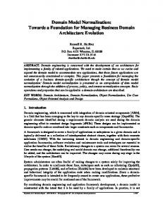
Figure 1. Examples of visual/interactive PDE Editors specialized views can be defined with little coding effort. Sections (1) to (4) in Fig. 1 are all examples for such specialized modeldependent views. Section (1) in Fig. 1 shows a specialized editor for the simple demonstration model of a family tree (close to role models of development processes). Section (2) displays a visual editor for Project Execution Strategies of the V-Modell XT [2, 18]. Section (3) shows an interactive feedback mechanism for process model conformity validation (a task that requires to combine several conceptual and technical sub-models). Section (4) finally shows an editor for V-Modell XT Project Types (an element that is used to configure process tailoring). Fig. 1 also shows bits of the context-specific UI-frame. Similar to the Microsoft Office suite, process engineers are provided with specific sets of operations depending on the actual context of their activity. The editors (1), (2), (4) support drag & drop and can be used intuitively (one can drag elements from the model tree onto the design surface, etc.). The low-level model structures – especially those behind the views displayed in (2) and (4) – are very complex and editing these aspects of the process has been a common source of errors in our projects with industrial or public service partners. Taking the design of tailoring criteria [17] as an example, one would normally not want to (i) have to look up the proper dependency container, (ii) add a new dependency, (iii) look up and pick the dependency source element, and (iv) look up and pick the dependency target element. More intuitive would be to (i) pick a project type, (ii) drag an activity that shall be included in this project type onto some “in-
cluded activities” area. The specialized editor depicted in section (4) of Fig. 1 allows just that and takes care of the lower level model operations behind the scenes – always ensuring a consistent state of the model. Many typical modeling mistakes are thus avoided because they cannot be made. Of course, the user does not have to use the specialized editors and can still edit the model “by hand”. Process Validation Support Model consistency is another area that greatly benefits from the approach of baking the meta-model into the tool. Purely schema-based editors can check for consistency based on the schema. It can for example be ensured that only valid child elements are added below a certain element. This kind of consistency checks are generated into the PDE editor based on the constraints defined in the DSL. Not only does the editor check the validity of the model, it only presents the allowed operations to the user. If the DSL for example does not allow relations between roles and activities, no such operation would be provided at the user interface. Beyond those simple checks it is possible to build in custom rules and constraints – similar to the model-specific editors. This is especially useful for properties of the process model that cannot be expressed in the schema. Examples would be a check for circular references between elements, determination of whether the process terminates or not, whether all work products have a corresponding activity, etc (more on this kind of checks can be found in [18]).
In almost all our process improvement projects, we experienced design errors that caused the export of process documentation or work product templates to fail (e.g. forgotten or incorrect relations). This is a typical translation problem while remodeling a freeform design as discussed with the customer. A whiteboard drawing by nature cannot respect complex and mostly hidden constraints and interdependencies. Guided visual modeling on the other hand provides context-specific artifacts and operations. Invalid artifacts are not available for a specific design task, while missing ones are displayed by the validation.
5.
Conclusion
In this paper we presented our work on the interactive Process Development Environment (PDE), which is based on domain-specific languages. The different layers of DSLs provide a flexible framework for tool development based on a concrete process metamodel. As examples, the V-Modell XT 1.3.x meta-model and a proprietary process model of a large software company have been implemented in the domain meta-model. This model is used to generate the tool framework. The generated design tool supports presentation, graphical modification, and validation of process models. Additionally, the tool framework can be further extended e.g. to provide more sophisticated views or custom design-time validation, thus allowing for a customization that is specific to the metamodel. The presented approach is a significant step towards more “userfriendly” and rapid process design and offers design comfort similar to modern IDEs. Process engineers can work in their domain and in their (graphical) language without having to deal with low-level process model definitions, such as XML documents. This eases the communication to the (non-technophile) stakeholders of the process, too. Ongoing Work We are currently working on a concept to “modularize” the underlying DSLs: Right now the process to be edited has to be defined in one domain meta-model, which can get quite large. The generation of the V-Modell XT work product templates involves a couple of models: The core V-Modell XT plus an additional model that contains text modules to be included in the templates. In the current version of PDE, the meta-models of these two models would have to be combined into one domain-model. The goal is to get an environment that supports a process meta-model family with all its aspects. We are working on support for this kind modularity of models. In addition to the foundational work, we are continuously identifying aspects of the models we work with that could be represented in more sophisticated and intuitive views. Currently we provide views for tasks we consider critical (Fig. 1). But there are many areas left for visual editors. So for instance the design of complex, hierarchical and interdependent artifact structures is a complex undertaking. Sometimes, artifact dependencies reference elements of the model from within another module. This kind of dependencies requires consistency checks because the participating elements are “loosely coupled”. Currently, ascertaining consistency is entirely left to the process engineer. The author has to have an overview over (potentially) the whole model. Another topic of interest is the visualization of process model variants [11, 14] to highlight commonalities and variabilities. Another area of work is the integration of the process design and planning with project setup and support for project runtime. The PET framework [12] is a tool we are using to address this phase of the process life cycle. To support the transition from a process standard to projects we are in the early planning stages for a model that describes the structure of work product templates to be filled with the contents of the process model. It would be another
example for multiple model modules that play together to generate output (freely structured work product templates in this case). Evaluation We are currently introducing the tool in our industrial cooperation projects. We hope to get some (informal) feedback on usability from those partners. Using the tool internally for three different models has already proven to be valuable in our daily work: (1) we can create a customized editing environment quickly to test modeling ideas and (2) editing a model has become easier and less error-prone. The tool was developed based on our requirements – it is no surprise that it suits our needs. A next step is to do a systematic (empirical) evaluation with independent users. We will plan such an evaluation once we have collected the feedback from our “beta users”.
References [1] K. Beck and C. Andres. Extreme Programming Explained: Embrace Change. Addison-Wesley Longman, 2nd edition, 2004. [2] K. Bergner and J. Friedrich. Using Project Procedure Diagrams for Milestone Planning. In Proceedings of the International Conference on Software Process (ICSP), 2010. [3] S. Cook, G. Jones, S. Kent, and A. C. Wills. Domain-Specific Development with Visual Studio DSL Tools. Addison-Wesley Longman, 2007. [4] Eclipse Foundation. Eclipse Project, 2010. http://www.eclipse.org. [5] Eclipse Foundation. Eclipse Process Framework, 2010. http://www.eclipse.org/epf.
URL URL
[6] Federal Ministery of the Interior. V-Modell XT Editor, 2010. URL http://sourceforge.net/projects/fourever. [7] J. Friedrich, U. Hammerschall, M. Kuhrmann, and M. Sihling. Das V-Modell XT. Springer, 2nd edition, 2009. [8] B. Henderson-Sellers. Method Engineering: Theory and Practice. In Information Systems Technology and its Applications, 2006. [9] Joint Technical Committee ISO/IEC JTC 1. Software Engineering - Metamodel for Development Methodologies. Technical Report ISO/IEC 24744:2007, International Organization for Standardization, 2007. [10] P. Kruchten. The Rational Unified Process. An Introduction. AddisonWesley, 2003. [11] M. Kuhrmann. Konstruktion modularer Vorgehensmodelle. PhD thesis, Technische Universit¨at M¨unchen, 2008. [12] M. Kuhrmann and G. Kalus. Providing Integrated Development Processes for Distributed Development Environments. In Workshop on Supporting Distributed Team Work at Computer Supported Cooperative Work (CSCW), 2008. [13] OMG. Software & Systems Process Engineering Metamodel Specification (SPEM) Version 2.0. Technical report, Object Management Group, 2008. [14] D. Rombach. Integrated software process and product lines. In Proceedings of International Software Process Workshop (SWP), 2005. [15] K. Schwaber. Agile Project Management with Scrum. Microsoft Press, 2004. [16] T. Ternit´e. Process lines: a product line approach designed for process model development. In Proceedings of 35th SEAA, 2009. [17] T. Ternit´e and M. Kuhrmann. Das V-Modell XT 1.3 Metamodell. Technical Report TUM-I0905, Technische Universit¨at M¨unchen, 2009. [18] E. Wachtel, M. Kuhrmann, and G. Kalus. A Domain Specific Language for Project Execution Models. In Proceedings of 39th Annual Conference of the German Computer Society, 2009.