Voltage Control in Wind Power Generation Using Doubly Fed Induction Generators E. Toledo*1, L. Aromataris2, G. Tarnowski3, M. Oliveira4, O. Perrone5, H. Reversat6 Energy Study Center to Development (CEED), National University of Misiones (UNaM) Oberá, Misiones, Argentina
[email protected];
[email protected];
[email protected];
[email protected];
[email protected]
*1
6
Electric Power System Analysis Group (GASEP), National University of Río Cuarto (UNRC) Rio Cuarto, Córdoba, Argentina
[email protected];
2
connected during voltage dips (LVRT). [1]
Abstract
Not all wind generation technologies are capable of providing auxiliary services. Within existing technologies, the most widespread is the doubly fed induction generator (DFIG), which has the ability to contribute with reactive power to the network voltage control [2]. In this turbine, the stator circuit is connected directly to the network while the rotor circuit is connected via an electronic converter. The power passes through the converter between 20 and 30% of the nominal power range depending only on the variation of slip and reactive power requirements. The losses in the power electronic converter are reduced, compared with a system where the total power must be converted as in the wind turbine generator which is synchronous. This reduces the cost of the converter which is smaller in size. As it is a variable speed wind machine, it reduces voltage fluctuations in the point of connection to the network and allows having an independent control of the active and reactive power which is delivered to the network [3]. Another benefit is that one can adjust the rotor speed according to the speed of the wind, so that aerodynamic efficiency is optimal. The voltage control through DFIG has been discussed in various papers. Dynamic simulations illustrating the voltage control action in variable speed turbine is presented in [4]. This article compares the different steady‐state current of the rotor‐side converter (RSC), for different scenarios of absorption and generation of reactive power (Q). However, it does not consider the contribution of the reactive power that can be delivered by the grid side converter (GSC). Capacity
In recent years around the world, conventional generation plants are being replaced by wind power plants. The rapid development of wind power generation brings new requirements for the integration of wind turbines to the Electric Power Systems. These requirements establish that the new technologies must provide ancillary services similar to those of conventional plants, such as voltage control in steady state and voltage control during faults occurring close to the wind power plant. This paper explores and compares the performance of two different alternatives of voltage control using doubly fed induction generator (DFIG) topology, which is the most used wind generation technology nowadays. This performance is investigated in a transmission network to a disturbance which endangers the stability of long term voltage thereof. In the first case, the voltage control of the terminal bus of the wind plant will be performed only through the rotor‐side converter, while in the second case; the voltage control will also have the additional contribution of the reactive power delivered by the grid side converter. The results show the importance of this additional contribution of the reactive power to voltage system stability. Keywords Wind Power; Voltage Stability; Voltage Control; Doubly Fed Induction Generator (DFIG); LVRT; Coordinated Control; Reactive Power Control; Control Strategies; DFIG Model.
Introduction The rapid development of wind power generation brings new requirements for the integration of the wind turbines to the grid. These requirements are related to ancillary services that wind turbines can offer, such as voltage control and the ability to remain
JOURNAL TITLE ‐ MONTH YEAR
1
control is performed through the d q axes, which are referenced in the stator system and are orthogonal to each other. Thus, the d component of the rotor current is used to control the reactive power and the q component of the rotor current is used to control the torque of the wind turbine. This control consists of two cascaded PI control. The first is the PQ control, which receives the active and reactive power measured in the network and compares them with the reference, passing later to the PI control that outputs the reference currents. These signals enter the second control, that is to say the current control, which compares these references with the measured currents and after a new PI control, the rotor voltage is changed [7]. The GSC maintains the DC voltage at a set value which is independent of the magnitude and direction of the rotor power. In this case, the converter only exchanges active power with the network. Therefore, the exchange of reactive power from the DFIG is done through the stator. Nonetheless, if an additional PI control that takes into account the error signal voltage is added to the GSC, is possible that the machine can also issue additional reactive power through this converter, increasing the supply of reactive power in situations in which it is required.
limits to deliver reactive power from the DFIG stator is studied in [5], but this study does not consider the contribution of the GSC. Different voltage control algorithms are suggested in [6], in which only the GSC is used, without considering the significant contributions provide by the RSC. This paper compares the behaviour of a highly loaded transmission network whose reactive power requirements are close to the limit available. Under these circumstances, a disturbance will be applied which endangers the stability of long‐term voltage. Not only will the conventional voltage control produced by synchronous machines be considered, but also the voltage control provided by a wind park made up of DFIG turbines. In the first case, it is considered that the voltage control in the terminal bus of the wind turbine will be performed by the rotor‐ side converter (RSC), a system commonly used for this type of machines, providing active and reactive power independently. The grid side converter, GSC, maintains a constant dc‐link voltage and adjusts reactive power absorbed from the grid by the GSC. In the second case, both RSC and GSC converters may control the voltage and provide active and reactive power. The results show that in the second case, the additional power supply can be determinant to maintain the voltage stability of the system. Reactive power capability of DFIG Fig. 1 shows the diagram of a generator DFIG where we can see a mechanical gear system that couples the blades with the asynchronous generator. It can also be observed the direct connection from the stator to the transmission network. The rotor is connected to an electronic converter back‐to‐back which comprises two independent electronic devices separated by a bus which maintains a constant DC voltage level. On the rotor side converter, it can be appreciated the RSC. On the grid side is shown the GSC. Figure 1 shows the schematic diagram of the DFIG system.
a)
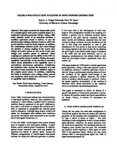
FIG. 2 ‐ POWERFACTORY LIBRARY MODELS. A) MODEL INTEGRATED DFIG B) DFIG DETAILED MODEL
To perform the power system simulations on the electric system being studied and model both types of DFIG controls, the PowerFactory DigSilent software was used. This software has a library model of the DFIG which includes both types of controls. One of the models is integrated, that is to say, the generator and GSC and RSC controls form a block in which the user does not have access to intermediate variables. This model controls the terminal voltage only through the RSC, while the GSC emits or consumes only active power (Fig. 2.a). The library also offers another alternative where the plant components are modeled
FIG. 1 ‐ SCHEMATIC DIAGRAM OF THE DFIG
The rotor side converter, RSC, controls the active and reactive power of the machine independently. This
2
b)
JOURNAL TITLE ‐ MONTH YEAR
separately (Fig. 2.b) [8]. In this way, intermediate controls can be accessed so that the GSC can provide a portion of the reactive power in order to cooperate with the control voltage. Case Study
Motor 1
Motor 2
Motor 3
Power (MVA)
rate
28
28
28
Voltage (KV)
rate
6
6
6
As a case study, a system consisting of 14 buses composed of different elements was considered. In fig. 3, it can be observed its topology.
TABLE 5 ‐ LOADS IN GENERAL
Type of load
Load 1
Load 2
Load 3
static
static
static
Active (MW)
Power
100
75
50
Reactive (MVAr)
Power
50
35
25
6
6
6
Voltage rate (KV)
Simulations The simulations consider two cases: a) The wind farm is modeled by 57 DFIG machines which controls the terminal voltage of the converter through CSR b) The wind farm 57 is modeled by DFIG machines where the terminal voltage is controlled through RSC converters and GSC. The fault that is applied in both simulations corresponds to a short circuit and disconnection phase with clearance in one of the lines of the system. Output curves show the behavior of the network variables for each case: Case 1 ‐ Wind farm voltage control through CSR
FIG. 3 ‐ SYSTEM OF 14 BUSES
The generating park consists of two plants with synchronous machines and a park with wind generation. The demand is concentrated in three buses where 50% of the load was modeled as static and the other 50% as induction motors. The system has six transformers with on load tap charguer(OLTC). Below are the main features of the foregoing: TABLE 1 ‐ SYNCHRONOUS GENERATORS
Generator 1
Generator 2
S rate (MVA)
110
300
V rate (KV)
16,5
18
Controls
IEEEX1 regulator)
(voltage
IEEEX1 regulator)
(voltage
IEEEG3 regulator)
(speed
IEEEG3 regulator)
(speed
MAXEX2 regulator)
(exitation
lMAXEX2 regulator)
(exitation
The base case shows that before the disturbance voltage levels are within acceptable limits. The synchronous machines are generating reactive power to the limit of its capacity. The wind farm is operating at the nominal point of its capacity of active and reactive power. At the time of 1 second, the fault is applied on the line wich connecting the bus 8 and 9. At 120 milliseconds occurs the clearing of the fault and the outage of the line. At 55 seconds, the limiter of overexcitation (MAXEX2) of the synchronous generator 2 acts and the terminal voltage drops progressively to the value corresponding to the admissible field voltage. At 59 seconds, the MAXEX2 of the synchronous generator 1 acts and produces the same phenomenon occurred with the generator 2 (Figure 4). During all this time the transformers with load tap changers acted to recover the voltage on the demand producing, in this way, the
TABLE 2 ‐ WIND FARM Machine type
DFIG 2,22
S rate (MVA) V rate (KV)
0,69
TABLE 3 ‐ TABLE 4 ‐ MOTORS
JOURNAL TITLE ‐ MONTH YEAR
3
suffers a decrease to result in the necessary reactive power which maintains the terminal voltage at the set values (Figure 9). The voltage decreases in the load but the voltage maintained within an acceptable profile for these conditions (Figure 11). In Table 6 the results are shown.
recovery of the active and reactive power of the static Load. This process which finally reached the limit of tap‐changer, needed the contribution of reactive power from generators and caused, in part, the action of the limiters MAXEX2. The wind farm kept their terminal voltages, active and reactive power (Figure 6 and 8) at approximately constant values until the action of MAXEX2 limiters occurred. After this, there is a significant increase of the reactive power to sustain DFIG voltage values at the expense of the decrease of the active power generated thereby. The charging voltages (Figure 10) drop to unacceptable values which are typical in a scenario of voltage instability. This is shown in the following table:
TABLE 7 ‐ VOLTAGE IN THE LOAD BUSES
TABLE 6 ‐ VOLTAGE IN THE LOAD BUSES
Voltage before the fault (p.u.)
Voltage after the fault (p.u)
Load 1
0,96
0,95
Load 2
0,99
0,96
Load 3
0,98
0,95
Voltage before the fault (p.u.)
Voltage after the fault (p.u)
Load 1
0,95
0,84
Output Curves
Load 2
0,99
0,83
Load 3
0,98
0,71
Below are output curves where the figures in a) belong to the first case; while figures in b) belong to the second.
Case 2 ‐ Wind farm with voltage control by RSC and GSC The base case is the same as case 1. At the time of 1 second, the fault is applied on the line connecting bus 8 and 9. At 120 milliseconds occurs the clearing of the fault and the outage of the line. At 79 seconds, the limiter of overexcitation (MAXEX2) of the synchronous generator 2 acts and the terminal voltage drops progressively to the value corresponding to the admissible field voltage. In this case, the action of the limiter occurs later than in the former case due to the additional contribution of reactive power produced by the wind farm (Figure 5). In the case of generator 1, the terminal voltage is maintained due to fact that the provided additional reactive power does not necessitate the protective action of the synchronous generator. Under these conditions, the terminal voltage of the wind farm (Figure 7) can be sustained in the setpoints improving significantly the voltage profile of the entire process. Throughout this process, the on load tap charguer of distribution transformers act but they do not reach the limit. The output powers deliver by the wind farm, show a suitable output to the type of control used where voltage control privileges against the emission of active power. The portion of the active power emitted by the GSC,
4
FIG. 4 ‐ TERMINAL VOLTAGE IN THE SYNCHRONOUS GENERATORS 1 AND 2 (CASE 1)
FIG. 5 ‐ TERMINAL VOLTAGE IN THE SYNCHRONOUS GENERATORS 1 AND 2 (CASE 2)
JOURNAL TITLE ‐ MONTH YEAR
FIG. 6 ‐ TERMINAL VOLTAGE IN THE WIND PLANT (CASE 1)
FIG. 10 ‐ VOLTAGE IN THE LOAD BUSES (CASE 1)
FIG. 7 ‐ TERMINAL VOLTAGE IN THE WIND PLANT (CASE 2)
FIG. 11 ‐ VOLTAGE IN THE LOAD BUSES (CASE 2)
Conclusion One of the most used technologies in wind turbines is the doubly fed induction generator (DFIG) which is capable of contributing to the reactive power control in the network close to the wind plant point of interconnection. In this type of wind turbine generator, the stator circuit is connected directly to the network while the rotor circuit is connected to the network trough a back‐to‐back power electronic converter. As it is a variable speed wind turbine, it allows reducing voltage fluctuations in the point of connection to the network, as well as having an independent control of the generated active and reactive powers. The voltage control by DFIG could be performed through the rotor‐side converter RSC; a system which is commonly used for such machines. This converter provides active and reactive power independently. The grid side converter, GSC, normally maintains a constant dc‐link voltage and adjusts reactive power absorbed from the grid by the GSC. However, it has been proposed in the literature the use of the GSC to contribute to voltage control too and to provide reactive power to the network when it becomes necessary. For situations of long‐term voltage stability, it has been shown in this paper that the simultaneous use of both RSC and GSC controls can provide additional
FIG. 8 ‐ REACTIVE AND ACTIVE POWER GENERATED BY THE WIND PLANT (CASE 1)
FIG. 9 ‐ REACTIVE AND ACTIVE POWER GENERATED BY THE WIND PLANT (CASE 2)
JOURNAL TITLE ‐ MONTH YEAR
5
(CEED). His research interests include stability analysis of power systems, power system modeling and analysis of voltage stability in wind farms. Luis Aromataris was born in Mendoza, Argentina. He received the degree in Electromechanical Engineering from the Universidad Nacional de Rio Cuarto, Argentina and Doctor of Engineering from the Universidad Nacional de La Plata, Argentina. Currently, he is researcher at the Grupo de Analisis de Sistemas Eléctricos de Potencia (GASEP). His research interests include power systems stability and voltage stability analysis with high penetrations of wind farms. Germán C. Tarnowski received the Electro‐Mechanical Engineer degree from National University of Misiones, Argentina in 2003; the MSc. degree in Automation and Control from Federal University of Rio Grande do Sul, Brazil in 2006, and the Industrial‐PhD degree from Technical University of Denmark in 2012. Since 2007 he is with Vestas Wind Systems, where he did his Industrial PhD studies on Coordinated Frequency Control of Wind Turbines. He holds today the position of Research Engineer. His interests involve operation and control of wind power plants, control systems and applications of electrical machines and power electronic converters for renewable energy. Mario O. Oliveira was born in Capioví, Misiones, Argentina in May 1979. He received the degree in Electromechanical Engineering from the National University of Misiones (UNaM), Argentina in 2005 and Masters in Electrical Power Systems from Universidade Federal do Rio Grande do Sul (UFRGS), Brazil in 2009. Currently, he is a researcher at the Energy Study Center to Development (CEED) and associate professor at UNaM. His areas of interest include protection of electrical machines, power system modeling and troubleshooting electrical systems. Oscar E. Perrone was born in Venado Tuerto, Santa Fe, Argentina in December 1954. He received the degree in Electromechanical Engineering from the Universidad Nacional de Córdoba (UNC), Argentina in 1982. Currently, he is a researcher at the Centro de Estudios de Energia para el Desarrollo (CEED), director of Electromechanical Engineering and professor at the Universidad Nacional de Misiones. His areas of interest include measurements and electrical installations
reactive power. Therefore, avoid voltage instability of a system loaded to its reactive power limit, after a strong disturbance is avoided. REFERENCES
Kayikci, M.; Milanovic, J.V.; , ʺReactive Power Control Strategies for DFIG‐Based Plantsʺ, Energy Conversion, IEEE Transactions on , vol.22, no.2, pp.389‐396, June 2007 Transactions on Energy Conversion, Vol. 22, No. 2, June 2007. Vittal, E.; OʹMalley, M.; Keane, A.; , ʺA Steady‐State Voltage Stability Analysis of Power Systems With High Penetrations
of
Windʺ, Power
Systems,
IEEE
Transactions on , vol.25, no.1, pp.433‐442, Feb. 2010 Shuhui Li; Haskew, T.A.; Williams, K.A.; Swatloski, R.P.; , ʺControl of DFIG Wind Turbine With Direct‐Current Vector Control Configurationʺ, Sustainable Energy, IEEE Transactions on , vol.3, no.1, pp.1‐11, Jan. 2012. J. G. Slootweg, S. W. H. de Haan, H. Polinder, and W. L. Kling, “Voltage control methods with grid connected wind turbines: a tutorial review”, Wind Eng., vol. 25, no. 6, pp. 353–365, 2001 A. Tapia, G. Tapia, J. X. Ostolaza, and J. R. Saenz, “Modeling and control of a wind turbine driven doubly fed induction generator,” IEEE Trans. Energy Convers., vol. 18, no. 2, pp. 194–204, Jun. 2003. P. Ledesma and J. Usaola, “Contribution of variable‐speed wind turbines to voltage control”, Wind Eng., vol. 26, no. 6, pp. 347–358, 2002. Poller M, Doubly‐Fed Inducion Machine Models for Stability Assessment of Wind Farms, DIgSILENT GmbH, Germany. Doc.TechRef, “Dynamic Modelling of Doubly‐Fed Induction Machine Wind‐Generators”, Published by DIgSILENT GmbH, Germany, 14 August 2003.
AUTHOR’S INFORMATION Eduardo J. Toledo was born in Resistencia, Chaco, Argentina in August 1986. He received the degree in Electromechanical Engineering from the National University of Misiones (UNaM), Argentina in 2011. He is now a M.Sc student at National University of Rio Cuarto, Argentina (UNRC). Currently, he is researcher at the Energy Study Center to Development
6
JOURNAL TITLE ‐ MONTH YEAR
Jose H. Reversat was born in Jardin America, Misiones, Argentina in November 1963. He received the degree in Electrical Engineering from the Universidad Nacional de Misiones (UNaM) Argentina in 1996 and specialization in Plant Engineering and Production from UNaM in 2000. Currently, he is a researcher at the Centro de Estudios de Energia para el Desarrolo (CEED), and adjunct professor at UNaM. His areas of interest include power systems and electrical installations.
JOURNAL TITLE ‐ MONTH YEAR
7