Accepted Manuscript Volume of fluid model to simulate the nanofluid flow and entropy generation in a single slope solar still Saman Rashidi, Shima Akar, Masoud Bovand, Rahmat Ellahi PII:
S0960-1481(17)30817-0
DOI:
10.1016/j.renene.2017.08.059
Reference:
RENE 9157
To appear in:
Renewable Energy
Received Date: 29 May 2017 Revised Date:
18 August 2017
Accepted Date: 23 August 2017
Please cite this article as: Rashidi S, Akar S, Bovand M, Ellahi R, Volume of fluid model to simulate the nanofluid flow and entropy generation in a single slope solar still, Renewable Energy (2017), doi: 10.1016/j.renene.2017.08.059. This is a PDF file of an unedited manuscript that has been accepted for publication. As a service to our customers we are providing this early version of the manuscript. The manuscript will undergo copyediting, typesetting, and review of the resulting proof before it is published in its final form. Please note that during the production process errors may be discovered which could affect the content, and all legal disclaimers that apply to the journal pertain.
ACCEPTED MANUSCRIPT
1
Volume of fluid model to simulate the nanofluid flow and
2
entropy generation in a single slope solar still
3
Saman Rashidia, Shima Akara, Masoud Bovandb and Rahmat Ellahic,1 Department of Mechanical Engineering, Ferdowsi University of Mashhad, Mashhad 91775-1111, Iran b
5
Department of Engineering, Semnan Branch, Islamic Azad University, Semnan, Iran c
6
RI PT
a
4
Department of Mathematics & Statistics, FBAS, IIUI, Islamabad, Pakistan
Abstract:
9
This paper proposes volume of fluid (VOF) model to investigate the potential of Al2O3-
10
water nanofluid to improve the productivity of a single slope solar still. Accordingly, VOF
11
model is utilized to simulate the evaporation and condensation phenomena in the solar still.
12
An entropy generation analysis is used to evaluate the system from the second law of
13
thermodynamics viewpoint. The effects of solid volume fraction of nanofluid on the
14
productivity and entropy generation in the solar still have been examined. The numerical
15
results are compared with the experimental data available in the literature to benchmark the
16
accuracy of VOF model. The numerical results showed that the productivity of solar still
17
increases with an increase in the solid volume fraction of nanoparticles. The productivity
18
increases about 25% as the solid volume fraction increases in the range of 0% to 5%. There
19
is about 18% enhancement in the average Nusselt number as the solid volume fraction
20
increases in the range of 0% to 5%. Moreover, the maximum values of viscous and thermal
21
entropy generations are happened at the regions around the bottom and top surfaces of the
22
solar still. Both types of entropy generation increase by increasing the solid volume
AC C
EP
TE D
M AN U
SC
7 8
1
Corresponding author (R. Ellahi) e-mails:
[email protected],
[email protected]
1
23
ACCEPTED MANUSCRIPT fraction of nanoparticles. The viscous and thermal entropy generations increase about 95%
24
and 25%, respectively as the solid volume fraction increases in the range of 0% to 5%.
25
Keywords: VOF mode; Solar still; Nanofluid; Productivity; Entropy generation
26
Nomenclature
27
A
28
Bc
29
C
30
df
31
dp
nanoparticle diameter (nm)
32
E
energy (J/kg)
33
F
force (N)
34
g
gravitational acceleration (m/s2)
35
H
height of solar still (m)
36
k
thermal conductivity (W/m.oC)
37
lBF
mean free path of water (-)
38
L
length of solar still (m)
39
mɺ
productivity (Kg/m2)
40
Ng
non-dimensional local entropy generation (-)
41
Nt
mean entropy generation rate (-)
42
Nu
43
p
44
Pr
45
Re
46
S ′g′′
47
Sh
RI PT
surface (m2) Boltzmann constant (-) specific heat (J/kg.oC)
AC C
EP
TE D
M AN U
SC
molecular diameter of base fluid (nm)
Nusselt number (-) Pressure (Pa) Prandtl number (-)
Reynolds number (-) entropy generation rate (W/m3.oC) energy source term (Kg/m.s) 2
Sα
MANUSCRIPT mass source termACCEPTED (Kg/m3.s)
49
t
time (s)
50
T
temperature (oC)
51
u,v
velocity components in horizontal and vertical directions (m/s)
52
V
velocity (m/s)
53
x,y
rectangular coordinates components (m)
54
Subscripts/superscripts
55
Ave
average
56
b
bottom
57
B
Brownian
58
eff
effective
59
f
base fluid
60
g
glass cover
61
i
ith phase
62
l
left
63
p
particle
64
r
right
65
th
thermal
66
v
vapor
67
v
68
Greek symbols
69
α
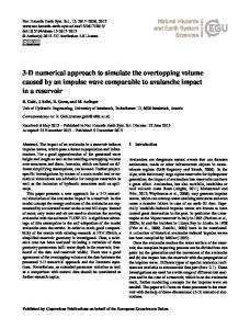
70
δ
distance between particles (nm)
71
θ
slope of the glass cover ( )
72
µ
dynamic viscosity (kg/m.s)
AC C
EP
TE D
M AN U
SC
RI PT
48
viscous
volume/void fraction (-)
o
3
ρ
ACCEPTED MANUSCRIPT density of the fluid (kg/m3)
74
φ
solid volume fraction of nanoparticles (-)
75
Abbreviations
76
CFD
Computational fluid dynamics
77
VOF
Volume of fluid
78
1. Introduction
79
Solar stills are recognized as the most efficient desalination technology, which utilize solar
80
radiation to desalinate water and generate drinking water. These devices are usually cheap
81
and have a simple structure with insignificant maintenance cost. As a matter of fact the
82
solar energy is used as a free, stable, and trusty source of energy. However, these devices
83
have a low performance. Consequently, there is a necessity to recover the performance of
84
solar stills by using active and passive methods. The active methods need external source
85
of energy such as applying heat pipe and thermoelectric module [1, 2], put on flat-plate
86
solar collector and cooling glass cover [3], using parabolic concentrator [4], by means of
87
water sprinkler [5] and via heater [6] are a number of active techniques used to improve the
88
efficiency of solar stills. Aside from active method, some researchers used passive methods
89
to enhance the efficiency of solar stills. Most common of these methods are installing fins
90
[7], blade in solar still [8, 9], porous materials [10, 11], PCM [12], baffles [13] and
91
applying vapor adsorbent pipe network [14] and so on.
92
Common liquids such as water have almost small value of thermal conductivity and thus
93
cannot achieve acceptable heat transfer rates in thermal systems. A method to overcome
94
this defect is adding nanoparticles in such liquids in order to enhance their thermal
95
conductivity. Some researchers used this technique in different solar systems, for instance
96
Mahian et al. [15] evaluated the applications of them in solar systems in a review paper.
AC C
EP
TE D
M AN U
SC
RI PT
73
4
They reported that applyingACCEPTED nanofluids inMANUSCRIPT solar collectors has some economic and
98
environmental advantages as they cause a decrease in CO2 pollution and fuel savings.
99
Some investigators have used nanoparticles inside the solar still as a passive technique to
100
improve the performance of this device. Kabeel et al. [16] used the nanofluid in a solar still
101
integrated with external condenser. The productivity of their solar still was increased about
102
116% and 53.2% by using the nanofluids and external condenser, respectively. Kabeel et
103
al. [17] applied nanofluids and vacuum simultaneously in an experimental work to enhance
104
the efficiency of a solar still. Their results showed that these techniques enhance
105
considerably the evaporation and condensation rates and accordingly, cause a more
106
productivity. Sahota and Tiwari [18] examined the influence of nanofluids on the
107
efficiency of a double slope solar still. They observed the higher thermal energy efficiency
108
and thermal exergy for nanofluids in comparison with the case of pure water. Elango et al.
109
[19] inspected experimentally the effects of various water nanofluids containing Al2O3,
110
ZnO, Fe2O3, and SnO2 on the efficiency of a single slope solar still. They concluded that
111
Al2O3-water nanofluid, with 29.95% higher productivity in comparison to the water, has
112
the maximum productivity among all nanoparticles considered in this research. Sahota and
113
Tiwari [20] studied the influence of Al2O3 nanoparticles on the efficiency of a passive
114
double slope solar still. They observed about 12.2% enhancement of yield for 35 kg
115
basefluid by adding Al2O3 nanoparticles with 0.12% concentration. Sahota and Tiwari [21]
116
used Al2O3, CuO, and TiO2-water nanofluids in a double slope solar still. They concluded
117
that the optimization of concentration of nanoparticles depends on the climatic conditions
118
containing the ambient temperature and solar intensity. El-Said et al. [22] coupled a hybrid
119
desalination system with Al2O3-water nanofluids solar heater. They reported that the solar
120
water heater efficiency is about 49.4%. Sharshir et al. [23] used nanofluids and glass cover
121
cooling simultaneously in an experimental research to improve the efficiency of a solar
AC C
EP
TE D
M AN U
SC
RI PT
97
5
still. They used copper oxideACCEPTED and graphite MANUSCRIPT as the nanoparticles. They reported a daily
123
efficiency of 30% for the non-modified still. They recorded 46% and 49% for the daily
124
efficiencies of the still by applying copper oxide and graphite particles with glass cooling,
125
respectively. Kabeel et al. [24] reported both theoretically and experimentally the effects of
126
nanofluids and external condenser on the performance of a solar still. They used aluminium
127
oxide and cuprous oxide as the nanoparticles. They concluded that the daily efficiency of
128
the modified still is 84.16% and 73.85% when applying cuprous oxide and aluminium
129
oxide nanoparticles, respectively, with operating the fan. Additionally, the daily efficiency
130
of their conventional still was about 34%. Sahota et al. [25] analytically investigated the
131
influences of Al2O3, CuO, and TiO2-water nanofluids on the efficiencies of the active solar
132
distillation systems. They coupled the double slope solar still with photovoltaic thermal flat
133
plate collectors and helical heat exchanger. They observed a higher productivity by using
134
CuO-water nanofluid in comparison with Al2O3 and TiO2-water nanofluids. Sahota et al.
135
[26] presented the influences of Al2O3, CuO, and TiO2-water nanofluids on the exergy of a
136
double slope solar still. They found that the exergy of the solar still increases by using the
137
nanofluid. Mahian et al. [27] investigated the influences of nanofluids on the evaporation
138
rate in a solar still equipped with a heat exchanger. They used Cu and SiO2-water
139
nanofluids. They reported that at high temperatures, employing SiO2-water nanofluid,
140
which has a lower effective thermal conductivity in comparison with Cu-water nanofluid,
141
causes the higher performance. Sahota and Tiwari [28] performed exergoeconomic and
142
enviroeconomic analyses for a hybrid double slope solar still. Their analyses were
143
performed for three cases containing hybrid solar still operating without heat exchanger
144
(case A), hybrid solar still operating with helically coiled heat exchanger (case B), and
145
conventional solar still (case C). They used Al2O3 and CuO-water nanofluids. They
146
observed that CuO-water nanofluid has better annual performance and exergoeconomic
AC C
EP
TE D
M AN U
SC
RI PT
122
6
ACCEPTED MANUSCRIPT and enviroeconomic for the cases A and B, while, Al2O3-water nanofluid has better results
148
for the case C. Chen et al. [29] studied stability, optical characteristics, and thermal
149
conductivity of SiC-saline water nanofluids used in a solar distillation system. Their
150
results showed that enhancing the salt concentration have some negative influences on the
151
stability and thermal conductivity of nanofluid used in a solar distillation system.
152
There are many experimental works to investigate the potential of nanoparticles for
153
enhancing the productivity in solar stills. Usually, experimental techniques are expensive
154
and time consuming. Accordingly, it is essential to consider a low cost and quick technique
155
to investigate the interesting phenomena in solar stills. Computational fluid dynamics as a
156
worthy method can be used in this regard. Some researcher applied this method for the
157
conventional solar stills [30-32]. Rahbar and Esfahani [31] used CFD method to obtain the
158
productivity and convective heat transfer coefficient of a single slope solar still. They
159
found that the accuracy of the CFD technique to obtain the convective heat transfer
160
coefficient is superior in comparison with the productivity prediction. Rahbar et al. [32]
161
repeated this problem for a tubular solar still. They reported about 200% enhancement in
162
the productivity as the glass temperature reduces only 50 C. Lately, Rashidi et al. [9] used
163
numerically a blade in a single slope solar still. They concluded that using a blade inside
164
the still creates a higher number of vortices with smaller sizes. Smaller vortices create
165
enough pathways to transfer the thermal energy between the glass and water surfaces and
166
enhance the still productivity.
167
All numerical researches performed for solar still used the moist air model. In this model,
168
evaporation and condensation phenomena are not simulated in solar still and fluid is only
169
supposed as a moist air. However, an actual two-phase flow with a vapor-liquid phase
170
change process is occurred in a solar still. This is the main darkness of the moist air model
171
for modelling a solar still.
AC C
EP
TE D
M AN U
SC
RI PT
147
7
ACCEPTED MANUSCRIPT Volume of fluid based CFD has a capability to overcome this darkness for solar stills and
173
models the vapor-liquid phase change. This model can be used to follow the interface
174
between liquid and vapor phases. It has an ability to simulate mass and heat transports
175
through interface. This model has been used for various two-phase problems. Ganapathy et
176
al. [33] applied this technique to model the condensation heat transfer in the microchannel.
177
They compared the results obtained by VOF method with some available universal
178
predictive correlations. They found a good agreement between these results. Ding et al.
179
[34] used a VOF technique to model the vapor-liquid phase change with numerical
180
oscillation suppression. They used the energy source donor-acceptor procedure to suppress
181
the numerical oscillation. They found that there is a good matching between the results for
182
phase change obtained by VOF model and theoretical methods for higher values of mass
183
transfer coefficient. Arunkumar et al. [35] determined air-water two-phase flow regimes by
184
utilizing infrared sensor and VOF methods. They utilized high-speed videography to
185
perform a comparison between the results of infrared sensor and VOF method. They found
186
a good matching between two results. Some relevant studies on the topic of nanoparticles
187
can be found in [36-39] and several references therein.
188
The literature review indicated that researchers used mostly moist air model in solar stills.
189
Moreover, most of researchers investigated experimentally the potential of nanoparticles
190
for improving the performance of solar stills and the numerical activities are rarely
191
presented for this topic. Determination of local entropy generation in a thermal system
192
such as a solar still is essential to detect the regions with high values of irreversibilities.
193
This paper tries to cover above points and uses the volume of fluid model to simulate the
194
nanofluid flow and entropy generation in a single slope solar still.
AC C
EP
TE D
M AN U
SC
RI PT
172
195 196
8
ACCEPTED MANUSCRIPT 2. Description of the problem
198
The solar still under simulation is disclosed schematically in figure 1. As disclosed in this
199
figure, a solar still with the height of the left side (Hl=0.1m), the height of the right side
200
(Hr=0.47m) and the length (L=0.98m) is modeled. A glass cover with angle (θ=20o) and
201
temperature of Tg=30°C is placed as top side. Furthermore, the bottom surface has a
202
constant temperature of Tb=40°C and two sidewalls are adiabatic. At initial time, the water
203
depth is 2cm. It should be stated that the solar irradiance spreads inside the still after
204
absorbing and reflecting by the glass cover. After that, this irradiance is absorbed by water
205
in the still. Finally, it is supposed that the flow to be two dimensional, two phase, laminar,
206
and time dependent.
M AN U
SC
RI PT
197
Insert figure 1 here
207 208
3. Mathematical modelling
209
3.1.
210
In current paper, the volume of fluid model presented by Hirt and Nichols [40] is employed
211
to model the condensation and evaporation phenomena in the solar still. Commonly, this
212
model is employed to model a two-phase flow where the alteration of joint surface between
213
two phases is serious as the vapor-liquid interface can be followed by employing volume
214
of fluid model. In this model, it is necessary to obtain the volume fraction in any cell of
215
domain. The sum of the volume fraction for liquid or vapor phase in a cell should be unity
216
as follows: nphase
217
∑α i =1
i
AC C
EP
TE D
Governing equations
=1
(1)
218
where α indicates the volume fraction and i shows the ith phase. The viscosity of a vapor-
219
liquid two-phase flow in any cell is obtained by employing the mean values of the vapor
9
220
MANUSCRIPT and liquid phases, weighted byACCEPTED their relevant volume fractions. As a result, the viscosity of
221
a vapor-liquid two-phase flow can be given by [41]:
222
µ = α v µ v + (1 − α v )µ eff
223
where µ denotes the viscosity. The subscripts v and eff in this equation denote the
224
properties of vapor phase and nanofluid as liquid phase, respectively. A single phase
225
approach is used to determine the properties of nanofluid. These properties are presented at
226
the appendix section. The identical trend can be utilized to obtain the density or thermal
227
conductivity of a vapor-liquid two-phase flow. The tracking of the interface between two
228
phases is performed by solving a continuity equation for the volume fraction of two
229
phases. This equation is presented as follows:
RI PT
SC
M AN U
230
(2)
∂α i S + V∇.α i = αi ∂t ρi
(3)
where ρi is the density of the ith phase. Moreover, V and t are the velocity and temperature,
232
respectively. Mass transport between vapour and liquid phases for the condensation and
233
evaporation phenomena in the solar still is considered by applying Sαi as the source term in
234
Eq. 3. A single momentum equation is considered for all over the computational domain,
235
and the resulting speed field is shared among the phases. The momentum equation is given
236
by:
EP [
]
∂ ∂t (ρV ) + ∇.(ρVV ) = −∇p + ∇. µ eff (∇V + ∇V ′) + ρg + F
AC C
237
TE D
231
(4)
238
where F denotes the surface tension forces at the joint surface between two phases [42].
239
Moreover, p is the pressure. These forces create due to exist of the attractive forces
240
between molecules in a fluid. They act for balancing the radially inward inter-molecular
241
attractive force with the radially outward pressure gradient force through the interface. It
242
should be stated that the gravity term (ρg) in above equation has a capability for making
243
the natural gravitational drag to condense vapor into pure water to drop out. The energy 10
244
ACCEPTED equation is shared among the phases. TheMANUSCRIPT energy equation can be presented in the
245
following form:
∂ (ρE ) + ∇.[V (ρE + p )] = ∇.( k∇T ) + S h ∂t
246
(5)
where k is the thermal conductivity. In above equation, the energy E and temperature T are
248
used as mass-averaged parameters:
RI PT
247
n phase
E=
249
∑α ρ E i =1 nphase
i
i
(6)
∑α ρ i
i
SC
i =1
i
Note that the source term Sh is used in the energy equation to model the heat exchange
251
during the phase change process (evaporation or condensation processes).
252
3.2.
253
The following boundary conditions are employed for this case:
254
•
Boundary conditions
u = v = 0, T = Tg = 300 C
255
TE D
Along the glass cover:
M AN U
250
256
where the subscript g denotes the glass cover.
257
•
260
EP
•
∂T =0 ∂x
(8)
Along the bottom wall:
AC C
259
Along the side surfaces: u = v = 0,
258
(7)
u = v = 0, T = Tb = 40 0 C
(9)
261
where the subscript b denotes the bottom surface of the solar still.
262
3.3.
263
The average Nusselt number:
Parameter definition
11
264
H ave L ∂T Nuave = − L(Tw − Tg ) ∫0 ∂n
ACCEPTED MANUSCRIPT dx
(10)
water
where n is normal direction to the water surface. L is the length of the still. Moreover, Heve
266
is the mean height of the still ((Hr+Hl)/2).
267
The local volumetric viscous entropy generation:
268
2 2 2 µ ∂u ∂v ∂u ∂v S g′′′,v = 2 + + + T ∂x ∂y ∂y ∂x
(11)
where u and v are the velocity components in x and y directions.
270
The local volumetric thermal entropy generation:
272
273
(12)
The dimensionless local entropy generation:
Ng =
2 S g′′′H ave
k
where k is the thermal conductivity.
275
The average entropy generation rate:
1 ∫ ( N g )dA A A
(13)
(14)
EP
Nt =
TE D
274
276
M AN U
271
∂T 2 ∂T 2 + ∂x ∂y
SC
269
k S g′′′,th = 2 T
RI PT
265
where A is the surface of the still.
278
4. Numerical method
279
A numerical method based on finite volume technique is considered for solving the
280
mentioned equations. Staggered mesh arrangement is employed for storing the velocity and
281
pressure terms at the cell faces and cell center, respectively. Furthermore, the SIMPLE
282
algorithm presented by Patankar [43] is employed to couple the pressure and velocity
283
terms. Second-Order Upwind technique is considered to discretize all equations. The
284
convergence criteria are acceptable when the summation of residuals to be smaller than 10-
AC C
277
12
ACCEPTED for all equations. All simulations in this MANUSCRIPT paper are developed employing the Ansys-
285
6
286
Fluent.
287
4.1.
288
The mesh generated within the modeled solar still is disclosed in figure 2. It can be seen
289
that a two-dimensional square grid with non-uniform distribution is considered for this
290
problem. This mesh is refined near the regions with large values of gradients such as near
291
the walls and interface between two phases. A mesh independent test is performed here to
292
guarantee that the results are independent of grid size. Four mesh numbers containing
293
10000, 20000, 40000, and 80000 are considered to perform this test. The relevant water
294
productivity for each mesh number and the percentage difference between them are
295
presented in Table 1. As presented in this table, the difference in water productivity
296
between the mesh numbers of 40000 and 80000 is only 0.3%. As a result, the mesh number
297
of 40000 is considered for the rest modeling.
M AN U
SC
RI PT
Mesh independent test and validation
Insert figure 2 here
299
Insert table 1 here
TE D
298
To evaluate the accuracy of the volume of fluid model, the results achieved by this model
301
are compared with the experimental data of Rashidi et al. [44]. The validation is performed
302
for a conventional solar still without applying nanofluid. The results of this comparison are
303
presented in Table 2. It can be seen that the results achieved by volume of fluid model have
304
a good agreement with experimental data with maximum error of 16%. There is always a
305
discrepancy between the numerical and experimental results. This error is created due to
306
the following reasons:
307
•
AC C
EP
300
The discrepancy is created by some experimental factors containing calibrating
308
equipment for lab measurements, experiment accuracy, human errors, missing out
309
some processes, etc.
13
310
•
ACCEPTED MANUSCRIPT The discrepancy is created by some numerical errors. These numerical errors are created by considering some simplification assumptions such as two dimensional
312
modelling. Moreover, it is assumed that the side walls of the solar still are adiabatic in
313
this numerical modelling. However, they were not completely adiabatic in the
314
experiments. Insert table 2 here
315
RI PT
311
5. Results and discussion
317
In this section, the results of this study are presented to investigate the potential of Al2O3-
318
water nanofluid to improve the productivity of a single slope solar still.
319
Figure 3 shows the contours of water vapor fraction during time for conventional and
320
modified stills by using Al2O3-water nanofluid at φ=5%. The red and blue colours in these
321
contours denote the liquid and vapor phases, respectively. It can be seen that the contours
322
have a stable level for liquid fraction at the bottom region of two stills at the start time (See
323
contours for first row). Phase change is happened and vapor creates during time as the
324
volume fraction of the vapor phase is increasing during time. This phase change is
325
happened due to rise in the water temperature within two stills. The vapor arises from the
326
water surface and transfers toward the glass cover due to the free convection and buoyancy
327
force generated in the still. The vapor contacts with the glass cover and due to the low
328
temperature of this surface, the condensation is occurred and distilled water can be
329
generated. It should be stated that the amounts of the evaporation and condensation heat
330
transfers are improved by adding the Al2O3 nanoparticles in the still as the volume fraction
331
of liquid phase is more in comparison with the conventional still (φ=0%). Note that the
332
thermal conductivity of the fluid enhances by adding the nanoparticles. This leads to
333
increase in the convective and evaporative heat transfers in the still. Moreover, the
334
fluctuating movements of the nanoparticles in the water enhance the heat transfer rate.
AC C
EP
TE D
M AN U
SC
316
14
ACCEPTED MANUSCRIPT Insert figure 3 here
335
Figure 4 shows the variations of productivity with solid volume fraction of nanoparticles
337
for two values of temperature difference between surfaces of water and glass cover (e.g.
338
4°C and 10°C). Using all numerical data, the following empirical equation was derived for
339
the productivity:
340
0.21 0.7486 mɺ = 0.8176+ 0.0391× (Tb − Tg ) × (ϕ)
RI PT
336
(15)
Note that for obtaining this equation, the simulations are performed for four values of
342
temperature difference containing 4oC, 6oC, 8oC, and 10oC at 1%