Web Dynpro: Context Mapping and Model Binding Matthias Weidlich Seminar System Modeling 2005 Hasso-Plattner-Institute for Software Systems Engineering
[email protected]
Abstract
be explained. The first part ends with a short description of the approaches for context programming. In the second part the focus will turn to the dataflows in a Web Dynpro application. Therefore the three different dataflow types, Data Binding, Context Mapping and Model Binding, will be introduced. After the questions of the model origin will be answered, communication scenarios are illustrated. Finally the main points about dataflows in Web Dynpro will be concluded.
In this paper the main concepts and basic technologies concerning data management in Web Dynpro are described. After the context concept has been explained, the focus turns to the different types of dataflows in a Web Dynpro application. Therefore the mechanisms Data Binding, Context Mapping and Model Binding will be discussed. Completing the given impression of the link between frontend system and backend system, the import of models and their connections at runtime will be characterized.
2. Context Concept 1. Introduction
2.1. Utilization of Contexts
With the launch of the NetWeaver platform, SAP introduces a new framework for developing browser based user interfaces, Web Dynpro. As it claims to be the user interface technology for all applications within the scope of NetWeaver, it comprises many complex concepts, such as a generic, platformindependent meta model oriented on the Model View Controller (MVC) design pattern. An introduction into these general concepts can be found in [9, 12]. Referring to [5], Web Dynpro allows the separation of design decisions, navigation issues and data modelling, which includes the concepts to store and transport data inside an application. Context Mapping and Model Binding, mentioned in the title, are two mechanism for data passing in Web Dynpro. Nevertheless this paper focuses not only on these issues, but also explains the basic principles concerning data management. That is why the article is divided into two parts. Firstly the context concept, the main concept regarding data storage in Web Dynpro, will be discussed. On account of this the utilization and the structure including the most important properties will
A Web Dynpro application consists of active parts, the controllers, and passive parts the contexts. Moreover each controller, for instance a view controller or a custom controller, has its own context. Although all data used by the controller or views is stored in the corresponding context, another aspect is even more important. Contexts are used as interfaces to pass data from the frontend, the user interface, to the backend system and vice versa. That brings us to the question, how these contexts are structured.
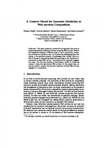
2.2. General Context Structure Contexts are always structured as a tree, consisting of nodes (the non-leafs) and attributes (the leafs), as it is shown in the Entity Relation Model in figure 1 on the following page. Each context has a root node, underneath the data fields are stored. Although the name implies something different, the root node is not a usual node, but a pointer that simply defines the entry point into the tree. That is why the cardinality is unchangeable, set to 1..1 (see also 2.3). Both types of context elements, subnodes and node attributes, exists 1
sents either an individual instance2 of an object type or a list of instances at runtime [2]. This property of a node is called cardinality, which is specified via “minimal appearance .. maximal appearance” and can take on four values: !
• 0..1 The node contains only one element instance, which have not to be instanced. !
• 1..1 Again the node contains only one element instance, but this time it has to be instanced. • 0..n The node is called multiple node and can contain several element instances, of which none have to be instanced. • 1..n Again the node is a multiple node and can contain several element instances, of which at least one have to be instanced.
Figure 1. Context Structure in two flavours: a model and a value flavour. The difference is not only a varying set of properties. In addition value nodes have no binding to the Web Dynpro model (the model will be explained in 3.4), the typical services existing for a model node, like data transfer to the model, are not available for the value node. The same term is endowed for value attributes and model attributes. Since it is not possible to discuss all properties of context elements within the scope of this article, in the next part the focus will be laid on the most important ones. The property name should be self-explanatory, it contains the name of the context element that have to be unique in the whole project. As type declares the data type of a value attribute it can be a Java Native Type. Nevertheless Java Dictionary Types1 are even better to use as attribute types, due to the possibility to attend a Data Binding.
According to the possibility to define multiple nodes, a mechanism to mark a specific element instance in the list is necessary. For that reason each element in an instance list belonging to a value node has a boolean property called leadSelection. This property can be set true for only one element of the list at one time. If nothing else is specified, the first element of the list is automatically assigned the lead selection property.
2.4. Calculated Attributes A special type of value attributes are the calculated attributes. Hence these attributes are not stored as memory objects at runtime, they are automatically calculated by the Web Dynpro Runtime on demand. This demand can be triggered by the Web Dynpro Runtime or some controller coding by accessing the attribute. After setting the property calculated true, the body of a setter- and a getter-method is generated and the developer has to add the calculation part. A short code example for a calculated attribute can be seen on figure 2. It shows how a full name of a person can be calculated by simply combining the first name and the last name.
2.3. Cardinality and LeadSelection Causing the fact that the context is a data model that describes entities and relations, each node repre1 The Java Dictionary contains central, platform- and source code independent type descriptions, including meta data for database objects and user interfaces.
2 To be accurate it has to be said that the individual instance is also embedded in a singleton list.
2
cific context) and IWDNode (to modify, respectively create a context node). The typecasted APIs, the second type of provided APIs, are generated automatically for all statically defined context elements. These interfaces are typecasted, meaning that the signatures of the methods already contain the corresponding object types respectively Java Dictionary Types. The typecasted interfaces, for instance IContextNode (the interface to modify a specific node) or IContextElement (to modify a specific node element), are derived from the global interfaces.
! " " !
#
$
% &
Figure 2. Calculated Property Code Example
2.5. Singleton Property and Supply Functions
3. Web Dynpro Dataflows
Another important property is the singleton property that can be found in value nodes as well as in model nodes. Unlike the cardinality of a node, which describes the number of possible elements within the node, the singleton property determines whether these elements are set for all elements of the parent node3 (non-singleton) or for exactly one element of the parent node (singleton) [2]. The affiliation of these singleton elements is realized in the following way: the singleton elements correspond to the parent node element which is highlighted by the property leadSelection (as it was described in 2.3). Therefore a change of the lead selection in the element list of the parent node makes it necessary to update the data in the singleton elements. For that reason a special type of controller methods for filling value nodes with elements exists, the Supply Functions. These functions are called by the Web Dynpro Runtime whenever the element list of the associated node is accessed. Although each node can have a Supply Function they are mainly used in connection with singleton elements. The data origins used to fill the singleton elements can be various, for instance other elements of the current context.
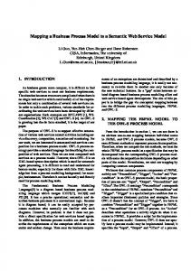
3.1. Overview In this chapter the three types of dataflows in a Web Dynpro application, the Data Binding, the Context Mapping and the Model Binding, will be explained. Before the focus turns to the structural details the relevance of these dataflows should be motivated. On the one hand the Data Binding realizes the link between the user interface and the data structures behind, in the sense of ordinary input- and output mechanism. On the other hand it allows controlling the appearance of the user interface by the data structures. The Context Mapping, which enables data to be circulated between contexts, is mainly used to make the data persistent, due to the limited lifetime of view controllers. An example for such a usage can be found in [5]. Moreover the Model Binding connects the internal data structures of a Web Dynpro application with the model that represents the backend system (see also 3.4). Furthermore it is necessary to envision the structure of a typical application which is shown in the block diagram in figure 3. The Web Dynpro Runtime embeds the application, which consists of agents, for instance a view controller, a custom controller and a model agent. To keep the diagram concise, the application consists of only one controller of each type and some parts (e.g. interface controller and component controller) are not even shown at all. Additionally there is a big storage containing several smaller storages. As it was already mentioned, every controller has its own context, in this case the view controller context and the custom controller context. Moreover the view layout contains the properties of the user interface elements, while the structure of the model is depicted in 3.4. Pointed out by the figure, the big unnamed storage is fragmented by the four smaller storages. Accordingly the imagination
2.6. Context APIs While Supply Functions only deal with the instances belonging to a context node, there also has to be the possibility to change the structure of the context by programming. On account of this Web Dynpro provides two different types of Application Programming Interfaces (APIs). The first one is the set of generic APIs which are needed for the dynamic creation of new context elements at runtime. Examples for generic APIs are the global interfaces IWDContext (to gain access to a spe3 A parent node of a context element is the node, which is located directly above the element in the hierarchical structure.
3
#
$
"
!
(
'
)
*
& %
%
Figure 3. Overview of Dataflows
4
of multiple interfaces, used to access the big storage, is appropriate. Several numbered storage elements are available in more than one storage hence the four named storages overlap in some areas. Concerning the dataflows these are the interesting parts, that will be introduced in the following sections.
context belongs to, they can be regarded as local variables. After a Context Mapping has been defined between two context elements located in different contexts, one and the same context element is visible in both contexts. Similar to the Data Binding a Context Mapping does not require any data transport, because the same storage is assigned for mapped elements. In figure 3 the Context Mapping involves the view controller context and the custom controller context. The storage elements with the number 5 and 8 are context elements that have not been mapped. In contrast, the elements with the number 3, 4, 6 and 7 are mapped, whereas the elements 3 and 4 are also bound with a Data Binding as it is described in 3.2.
3.2. Data Binding The first dataflow to discuss is the Data Binding involving the view layout and the view controller context. Data Binding allows the use of context attributes of the view controller as properties of user interface (ui) elements. Referring to figure 3 the storage elements with the number 2, 3 and 4 participate in the Data Binding, while the storages with the number 1 and 5 are ui element properties, respectively context elements that have not been bound. On account of the binding any user change to the ui element properties, e.g. the text property of an edit field, is immediately visible in the context. Due to the assignment of the same data storage, there is no necessity of data transport.
Figure 4. Data Binding Figure 5. Context Mapping
As it is shown in figure 4 the Data Binding can be defined with value attributes as well as model attributes if the attribute’s type is a Java Dictionary Type. In the specific case that the ui element property is a field of values (e.g. the entries in a table) the parent node of the bound attribute has to be a multiple node, regarding 2.3. If a single property value is bound to an attribute of a multiple node, the leadSelection highlights the value that has to be shown.
The figure 5 shows that a Context Mapping on the one hand can be defined either between value nodes or between model nodes, but not between a single value node and a single model node. On the other hand value attributes can be mapped only to value attributes. For model attributes the same rule is applied. Additionally the following constraint has to be satisfied: a mapping between the parent nodes of two attributes is a precondition for a mapping between these attributes. Moreover Context Mapping is a directive relation. Although the direction has no impact on data changes, because it is irrelevant in which context the changes
3.3. Context Mapping The mechanism used to pass data from one context to another is called Context Mapping. As context elements are in general only visible for the controller the 5
are made, modifications of the mapping relation have to be done at the context in which the mapping relation starts. Consequently the context that is mapped does not even have any knowledge about the mapping at all. Nonetheless it is necessary to define a usage relation between the controllers, whose contexts should participate in a Context Mapping.
In the probable case that structure information are available not until runtime, it is also possible to define the Model Binding dynamically at runtime. Therefore the access to the model classes is gained via generic methods, so that the identification of model elements is exclusively based on their names.
3.4. Web Dynpro Model
The Model Binding is used to access the model and for that reason it links the model with a controller context. In the example application shown in figure 3 on page 4, the Model Binding is defined between the custom controller context and the model. Thus the storage elements with the number 4, 7 and 9 participate in the Model Binding. In contrast, the storage with the number 8 is a context element, that has not been bound, while the storage with the number 10 is an unbound model element. As it was already discussed for the Data Binding and Context Mapping the assignment of one storage address for both bound elements redundantizes any data transport.
3.5. Model Binding
Figure 6. Web Dynpro Model Before the focus turns to the third type of dataflow, the Model Binding, the Web Dynpro model itself should be discussed. The model is a data structure that represents the data and the functionality of the backend, for instance a web service provider or a ABAP 4 backend server. As it can be seen in figure 6, the model consists of model classes which on their part contain other model classes and model attributes. The model classes are Java classes which can be grouped in executable and non-executable classes. Nevertheless they all have to implement the Common Model Interface (CMI), an interface that affects mainly data management and event handling [8]. If the structure of the model is already known at design time, the CMI implementing model classes contain typed getter- and setter-methods similar to Java Beans5 . Therefore a typed access to the classes is provided. The availability of information about the model structure allows it to declaratively define a Model Binding in the way it is described in 3.5.
Figure 7. Model Binding Regarding figure 7, on the one hand context model attributes can be bound to attributes of the model. On the other hand context model nodes can be bound to model classes. Similar to the Context Mapping, it is necessary to state a Model Binding relation between the parent node of a context model attribute and the parent model class of the model attribute to bind the attributes.
4 Advanced Business Application Programming (ABAP) is a programming language created by SAP, which is positioned as the language for programming SAP’s Web Application Server. 5 Java Beans are reusable software components, for which a specification have been defined by Sun Microsystems.
6
3.6. Model Import and Connections to the Model
J2EE based Web Dynpro Runtime [9]. To call procedures from a J2EE backend server, Remote Method Invocation (RMI) is used. The data transfer to a web service is done via SOAP, which is described in detail in [10]. Moreover a ABAP backend server can not be accessed directly. For that reason a middleware component named SAP Java Connector (JCo) is required to generate RFCs out of Java calls and vice versa.
As it was already mentioned in 3.4, all model classes have to implement the CMI. Usually the model classes are generated by an import wizard, on account of this the developer does not have to care about the correct implementation of the CMI. Depending on the type of the used backend system, the import wizard can create the model classes out of different model descriptions.
!" # $
!
"
#$
Figure 9. Connection to Model (J2EE based)
! " #
Figure 8. Model Import In figure 6 the four possible import types are shown. If the Web Dynpro application should use a web service, the model classes will be created out of the WSDL6 description. Concerning the case the developer wants to use existing Web Dynpro UML models a description in the XMI 7 format has to be available, while a RFC8 model is needed to call RFCs directly in an ABAP system. The source code of Java Beans is directly parsed by the import wizard due to the similar structure of Java Beans and model classes implementing the CMI. On account of the two flavours of the Web Dynpro Runtime the possibilities to communicate with the model at runtime are potentially restricted. Figure 9 illustrates the conceivable communication flow for the
Figure 10. Connection to Model (ABAP based) In contrast to the J2EE flavour, the ABAP flavour of the Web Dynpro Runtime is restricted in its communication to web service providers and ABAP backend servers [9]. While the data exchange with web services works in the same manner as with the J2EE flavour, the ABAP backend system can now be accessed directly. Therefore the Business Application Programming Interfaces (BAPIs), which are standardized methods to gain access to SAP Business Objects, can be called via RFCs.
6 The
Web Service Description Language (WSDL) is an XML format published by the World Wide Web Consortium (W3C) for describing web services. 7 XML Metadata Interchange (XMI) is an OMG (Object Management Group) standard for exchanging metadata information via XML. 8 Remote Function Calls (RFCs) are a standardized mechanism for communication between applications on SAP systems as well as non-SAP systems.
4. Summary In conclusion the contexts are the main concept for the storage, handling and management of data in Web Dynpro. As contexts describe entities and their relations, they define the structure, the data model, in 7
which all values will be stored. Advanced design mechanism, for instance singleton nodes, allow creating complex data structures according to the project domain. Although much of the data modelling can be done declaratively, the data structure can also be modified by context programming at runtime. In addition, there are three possibilities to realize dataflows in Web Dynpro. Data Binding creates the link between the properties of user interfaces and controller contexts, that can be connected to another context via Context Mapping. The data and functionality of the backend system, represented by the Web Dynpro model, can be accessed by defining a Model Binding. Hence the employed backend system can be a J2EE server, an ABAP server or a web service provider, an import wizard automatically creates the suitable model that abstracts the type of the backend system. Due to this, the discussed data management concepts are the basis for the whole Web Dynpro technology.
References [1] Introduction to Web Dynpro. SAP Developer Network. www.sdn.sap.com. [2] Web Dynpro Architecture. SAP Library. www.help.sap.com. [3] Business Application Programming Interfaces. tse technologieberatung und systementwicklung, Hamburg, 2005. http://www.tsehamburg.de/Papers/SAP/sapBAPI.html. [4] A. Fahle. SAP Web Dynpro: Überblick. 2005. [5] C. Holz. Web Dynpro: Navigation and Komponentenorientierung. 2005. [6] T. Horn. Application Server, Web Application Server, Web Services, SOAP, Java. 2005. http://www.torstenhorn.de/techdocs/applicationserver.htm. [7] T. Horn. SAP BAPI und SAP JCo. 2005. http://www.torsten-horn.de/techdocs/sapbapi.htm. [8] K. Kessler, P. Tillert, and P. Dobrikov. Java Programmierung mit dem SAP Web Application Server. Galileo Press, 2005. [9] P. McNulty. Web Dynpro Overview. SAP AG, 2003. [10] J. Nicolai. Web Services im WebAS. 2005. [11] P. Tillert. Wiederverwendbare Software (Web Dynpro). 2004. www.sap.info. [12] P. Tillert. The Basic Facts About Web Dynpro. SAP AG, 2005. [13] Winkler. The new face of SAP - Web Dynpro. 2004. http://www.oio.de/web-dynpro-the-new-sapface.htm.
8