Abstract. Self-timed circuits and scalable parallel computers seem to be a natural match, but one ... Windchime is an experimental MIMD parallel processor that.
Windchime: An FPGA-Based Self-Timed Parallel Processor
Erik Brunvand Department of Computer Science University of Utah, SLC, Utah, 84112
Abstract
Self-timed circuits and scalable parallel computers seem to be a natural match, but one that has not been exploited by traditional system designers. One reason for the lack of experimentation with self-timed systems such as these is the lack of commercially available parts to support this style of design. Field programmable gate arrays (FPGAs) offer an excellent alternative for rapid development of novel system designs provided suitable circuit structures can be implemented. A library of self-timed circuit elements has been developed for use with Actel FPGAs. This library has been used successfully to build a pipelined, decoupled uniprocessor called NSR and is now being used to build a scalable parallel machine called Windchime. Windchime is an experimental MIMD parallel processor that is both self-timed and reconfigurable. Each processor in the Windchime machine is a small, self-timed computer. These processors, called Chimes, communicate through a mesh-connected array of wormhole router circuits that are also self-timed. The routing circuits are implemented using two Actel 1020A FPGAs for each switching node in the network. Chime processors are also built using Actel FPGAs. Each processor uses from one to three Actel 1020A FPGAs and standard memory chips.
INTRODUCTION As computer designers explore the potential of parallel computing systems, they are faced with a number of new and vexing problems. Timing problems in particular become more severe and account for an increasing portion of the design and debugging expense for large concurrent systems. These problems are beginning to become significant in a variety of large systems, but are especially noticeable in large ensembles of computers designed to act in concert to solve problems. If the parallel computer is designed to be scalable by simply adding more processors, a very desirable property, the timing problems just become worse. At the root of this problem is the traditional design practice of synchronizing even large hardware systems with a global clock signal. One alternative is to use asynchronous or selftimed circuits which avoid timing problems by enforcing simple communication protocols
2
Windchime: An FPGA-based Self-Timed Parallel Processor
between parts of the circuit that are insensitive to delays in circuit components or the wires that are used to connect them (Seitz 1980, Brunvand 1991a). Asynchronous systems have been shown to exhibit a number of inherent advantages: more robust behavior (in terms of process and environmental variations), a capability for higher performance operation, decreased power consumption, and inherently higher reliability in high speed applications. Self-timed circuits would seem to be a natural match for large hardware systems, especially those like parallel computers that exhibit a high degree of concurrency. However, despite a long history of interest by researchers and some seemingly compelling advantages, this type of circuit design is not practiced widely at present. The drawbacks of asynchronous and self-timed systems include an increase in circuit size, an increase in the number of wires connecting parts of the system, possible performance penalties caused by the larger circuits, and a difference in test procedures from those used in standard synchronous circuits. These drawbacks are compounded by a dearth of CAD tools that can be used for asynchronous designs and a lack of commercial supply for some of the more esoteric circuits used to build these systems. Recently, asynchronous circuits in general, and self-timed circuits in particular, are experiencing renewed interest by systems designers (Martin 1986, Burns 1987, Ebergen 1987, van Berkel 1988, Brunvand 1989, Meng 1989, Sutherland 1989). The self-timed techniques being explored, although distinct in many ways, share a common property of local, rather than global, synchronization. The problems related to increased asynchronous circuit size are becoming less important as modern VLSI technology continues to improve and, as more researchers and designers are drawn to self-timed techniques, CAD tools are becoming more available. The lack of suitable parts can be overcome simply by designing the parts directly in custom VLSI, but the turnaround time is still too long, and the cost too high, to allow economic rapid prototyping of novel computer systems. Field programmable gate arrays (FPGAs) provide an ideal solution for experimenting with innovative systems such as self-timed systems. In order to use FPGAs to build self-timed systems easily, a library of self-timed control and data circuits has been developed for use with Actel FPGAs (Brunvand 1991b, 1992). Using this library, circuits are assembled using the Viewlogic suite of schematic capture and simulation tools (Viewlogic 1991), and then placed and routed onto the Actel device using the ALS tools from Actel (Actel 1991). These cells are also implemented as custom CMOS and DCFL GaAs cells so a design may be easily re-implemented in a faster technology if the prototype is successful (Brunvand 1992). The FPGA library has been used to develop a number of successful self-timed systems including a simple wormhole router (Brunvand 1991b), and a self-timed pipelined 16-bit computer called the Non-Synchronous RISC (NSR)(Brunvand 1993). This library is now being used to build a self-timed parallel computer called Windchime. In addition to the benefits of timely and economical investigation into new computer architectures, the FPGAs allow students to become involved in the implementation of a complete computer system in a short amount of time. The components that make up Windchime were designed by students in a one quarter course on self-timed circuit and system design offered by the computer science department at the University of Utah. The integration of the system parts into a functioning parallel computer was carried on by interested students in seminars during subsequent quarters. Windchime consists of a collection of small self-timed processors, called Chimes, that communicate through a mesh-connected array of self-timed wormhole routing chips. In addition to being individually self-timed, the communication between the processors and the routers, and between the routers themselves, is also self-timed. This enables Windchime to scale gracefully
E. Brunvand
3
simply by adding more routers and processors to increase the capability of the ensemble. Because there is no global synchronization, increasing the physical extent of the machine does not cause timing failures. Each Chime processor runs its own program in its own private address space. Coordination of the Chimes is accomplished by sending messages through the routing network. A variety of different types of Chimes have been built and more are being designed. This paper will, after a discussion of self-timed circuits and signalling protocols, describe the routing network that connects the processors, the protocols used to ensure that the different Chimes can cooperate, and an example of one particular Chime processor.
SELF-TIMED CIRCUITS Self-timed circuits are a subset of a broad class of asynchronous circuits. Asynchronous circuits do not use a global clock for synchronization. Instead, they rely on the behavior and arrangement of the circuits to keep the signals proceeding in the correct sequence. In general these circuits are very difficult to design and debug without some additional structure to help the designer deal with the complexity. Clocked synchronous circuits use the structure of a periodic global clock to keep things under control. Self-timed circuits, on the other hand, rely on the structure of a signalling protocol used locally whenever parts of the system communicate. Self-timed protocols are often defined in terms of a pair of signals that request or initiate an action, and acknowledge that the requested action has been completed. One module, the sender, sends a request event (Req) to another module, the receiver. Once the receiver has completed the requested action, it sends an acknowledge event (Ack) back to the sender to complete the transaction. Although self-timed circuits can be designed to implement their communication protocols in a variety of ways, the circuits used to build Windchime use two-phase transition signalling for control and a bundled protocol for data paths. Two-phase transition signalling(Seitz 1980, Brunvand 1991a) uses transitions on signal wires to communicate the Req and Ack events described previously. Only the transitions are meaningful; a transition from low to high is the same as a transition from high to low and the particular state, high or low, of each wire is not important. A bundled data path uses a single set of control wires to indicate the validity of a bundle of data wires. This requires that the data bundle and the control wires be constructed such that the value on the data bundle is stable at the receiver before a signal appears on the control wire. This condition is similar to, but weaker than, the equipotential constraint (Seitz 1980). Two modules connected with a bundled data path are shown in Figure 1. Micropipelines A micropipeline (Sutherland 1989) is a self-timed pipeline where each stage signals to the next that it has completed, and waits until the previous stage signals before accepting new data. A pipeline of this type can be organized as a simple first-in first-out (FIFO) buffer where each pipe stage is a simple latch, or as a more complicated structure that processes data in each pipe stage. Figure 2 shows a micropipeline both as a FIFO, and with extra processing logic between stages. The Chime processors and the routing circuits that make up Windchime are designed
4
Windchime: An FPGA-based Self-Timed Parallel Processor
Req
Sender
Receiver
Ack Data
Figure 1 A Bundled Data Interface
Req-In
Req-Out Delay
Logic
REQ
Latch
ACK
ACK
REQ
Latch
REQ
Data-Out
Req
C
Ack
C
�
�
Latch
�
ACK
ACK
Latch
REQ
Logic
C
C Data-In
�
Ack-In �
Ack Out
Figure 2 A Micropipeline with Processing as micropipelines using a library of self-timed cells for Actel FPGAs (Brunvand 1991b). The Req and Ack signals in the circuit from Figure 2, as in the circuits used to build Windchime components, are transitions, and the data are contained in bundles. The control for micropipelines is built from Muller C-elements. These gates, drawn as an AND gate with a C inside, will drive their output low when both inputs are low, and high when both inputs are high. When the inputs are at different states, the output is held at its previous level. Note that one input of each C-element used in Figure 2 is inverted. Thus, assuming that all the control signals start low, the leftmost C-element will produce a transition to the leftmost latch when the Req-In line first goes from low to high. The acknowledge from the latch will, after passing through the logic, produce a similar request through the next C-element to the right. Meanwhile, the leftmost C-element will not produce another request to the leftmost latch until there are transitions both on Req-In (signalling that there are more data to be accepted) and the Ack from the next latch to the right (signalling that the next stage has finished with the current data). Each pipe stage acts as a concurrent process that will accept new data when the previous stage has data to give, and the next stage is finished with the data currently held. Notice that there is logic between the first two stages of this micropipeline. This logic begins computing its function on receipt of a Req transition, and signals that the result is available by making a transition on its Ack line. This can be connected to the next micropipeline stage to
E. Brunvand Host
Routing
5
Interface
Network
Chimes Chimes
Figure 3 The Windchime Parallel Processor indicate that data are available. If the logic is not internally self-timed and able to generate a completion signal, as shown in the second logic block in Figure 2, a delay must be added that models the delay of the data through that logic. This is shown as the delay element at the top of the figure. If no processing is present between the stages, as seen in the right two stages in the figure, the micropipeline is a simple FIFO buffer.
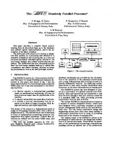
WINDCHIME ARCHITECTURE Windchime is really a framework for assembling a variety of MIMD message-passing parallel machines. At the heart of Windchime is a mesh-connected array of wormhole routing circuits. These circuits are the medium through which the Chime processors communicate. The Windchime routers are self-timed micropipeline circuits that communicate using the two-phase bundled protocol described above. Chimes communicate to the routers through the same twophase bundled interface. The Chimes are attached to the routing array by connecting a ribbon cable from the Chime processor to one of the headers on the router board associated with each routing node. In this way different parallel machines may be assembled by plugging a different set of Chimes into the router mesh. This organization is shown in Figure 3. Because the communication protocol used throughout Windchime is self-timed, the physical extent of the machine may be increased simply by attaching more routers and more processors. There is no concern with tuning the global clock to account for the additional hardware as there is no global synchronization, other than a global master reset signal. As long as the Chimes also conform to this protocol, they may be designed independently and connected to Windchime with assurance that the ensemble will continue to function correctly. If higher performance is required, the circuits that make up Windchime may be built from faster technologies. In fact, there is no restriction that each part of Windchime be constructed from the same technology. A fast CMOS chime, for example, can function without problems in the same machine that contains FPGA-based Chimes that operate at much lower speeds. Self-timed wormhole routing The Windchime router is a self-timed wormhole router inspired by the Torus Routing Chip (Dally 1986). Our router is connected in a mesh with each node having a pair of unidirectional bundled data channels in each routing direction and a pair of unidirectional bundled channels
6
Windchime: An FPGA-based Self-Timed Parallel Processor
+Xout
-Xin
+Yout
-Yin
Processor
Processor �
In
�
X-router
Y-router
Out
Windchime Router +Xin
-Xout
+Yin
-Yout
Figure 4 Windchime Router Circuit
X-offset
Y-offset
Signed Bytes (Two‘s Comp.) �
Length Unsigned Byte
Data Data
Data Bytes
Figure 5 Windchime Packet Format that connect to a Chime processor. Each node of this router is actually implemented as a pair of router circuits as shown in Figure 4. Each of this pair of circuits is built on a separate Actel 1020A FPGA and implements three data paths of the complete router: the first contains the input channel from the processor and the X-dimension channels, while the second implements the Y-dimension channels and the processor output channel. Each of these chips is the same design with a mode pin determining if the chip is an X-router or Y-router. Messages are injected into the routing network from the processor and are routed first in the X-dimension and then in the Y-dimension based on address information in the header of the packet until the message reaches its destination. At that point, the message is passed to the attached Chimes processor. All bundled data paths of the routers are 8 bits wide. The packet format for messages passed through the routers is shown in Figure 5. The first byte in the packet is the X-dimension offset, and the second is the Y-dimension offset. These offsets are signed (two’s complement) 8-bit quantities allowing offsets from -128 to +127 in each dimension. At each router in the message path the offset is updated. After the correct number of steps in the X direction, the offset has been updated to 0 and the message switches to the Y dimension. When the Y offset is 0, the message has reached its destination and is routed to the processor channel. As each offset reaches 0 it is consumed by the router so that the Chime does not receive the 0 offset bytes. The third byte in each packet is a length byte. This byte lets the router, and the eventual Chime recipient, know how many data bytes are contained in the packet. The wormhole routing used by the Windchime router will pass the entire message through the same path once the head of the packet, containing the offset information, has set the path through the array. The packet that is eventually delivered to the target Chime starts with this length byte and is followed by that number, from 0 to 255, of data bytes.
E. Brunvand
Processor In
ChanA
�
Positive In
Negative In
ChanB
A r b i t e r
Processor Out
M U X
ChanA
ChanB
D E M U X
Positive Out
Negative Out
ChanC Input Channels
7
Output Channels
Figure 6 Internal Block Diagram of a Router Chip The X-router and Y-router that make up one Windchime router each use an Actel 1020A FPGA. These circuits use 545 of the available 547 basic modules on the A1020 for 99% utilization of the Actel part. Such high utilizations are not usually possible for synchronous hardware. One reason is the limitation on the number of long wires in the FPGA. On the Actel array, for example, long vertical or long horizontal tracks are often the limiting resource in large designs. Because the self-timed organization of these circuits tend to use local connections, we have found that high utilization of FPGAs devices is often possible. On the other hand, the increased overhead of the self-timed circuits often makes high utilization necessary. Because of the limitations on the size of the A1020, each router chip has three input channels, but only two output channels that are shared between the three possible outputs as shown in Figure 6. Messages traveling in the negative direction always use the A output channel, and messages traveling in the positive direction always use the B channel. The channel from the processor can use either the A or B output channel (depending on the direction specified in the header) with the arbiter managing this overlap to make sure there are no collisions. The output circuit for the router chip has only two data paths, but three control paths so that although only two messages may be passing through the router at any time, they may use any combination of the three possible outputs. With an FPGA of larger capacity, three independent channels would have been possible. The current version of the Windchime routing board contains a three by three array of routers assembled using wire-wrap. There are headers for nine possible Chimes, and headers at the edges of the router array for connections to additional routers, peripherals, or to a host processor.
System interconnection In order for the Chime processor to connect to the Windchime routers they must communicate using an 8-bit two-phase bundled data channel and they must obey the packet protocol shown in Figure 5. In order to operate effectively in this environment, they should also have some additional features related to the Windchime system as a whole. One desirable feature is, at the risk of using confusing terms, to be able to synchronize with the other processors in the array. That is, many parallel algorithms synchronize at the software level by requiring that certain calculations have been completed by each processor in the ensemble before moving on to the
8
Windchime: An FPGA-based Self-Timed Parallel Processor
next phase of the computation. This is accomplished on Windchime by having each Chime processor implement a SYNC instruction. The effect of this instruction is to issue a transition on a special SyncReq line on the cable that connects the Chime to the router. Only when all the machines in the array have also issued a SYNC instruction, and thereby have sent a transition on their own SyncReq lines is a SyncAck issued to each processor. The Chimes will halt after issuing a SyncReq and not resume operation until they they have received a SyncAck. In this way the application running on Windchime can synchronize the processes that are running on individual Chimes. The current synchronization mechanism is a large C-element on the router board that collects the SyncReq transitions from each Chime and issues a single SyncAck to the entire array when they have all been seen. The cables that connect the Chimes to the router have a special pin that is pulled low when a processor is connected to that router. In this way the synchronizing C-element on the router is automatically aware of which Chimes are connected to the array and thus from which Chimes to expect SyncReq signals. Future versions of Windchime may have more complex synchronization primitives that would allow individual partitions of the current Chimes participate in the synchronization. The current version requires that all Chimes SYNC before any Chime can continue. Another potential problem with a parallel machine such as this is the possibility of deadlock in the router network. The Windchime routing algorithm can be made deadlock-free because the routers are able to route in both the positive and negative direction and thus cycles can be avoided. This does not mean, however, that deadlock cannot occur because of poorly written software. If a message is being sent to Chime A from Chime B, for example, but Chime A is not accepting it because it is busily trying to send a message back to Chime B, the system can deadlock as each Chime waits for the other to accept its message before continuing. To provide a means for avoiding this problem in software the Chimes are encouraged to implement PROBE instructions that operate on their router I/O channels. This PROBE is similar to that discussed by Martin (1985) and returns true only if the channel is capable of responding. That is, executing a PROBE instruction on an output channel will return true if sending a byte to that channel will succeed, and executing a PROBE on an input channel will return true only if there are data waiting to be accepted at that input channel. Since the software can use these PROBEs to decide whether an I/O action will succeed if attempted, software may be written that can avoid the type of deadlock mentioned above. Finally, the Windchime array should have a connection to the outside world, and have some means of initialization. This is handled through an attached host processor, currently a PC. The PC has an interface card that allows the PC to send and receive using two-phase bundled channels. These channels are connected to the Windchime router at the edge of the router board. This allows messages to be sent to any Chime in the array from the PC, and allows any Chime to send messages to the PC through the Windchime Router. This mechanism is also used for initialization. Each Chime has a “boot mode” that it enters after a reset signal. In boot mode the Chime expects to receive one packet through its router interface and deposit the contents of that packet into its memory. After receiving this single packet (which can contain up to 255 bytes) the Chime will issue a SYNC instruction to make sure that it does not begin operating until all the Chimes in the array have been similarly initialized. After receiving a SyncAck signal, the Chime will begin executing at the location where the boot packet was loaded. These boot packets are injected into the Windchime routing network, and thus to the individual Chimes, by the host PC.
E. Brunvand
9
SELF-TIMED CHIME PROCESSORS The Chime processors that are connected to make the Windchime machine can be of whatever design is useful, as long as they obey the restrictions mentioned previously. In fact, there is no reason the processors cannot be standard synchronous processors that implement the correct protocols at their interface. In practice, the Chimes currently developed for Windchime are themselves self-timed processors designed in the micropipeline style and acting without a clock signal. Due to space limitations, this section will present a brief description of only one type of Chime. Other Chimes include stack-based processors, standard accumulator based processors, a microcoded chime that shares its memory between microcode that implements a virtual machine of any size and the program code for that machine, a special-purpose Chime that sorts and merges input packets and then sends them back to the caller, and an arithmetic co-processor Chime that implements multiplication and division. Any of these Chimes may be plugged into the router board to configure a Windchime machine that is tailored to a particular application. The B-Minor Chime The B-Minor Chime is an 8-bit stack-based computer modeled after the Transputer. The register set of this Chime is shown in Figure 7 and include a three-deep evaluation stack, program counter, index register, and operation register (Op). The byte-wide instruction set of the B-minor Chime is also modeled after the Transputer. The instruction set is shown in Figure 8. As seen in the figure, instructions to the B-minor Chime are all single bytes. Of these bytes, the high four bits are an opcode, and the low four bits are a four-bit data value. This value is OR’d into the Op register before the instruction is executed. The PREFIX and LDOP instructions allow constants larger than four bits to be built in the Op register for later instructions. A consequence of this is that the Op register is cleared after each instruction is executed except for PREFIX and LDOP which leave the value in the Op register for the following instruction. As an example of using the PREFIX feature of this instruction set, consider adding the constant 0h19 (decimal 25) to the value currently in the stack. The sequence of instructions would be: PREFIX 0001 ADDI 1001 This would first put 0001 into the Op register, then shift it four places to the left. The ADDI instruction then OR’s the 1001 into Op, resulting in the 0h19 constant in the Op register which is then added to the value in the top of the stack. The arithmetic instructions all operate on the stack with A being the head of the stack and C being the tail. The arithmetic operation are examples of “operate” instructions. That is, the opcode bits of these instructions inform the processor to execute as if the Op register contains the opcode instead of the instruction register. This expands the instruction set from the 16 possible instructions to 31 instructions (with more possible in the future by building instructions in the Op register larger than 4 bits). Because of space limitations on the Actel 1020, the data path of the B-minor chime is 8 bits wide and the address space is 12 bits. Thus, for saving the PC and the Index register, two values must be pushed onto the stack. At this writing the datapath for the B-minor Chime has been
10
Windchime: An FPGA-based Self-Timed Parallel Processor
{
8-bits
{
12-bits
C
Op
B Index
A
PC
}
12-bits
ALU Temp
Inst
}8-bits
Figure 7 Register Set for the B-Minor Chime Mnemonic PREFIX LDOP LDI LD ST PUSHPC PUSHX ADJ ROUT RIN PIN POUT BRABS BRREL SYNC ADDI EQI ADD ADDC SUB COMP AND OR XOR NOT SHL SHRA SHRL EQ LT LE POP DUP
Encoding 1100 value 1101 value 1010 value 0110 value 0111 value 1111 value 1110 value 0010 value 1001 0000 1001 0001 1011 0000 1011 0001 0000 value 0001 value 1000 xxxx 0011 value 0100 value 0101 1100 0101 1101 0101 1111 0101 0110 0101 0000 0101 0001 0101 0011 0101 0010 0101 0100 0101 0101 0101 0111 0101 1000 0101 1001 0101 1011 0101 1110 0101 1010
Action Op value 1)(arithmetic), Pop, Push(Temp) Temp (A >> 1)(logical), Pop, Push(Temp) Push(A == B) Push(B < A) Push(B