WireFab: Mix-Dimensional Modeling and Fabrication for 3D Mesh Models Min Liu∗, 1 Yunbo Zhang∗, 3 Jing Bai, 1 Yuanzhi Cao, 1 Jeffrey M. Alperovich, 1,2 Karthik Ramani 1 School of Mechanical Engineering, Purdue University, West Lafayette, IN 47907 USA 2 School of Electrical and Computer Engineering†, Purdue University, West Lafayette, IN 47907 USA 1
{liu66, zhan2014, cao158, jal per, ramani} @purdue.edu 3
School of Computer Science and Engineering, Beifang University of Nationalities, Yinchuan, China bai
[email protected]
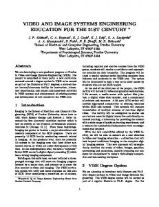
Figure 1. The building pipeline using WireFab: Given a 3D mesh Gringotts Dragon model, WireFab allows the user to (a) generate a smooth 1D inner skeleton and (b) customize the segmentations at the locations where the inner skeleton and the part are desired to be articulated, and (c) specify the corresponding rigid body appearances of different dimensionalities, joint types and motion ranges. Also the fabrication files of all appearances and joints are generated for the user to (d) quickly prototype and (e) assemble and pose the articulated character (fabricated Gringotts Dragon with 78 parts in total).
ABSTRACT
Many rapid fabrication technologies are directed towards layer wise printing or laser based prototyping. We propose WireFab, a rapid modeling and prototyping system that uses bent metal wires as the structure framework. WireFab approximates both the skeletal articulation and the skin appearance of the corresponding virtual skin meshes, and it allows users to personalize the designs by (1) specifying joint positions and part segmentations, (2) defining joint types and motion ranges to build a wire-based skeletal model, and (3) abstracting the segmented meshes into mixed-dimensional appearance patterns or attachments. The WireFab is designed to allow the user to choose how to best preserve the fidelity of the topological structure and articulation motion while selectively maintaining the fidelity of the geometric appearance. Compared to 3D-printing based highfidelity fabrication systems, WireFab increases prototyping * Min Liu and † By courtesy
Yunbo Zhang contributed equally to this paper.
Permission to make digital or hard copies of all or part of this work for personal or classroom use is granted without fee provided that copies are not made or distributed for profit or commercial advantage and that copies bear this notice and the full citation on the first page. Copyrights for components of this work owned by others than ACM must be honored. Abstracting with credit is permitted. To copy otherwise, or republish, to post on servers or to redistribute to lists, requires prior specific permission and/or a fee. Request permissions from
[email protected]. CHI 2017, May 06–11, 2017, Denver, CO. USA Copyright © 2017 ACM ISBN 978-1-4503-4655-9/17/05$15.00. DOI: http://dx.doi.org/10.1145/3025453.3025619
speed by ignoring unnecessary geometric details while preserving structural integrity and articulation motion. In addition, other rapid or low-fidelity fabrication systems produce only static models, while WireFab produces posable articulated models and has the potential to enable personalized functional products larger than the machines that produce them. ACM Classification Keywords
H.5.2. [Information Interfaces and Presentation]: User Interface Author Keywords
Mix-dimensional fabrication; shape abstraction; interactive curve modeling; skeletal deformation, physical prototyping INTRODUCTION
In recent years, personal design and fabrication have been enabled by the development of both hardware and software. People tend to design and fabricate 3D models based on their own ideas and in a variety of forms, such as origami, planar cross-section assembly, or 3D printing. The increasing popularity of 3D modeling software and personal fabrication devices has fueled a flurry of recent research towards seamlessly merging functional design and personal fabrication [23]. While tools and services that map static properties of a designed model to fabrication exist, constructing posable articulated models remains a difficult problem. Recent works [3, 7, 35] are proposed to tackle this issue using 3D printed parts
and joints. In this paper, we propose WireFab, a new system that supports wire-based multi-dimensional modeling and rapid fabrication for articulated models. WireFab utilizes the popular personal fabrication technologies such as 3D printing, and 2D laser cutting, and integrates them with newly available desktop wire bending technology [18]. Several geometric algorithms and corresponding interaction operations have been developed to enable the embedding of 3D static meshes with wire-based custom articulation, versatile appearance attachments and parameterized joints and connectors, leading to a flexible design and prototyping system for articulated models. We aim to lower the barriers to both design and fabrication so that designers who lack specialized knowledge can quickly prototype posable objects. To this end, we propose an intuitive workflow that takes as input a static 3D mesh model (see Fig. 1(a)) which could either be downloaded from online design repositories (e.g., http://www.thingiverse.com) or created using scanning systems such as Kinnect Fusion or Autodesk 123D Catch. The user designs an articulation model from the static mesh by first abstracting a smooth curve inner skeleton (Fig. 1(a)) that represents its skeletal structure. Using the inner skeleton as the rig, the input mesh is segmented by users at points where they desire individual parts and skeletons to be articulated (Fig. 1(b)). Users’ design intent is further realized by allowing them to interactively specify the corresponding rotational joint motion constraints, as well as the appearance of the segmented parts. WireFab allows users to balance fidelity and speed to best preserve the topological structure while selectively maintaining the fidelity of the geometric appearance by combining auto-generated 3D printable joints, 1D bendable skeletal wires, and user designed appearance attachments of various forms (see Fig. 1 (c)). This framework enables users to achieve the desired prototyping speed, kinematic motion, and aesthetic outlook of 3D models. RELATED WORK
We broadly classify the related work into functional design and fabrication, mixed 3D fabrication, fabrication-aware shape design, and articulated object modeling and fabrication. Functional design and fabrication: One of the trends we notice in the recent work on personal design and fabrication is the introduction of functionality into the fabrication process in order to allow non-expert users to create functional objects. Tubes and cuboids are embedded into given sculptural 3D models to house functionality and articulation in [29, 11] and are fabricated by low cost 3D printing processes. Prévost et al. [28] proposed an approach to generating models which can stand alone by deforming the initial inputs, while Spin-it [4] converts a given 3D model into a spinnable toy. Umentani et al. [34] proposed a method to deal with the flyability of laser cut paper airplanes. Other interesting works involve building working prototypes of mechanical designs for testing [16], printing mechanical toys [40] and characters with designable motions [33]. Most of these methods are based on 3D printing and suffer from the problems of slow processing time and extra post processing for support structures. The scale of objects generated by 3D printing is also constrained by the size of the printer.
Mixed 3D fabrication: Some recent works from the humancomputer interaction community have begun to explore the use of other fabrication methods together with 3D printing. By introducing intermediate low-fidelity fabrication into the traditional slow but high-fidelity 3D printing process, Mueller et al. and Beyer et al. proposed a variety of alternative fabrication methods to speed-up 3D printing, such as printing a wireframe mesh of an object [25], and substituting sub-volumes of a model with standard Lego building blocks [26] or laser-cut Platener [5]. Recent work CofiFab [32] combines 3D printing and 2D laser cutting to support the fabrication of large 3D objects, while WrapIt [14] generates 3D printed support structure to help users bend the wire into appropriate shape for jewelry making. These different approaches effectively reduced the fabricating time while preserving the shape of a static model, but none of them dealt with articulation deformations of posable objects. Fabrication-aware shape design: Lau et al. [19] presented a formal grammar combined with lexical and structural analysis to generate fabricatable parts and connectors from a 3D furniture model. Another study focuses on the constraints and sequences of assemblies by creating geometric puzzles, such as Polyomino [22] and Burr puzzles [37]. Li et al. [20] developed an algorithm for computing paper architecture using pop-ups. Megaro et al. [24] and Coros et al. [9] proposed interactive systems for designing animated mechanical characters. A recent work AutoConnect [17] generates connectors between different objects based on their shapes at connection points. Our WireFab is the first attempt, to the best of our knowledge, to focus on the automatic generation of both 3D-printed static connectors and motion joints specifically designed for wire connections and wire-based articulation. Articulated object modeling and fabrication Recent work on mapping 3D meshes to 3D-printable, jointed models either assumes that the input mesh is associated with linear blend skinning (LBS) [3], or manually inserts a classical animation rig into the input mesh [7]. However, the skinning weights or the animation rigs might not be directly available to naive users. The proposed WireFab takes advantage of recent advances in automatic curve skeleton abstraction, and interactive mesh segmentation to further simplify the process of creating ready-to-articulate and ready-to-fabricate 3D models with 3D static mesh input. In a related work, CarboardiZer [38] also takes a 3D static mesh as the input, but it focuses on generating planar foldable patterns for each rigid body and the joint type is restricted to a 1DOF (degree of freedom) hinge joint. In WireFab, the segmented rigid bodies may have different appearances, and it supports many joint types: 1D hinge, 2D universal, or 3D ball-and-socket joints. These joints enable more articulation functionalities in the design and fabrication space. Observing existing tools for the fabrication of articulated objects, it becomes apparent that most of them only allow for the fabrication of static models, though, some of them support articulated objects using 3D printing [3, 7] or 2D die cutting [38]. They are further limited by the size of the fabrication ma-
chines, the printing speed, or the types of motion achievable. The main contributions of WireFab are: 1) A new work-flow based on bent metal wires where inner skeletons of 3D models serve as the structural framework to which the appearances are attached;
the implementation, the medial geodesic function [10] based 1D curve skeleton was used as it is topology-preserving and stable against small changes.
2) 3D printed joint and connector primitives are automatically generated and are parameterized based on posability calculations with minimal user input; and 3) Multi-form appearance modeling and fabrication, including 3D printed detailed parts, 2D laser-cut planar cross-sections and 1D bent wires, which allows for a rich expressiveness. OVERVIEW
WireFab produces customizable articulated prototypes directly from digital 3D models. As shown in Fig. 2 , our computational design platform work-flow unfolds as follows: the designer (1) inputs a desired 3D mesh model, (2) edits the automatically generated inner curve skeleton to the desired structure and shape, (3) customizes the segmented parts and inner skeleton joint placement within the model to be articulated, (4) interactively designs the appearance of each part using a 3D solid object, 2D cross sections, or 1D wires, and (5) interactively designs the joint types, motion axes and motion ranges which define the articulation properties. The system then generates all the connectors, joints and appearances according to the fabrication model. Users are able to express their creativity and intent by controlling the number of articulated parts, appearance details, and the complexity of the articulation motion.
Figure 2. Pipeline process of WireFab.
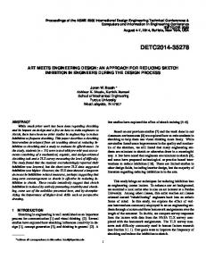
Figure 3. Some examples of skeleton editing tools and the final skeleton of the Gringotts Dragon model: (a) merging all skeletons between two junction points into one skeleton, (b) smoothing a skeleton, (c) deleting boundary segments, (d) final skeleton after editing with provided tools.
The inner curve skeleton is related but does not directly correspond to the rig required in articulation modeling; hence there is a need for editing curve skeletons to represent articulation rigs according to users’ intent. The edit operation is usually required when 3D models are noisy and complex with small features, the extracted skeleton may appear zig-zag and contain numerous small branches. Some skeleton details represent tiny topological structure variations but do not affect the overall articulation. Accordingly, we developed a set of interactive tools for users to generate smooth and compact skeleton-based rig, functions including merging multiple skeletons into one using the shortest curve path; deleting boundary skeletons according to the depths of connected junction points; and smoothing skeletons via linear, conic or cubic smoothing functions. Fig. 3 gives some examples of the editing capabilities and the final skeleton for the Gringotts Dragon model. Customizable segmentation for rigid parts and joint placement
SKELETON DRIVEN ARTICULATION MODELING
The articulated behavior of a posable object is modeled from a static mesh. A Skeleton is first extracted, edited and then the set of articulated joints are defined on it so that to separate the input model into joints and rigid bodies. Skeletal wire extraction and editing
WireFab assumes no animation rig associated with the input mesh and it starts by extracting 1D curve skeleton of every input 3D model to capture the structural information and support articulation motion. A digital curve skeleton have been computed by thinning from a volumetric model [31] or guided by a force field [8]. Geometric methods also exist for automatic skeletonization from surface meshes, which include mesh contraction [2], computing the Reeb graph [27], or surface inflation [30]. In order not to restrict our WireFab framework, we remain agnostic as to which skeletonization method is used. In
In WireFab, we adapt “dot scissor” [39] to capture local concave shape features using concavity-aware harmonic fields, and to select the best cutting boundaries using a voting scheme. The designer first specifies a stroke on the model surface (rendered as a small circle with the stroke as the diameter) through which the partitioning curves are expected to pass. The view direction vector and the stroke give a cutting plane which first creates a potential joint placement position on the inner skeleton. A concavity-aware harmonic field is then computed by using the user’s specified stroke as a constraint. A set of candidate curves are computed upon the harmonic field by extracting iso-value curves. The voting scheme as [39] is adapted to select the best partitioning curves according to their concavity, tightness, and proximity to the potential joint on the inner skeleton. The last term is measured as the average distance of the potential joint position c to k sampled points p1 , p2 , · · · , pk -on an iso-value curve. Our system with single stroke rather
than dots representation, allows more of the user intent to be captured by the design process than the “dot scissor" approach. If required, the user can undo this step, redraw the stroke, and re-run the segmentation, and the user has meanwhile an option of repositioning a potential joint along the inner curve skeleton. Joint specification
It is not possible to estimate automatically joint types, ranges and motion axes from a character’s skin model since the required explicit user inputs. Therefore, for each potential joint generated during skeleton segmentation, we give the user options to specify its articulation joint type, the corresponding rotation axes and their motion ranges. Three revolute joint types are supported in WireFab, which are: 3-DOF (degrees of freedom) ball-and-socket joints, 2-DOF universal joints and 1-DOF hinge joints as shown in Fig. 4. Ball-and-socket joints associate a cone axis vector nb and a socket opening angle θb as their motion range parameters. These joints span a wide range of angles and allow for intuitive free-form constraints on rotations away from the center axis (or cone axis) by shaping the socket opening. Universal joints associate two rotational axes (nu1 , nu2 ) and block in-axis rotation. Each rotational axis further associates two motion range parameters: forward swing angle θmax1 , θmax2 and backward swing angle θmin1 , θmin2 . Universal joints are common in the elbows and shoulders of characters but due to the difficulty in designing the gimbal lock configuration, this type of joint is seldom supported by previous work (see [3, 7, 38] ). In WireFab, the universal joint template is designed using the gimbal lock configuration with two rotational axes offset from each other by a small distance. This design frees a degree of restriction on the intersected rotational axes while also allowing for motion range restriction features incorporated into the design. Hinge joints have only one rotational axis nh and a motion range containing a forward swing angle and a backward swing angle (θmax , θmin ). In the joint templates developed in WireFab, both universal and hinge joints are coupled with a parametric motion range restriction feature which is automatically generated according to the users’ specifications on motion ranges. All motion axes are generated with their default directions based on the incident inner skeletons’ configuration. Specifically, a Frenet frame is calculated for each joint located on the inner curve skeleton, and this right-handed, orthogonal frame is used as the default joint frame for motion axis specification. Users are allowed to change the default motion axis and its default motion range using a simple widget-based joint specfication tool. APPEARANCE MODELING Solid appearance
A partitioned segment of the model can be represented as a solid part so that it can be 3D printed to retain the highest shape fidelity. The original segmentation results in a set of open surfaces, therefore a solid closure operation is applied to guarantee that all the segmented parts are water-tight and 3D printable. We adopted a dynamic programming based hole
Figure 4. Three types of revolute joints hinge, universal and ball-andsocket, from bottom to top, and their user specified joint parameters are illustrated in the right-hand column.
filling algorithm [21] as it is efficient and easy to implement. However, directly applying hole filling on the segment parts can be troublesome and not aesthetically appealing due to the irregular boundaries of the holes (see Fig. 5 (a)). Therefore, a geodesic curve stretching method [36] is applied to the original boundary curves of segments and the smoothed boundary curves are obtained after stretching (shown in Fig. 5 (b)). Consequently, the resultant solid model after hole filling has more aesthetic shapes with the smoothed boundary curves (see Fig. 5 (b)).
Figure 5. The boundary curves and resultant models before (a) and after (b) geodesic curve stretching.
Cross section and silhouette contours
Planar contours are the basic representation of an object’s shape as they contain explicit and dominant characteristics for determining an object’s appearance. We provide a planar section extraction tool in our platform to cut each partitioned rigid body with a set of cutting planes and obtain the resultant cross-sectional or silhouette contours. For cross-section contours, the user has the control either to cut a segmented part according to the tangential directions of the inner skeleton (normal-to-spine option), or to use a constant normal direction. To generate the initial cutting plane direction for constant normal cutting planes, the system applies principal component analysis (PCA) to the segment so that the cutting planes are created by taking the principal axis as the normal. Initial constant cross sectional contours take the principle axis with the largest eigenvalue as the direction while silhouette wire
appearance takes the smallest one as the cutting plane normal. For the normal-to-spine type of cross-sections, we calculate the pair-wise projected graph distance (the length of projected edge onto the first principal axis) and pick the one with the longest distance as the main spine. Fig. 6 gives an example of different planar contours generated automatically for user to use as appearance embodiment. For open contours, users are given the options to close them according to the solid closure or to manipulate the connection or closeness interactively.
the inner skeleton wire to ensure connectedness. If the helix wire is to be located at the bottom of a model, a flat end can also be added to the appearance to increase the stability of the structure, as shown in the example given in Fig. 7.
Figure 7. Helix wire is generated from cross section contours through arc length parametrization, neighboring contour alignment and point shifting.
Free-hand-draw wires
Figure 6. The planar contour tools that allow users to generate different 2D appearance patterns: (a) normal-to-spine cross section contours, (b) constant normal cross section contours with cutting planes normal to the first principal axis of a segment, and (c) silhouette contour with cutting plane normal to the last principal axis of a segment.
If the initial cutting plane setting is not satisfactory, a widget tool can be used to manipulate the cutting plane direction, offset the distances, or both, until it represents the desired cutting direction and offset. Furthermore, a snap fit pattern is added to each cross section plate so that it can be assembled and fit onto the skeletal wire. And silhouette contours adjust itself and intersect with the inner skeleton so that the connectedness is satisfied.
For users who have patience and hand dexterity, WireFab’s free-hand-draw module enables the user to define complex wire patterns on the object’s surfaces. We developed a set of interactive tools including curve creation, editing and clipping. Fig. 8 shows a curve editing tool which allows the user to modify the existing curve’s shape by dragging control points on the curve. During the whole process of curve creation and editing, all the points are snapped continuously onto the surfaces of a 3D model to make sure the curves perfectly follow the input model’s shape. The snapping of points onto surface is done by querying the closest point on the surface of input model for each point on the curve. This query can be done efficiently by adopting a bounding volume hierarchy structure on the input model.
Helix wires
Helix wire presents a segment portion of the object using 1D appearance and the least number of wire pieces; it contains only one continuous curve without self-intersection and it represents shape appearance information in a very compact way. Helix wire is computed based on the cross section contours. First, the set of cross section contours is analyzed for intersection if they were generated as normal-to-spine option. The intersecting sections will be removed from the set before they are referenced in the helix computation. Constant normal cross-sectional contours do not need to go through intersection testing as they are always parallel to each other. All the non-intersecting cross sections are then parameterized, from aligned starting points, using the arc length to the total contour length ratio as the parameter t (see Fig. 7 for example). The starting point of the parametrization is located at the intersection point of a planar contour and a silhouette contour. The points on the ith section are moved towards the corresponding points on the (i + 1)th section with the same arc length ratio t. When t changes from 0 to 1, the helix wire of one coil is formed in between the ith and the (i + 1)th sections. The helix wire is connected at one or both ends to the nearest point on
Figure 8. Curve creating and editing tools allow on-the-surface operations.
A design is composed of many curves and most of them are connected to each other, but the curve drawing and editing tool creates and edits a single curve individually without considering the interference between the curves. An interactive clipping tool is developed for the user to remove certain portion of the curve split by intersections with other curves. JOINT PARAMETRIZATION FOR POSABILITY
In the WireFab work-flow, all joints and connectors are designed to be 3D printed parts. One functional requirement for fabricated models is that the printed joints have to be tight enough to resist gravity and allow for static poses in the whole
articulation motion space. Adding friction to the contacting elements of joints is the most common way to achieve posability for articulated models. The friction can be introduced using bump features [3], tolerances [7], or locking fasteners [15]. Among these methods, bump features are less suitable for our purposes as they are susceptible to wear and tear due to the small feature size and the constraints of the plastic material used in most desktop 3D printing processes. Locking fasteners is the safest way to obtain the desired friction but they require extra parts, extra processing, or assembling time, and a more complicated joint shape. We therefore use the tolerance method, which enables a very compact design to obtain the desired friction force and to hold all static poses. Calibration The tolerance-based friction methods use interference fit between shafts and holes (or ball and socket in terms of ball-and-socket joint) to withstand the torques. Given any joint with its type and motion range specification, tolerances and dimensions have to be chosen to provide the desired degree of friction or torque. In theory, these joint parameters may be derived from known material properties, the specification of the 3D printing process, and the contact area of the joint. However, it is observed that even the same process may lead to different results and individual printers may vary. Thus, we leave the determination of joint dimensions and tolerances to a calibration process that we run on each printer before the joint synthesis. For this purpose, we created several data sets that are used for calibration by varying two different joint parameters: interference fit tolerance and joint diameter. For the 1DOF hinge and the 2DOF universal joint, the joint diameter is set as the inner diameter of the holes in contact with the standard size metal shaft. For 3DOF ball-and-socket joint, the joint diameter is set as the outer diameter of the ball part. By default, the joint shaft size is as same as the bent metal wire diameter and the shaft length is a dependent variable and is scaled in proportion to the shaft diameter. A calibration set example is given in Fig. 9. Based on the calibration test and theoretical torque calculation, the minimum size for a printable and functional joint can then be determined.
distance from the centroid of kth child segment to the motion axis of jth joint in its motion space. Of the three types of segment representation: 1D wire, 2D plate and 3D solid, the computation for the total volume of a child segment represented with wires and planar contour appearance is straightforward. Solid appearances are all represented as sets of triangular facets. It is a linear computation to calculate the interior volume of a mesh solid, done by summing the volumes of all the oriented pyramid centers at a point in 3D space (the origin, for instance) and taking a triangular facet for the base. The expression of the volume calculation of a meshed solid segment S is given in the following equation: VS =
1 |F| ∑ gk · Nk 6 k=1
(2)
where |F| is the number of triangles in S, gk = (xk1 +xk2 +xk3 )/3 and N = x~1 x2 × x~1 x3 . x1 , x2 and x3 are the three vertices of k
k k
k k
the kth triangular facet.
k
k
k
In the torque equation (1), the level arm distance from the centroid of the kth child segment to the motion axis of a joint varies with different poses in the articulation space. We estimate a maximum torque in the motion space by sampling the motion space of all child segments to find out the maximum level arm distance. With the required torque calculated, the joint size and tolerance parameters can then be chosen based on the calibration test. FABRICATION DETAILS
Snap fit design of 3D printed part to metal wire The basic connection of 3D printed parts (joints, connectors or solid appearances) to metal wire is shown in Fig. 10. A snap fit feature design is applied to all connections between metal wire and 3D printed parts. By default Dh will be a value smaller than the metal wire diameter for a tight fit or interference fit that prevents undesired movement. The user can redefine the tightness of the connection, then the diameter of the connection holder Dh will change accordingly.
Figure 9. Calibration sets for testing 3D printer parameters for achieving optimal friction. For this purpose we vary two parameters: tolerance and joint size. Note that the tolerance variation is not shown here since the interference value is too small to be visible.
Theoretical torque calculation The theoretical torque a joint needs to hold has to be calculated for each joint. It is the sum of all the torques generated by the gravities of all child segments of the focusing joint, and it can be calculated as follows: τ j = ∑ Vk ρk glk (1) where τ j is the desired torque that jth joint needs to hold, and Vk is the total volume of the kth child segment and ρk is its material density; lk is the corresponding maximum level arm
Figure 10. The geometric feature for a basic element, to connect 3D printed parts to metal wire. Dh is the inner diameter of the connector holder and it can affect the tightness of the fitting.
Wire-to-wire rigid connector We have classified three basic cases for rigid connectors that connect wire to wire with no motion. Case 1: Two or more wires intersect at one point (Fig. 11(a)); Case 2: One or more wires intersect at a point on another wire (Fig. 11(b)); and Case 3: Two or more wires are connected together in an envelope, but they do not necessarily
intersect at one point and need to be rigidly connected (Fig. 11(c)). The first two types of rigid connectors are generated automatically based on the wire configuration at junction points. The case three connectors, however, are defined through the user interaction.
Figure 11. Three types of rigid connectors.
Laser cut cross-sectional appearances One of the appearance options is to use laser cutting to acquire planar sheets that have the shape of the model’s cross-sections, and which snap fit onto the inner skeleton metal wire. WireFab has the ability to generate cross sections from the rigid parts and to apply the automatically generated snap-fit-to-wire pattern. Please refer to Fig. 12 for the cut-out pattern implemented in the current system. Each cross-section is assigned a sequence number that is included in the cutting pattern for identification during the assembly process. These patterns can then be sent to a laser cutter in DXF format to acquire the planar parts. A example DXF file for the Gringotts Dragon is shown partially in Fig. 12, where all ready-to-cut cross section plates with cut-out patterns are aligned inside the region corresponding to the sheet size specified by the user.
Figure 12. Left: Snap-fit-to-wire cutout pattern for a cross section contour of the Gringotts Dragon’s main body. Right: DXF file for the model (portion of the whole drawing is shown here due to the size limit). Dw is the metal wire diameter specified by the user, Ds is cut-out hole diameter, and there is a tight clearance (Dw − Ds )/2 designed for the snap fit functionality. A slot of width Ws which is incremented from Dw by a small amount is added to enable a smooth assembly of the metal wire with the laser cut sheet.
3D wire bending Pensa Labs [18] has a commercial desktop bender available that is capable of bending wires in 2D. While still available, the open source information regarding Pensa’s original 3D bender is now unsupported and has much left to be determined by the machine builder. The available information was taken and used to build a fully 3D wire bender to pair with WireFab (see Fig. 13 for the prototype). This bender is capable of bending any length of wire, and of straightening wires as they are fed through the machine. Its 3D wire
bending capability is implemented by adding an additional out-of-plane rotation onto the in-plane bending. It has bend angle and feed length limitations due to the constraints of the components, however, these limitations do not inhibit creating complex models. The bend limit is 90 degrees in-plane and the minimum wire feed length is 5mm. Our software system automatically enforces the feed length constraints and splits the wire where the turning angle exceeds the bending angle limit. To avoid collision, WireFab simulates bending toolpath, detects possible collisions, and splits wires into two at where collision is detected. For helix shapes shown in Fig.7, collisions between bending machine and helix wires can be avoided by setting a minimum pitch of the helix wire. The bender uses an Arduino to output commands to 3 step motors that control the feed, bend, and rotation about the z-axis. The commands are generated by WireFab in the form of a text file containing feed length, xy bend angle, and z bend angle. These commands are run through the processing software which couples to the Arduino, sending the appropriate signals to the 3D bender’s step motors.
Figure 13. The 3D desktop wire bender prototype built for WireFab.
Part labeling and assembly guidance Using WireFab’s interactive tools, users could generate quite complex designs. For example, the Gringotts Dragon shown in Fig. 1 has in total 78 parts including 3D printed parts, laser cut parts, and wire segments. To ease the effort of users, WireFab automatically adds numbers on the model of connectors and appearances, and these numbers can either be printed (3D printing) or carved (laser cutting) on the parts. Wires are bent in the order set by WireFab and labeled by attaching stickers on. The numbers are displayed around all parts and wires in the software when users assemble them. RESULTS AND DISCUSSION Prototypical results
We have first tested WireFab ourselves on a number of humanoid, animal and man-made 3D objects, and Fig. 14 demonstrates the design and fabrication results with some examples. Testing cases vary in complexity and include some sculptural models (e.g. dragon, giraffe and hand) and some real life objects (e.g. memento, glasses and helicopter), all downloaded from the internet. The glasses are modeled with two hinges and the appearances include solid, inner skeleton and silhouette wire. The memento is modeled as a static model with a helix appearance as it base. The giraffe has a bendable neck which is designed and fabricated with a series of 3DOF ball-and-socket joints. The hand model is fabricated with five universal joints and ten hinges, simulating the DOF of a real hand. The modeling for the helicopter involves a set
of freeform hand-draw curves, and all rigid connectors are generated automatically by WireFab. In the experiment, the joints, connectors and solid appearances are all printed using an EnvisionTEC Xtreme 3SP printer that has a resolution of 0.1mm along both the horizontal and the vertical directions. All planar cross sectional plates are fabricated with a CO2 golden laser cutter using acrylic sheets, and all metal wires are bent using our prototyped 3D wire bender, which supports three different wire diameters in the current implementation. All fabricated models are fully functional and easy to manipulate while maintaining a balanced level of friction to allow for posing. Fig. 15 shows the results for hand and giraffe models articulated in different poses. A common issue with 3D printed joints is their durability. Depending on the printing processes, continued manipulation of a joint can lead to reduced friction due to wear and tear. However, since one of the friction elements in our joint template for universal and hinge joints is a metal shaft, the issue is less serious compared with in the pure 3D printed ball-and-socket joints. Preliminary user study
In order to verify the usability and the expressiveness of our system, we have invited 12 users to participate in our user study. All of them were engineering college students and none of them had any prior experience of using our system. We divided all the participants randomly into 4 groups, 3 users for each group. All the users in the same group were given the same model to process. Each user’s study consisted of two sessions, the design session and the physical assembly session. During the first session, the users received a 10 minute tutorial on how to use our software. Then the users would be given a model to process with the software. Based on the users’ input, all the physical parts including the metal wires, joints and connectors, and acrylic cross-sections were fabricated for the second session. During the physical assembly session, the users also received a 10 minute tutorial about handling the physical parts before they started assembling. A virtual 3D model with all required assembly information (e.g. the labeling of wires, joints and connectors and their configuration in 3D space) is given to user as an instruction of assembly. And then the users would perform hands-on assembly to produce the prototype based on the virtual model they processed during the first session. The primary users’ prototyping results are shown in Fig. 16. The expressiveness of users using our system is demonstrated directly by the end results. We can observe a variety of different expressions designed by the users who started with the same model (please refer to Fig. 16). For group 1-3, we can observe the choice of different appearances as well as user-defined functional joints. For group 4, we intentionally tested a conical shape which is not a typical articulated shape. All users processed it successfully with a static model using hand-draw surface wire tool. The users came up with various artistic surface patterns that already transcend the original conical geometry. During the user study, every user was asked to fill out a questionnaire designed based on the system usability scale (SUS)
[6]. The primary survey results are given in Fig. 17. The average SUS score was 82 (SD - 9.64). Each user took the same questionnaire twice after both the design and assembly sessions and therefore a total of 24 survey results has been collected. In Fig. 17, we sorted the survey results separately for each session and plotted their SUS scores. We observe that the average SUS score after the first session (interactive design) was 79 (SD-9.07), while the average SUS score after the second session (hands-on assembly) increased to 85 (SD-9.59). Discussion
We benchmarked the efficiency of WireFab by comparing the total time using WireFab with the printing time using 3D printer (EnvisionTEC Xtreme 3SP) for the same set of tested models. There are three main parts where the users spend their time within the work-flow: (1) Interacting with the WireFab software, (2) waiting for physical parts to be fabricated by the authors. and (3) assembling the physical parts into the final prototypes. We have recorded the time spent on all the models demonstrated in our paper. In the time statistic, the fabrication time are included, but the overhead time for preparing the machines and operating associated software are excluded. To fit the size constraint of 3D printer, all tested models are scaled such that their largest dimensions are in the range of 200-300 mm. To 3D print any of those models would take more than 10 hours, while using our system, we spend less than 2 hours on any of the model except the model (3) in Fig.16 presented in the paper. It took around 4 hours for that model since the user chose to use solid appearance for the main body of the model. The overall fabrication time is greatly shortened compared to 3D printing the whole model. The users spend most of their time doing the interactive design and hands-on assembly, rather than waiting idly for the fabrication. The time it takes to advance an idea from the 3D model to the physical prototype which also includes all the articulation is better using the wire bending tools and methods we present here. Another divergence between 3D printing and WireFab is the fidelity of the products. The process developed using WireFab allows for a multitude of fidelity options, based on the user’s preferences for time and appearance. This mix of fidelity not only caters more closely to the user’s desires (whether it be for a time sensitive shape model or an appearance reliant structural element) but it is also able to match the fidelity of 3d printing. The mixed medium modeling capabilities of WireFab also serve to maintain and highlight the articulation of the joints, a feature that adds additional processing options that are outside the capabilities of the common user. But it is fair to point out that the shape fidelity is sacrificed in terms of build appearance if the user desires a full shape reproduction as designed. In addition the rigidity is replaced by an articulated model. For the usability of the proposed system, the above SUS scores indicated a good usability of our system, that within a total of less than 2 hours, the users could produce a new prototype that was very different from the model they started with. Besides quantitative evaluation using SUS scores, we also collected users’ qualitative feedback during and after user study. For the simplicity of notation, we label users according to
Figure 14. Prototypical results generated by WireFab. The first row from left to right shows input models for: Glasses, Memento, Giraffe, Hand and Helicopter and their initial segmentation with potential joints. The second row shows the appearances design using different forms and the corresponding virtual fabrication models which incorporate all connectors and joints. In the last row, all finished physical prototypes are shown (from left to right, each fabricated model consists of 12, 24, 56, 46, and 72 parts respectively.).
Figure 15. Photographs of hand and giraffe models articulated in different poses.
which model they designed and assembled (shown in Fig. 16 (1)-(12)). In general, users appreciated WireFab’s interactive tools to be “easy to learn and use” (user 12). User 2 found WireFab’s appearance modeling tools invaluable for better expressing their design intent: “it was easy for me to create the prototype as I expected.” As user 1 expressed, “(appearance modeling tools) were really interesting for me as I could see how the part was going to look like after assembled, depending on the choice of the manufacturing methods.” It is also
noted that most users chose to first go through all possible appearances in the WireFab and then made their decision based on their aesthetic preferences. User 1 particularly enjoyed WireFab’s customized segmentation and joint specification tools, as they “were the easiest tools to use for generating movable objects among all software (he used)”. WireFab’s joint parameterization greatly supported the generation of movable joints, as “(users) just specified the type of motion/degrees of freedom between 2 parts and the system automatically did the rest” (user 1). We also found that users tended to segment the model and put the joints based on their understanding of its semantic components and intent to articulate. Another important observation is that the tangibility of assembly greatly affects users’ experience. The SUS score in Fig. 17 shows a significant increasing before and after users’ hands-on assembly (79 with SD-9.07 vs. 85 with SD-9.59). The users were generally more satisfied with the system after the second session where they get to assemble the prototype themselves. We have observed great satisfaction among the users upon finishing assembling their models, many of the users were excited enough to take out their camera and took pictures of their models. They felt that they have actually created something new. The user who did model 7 in Fig. 16 said this after the second session : “I didn’t know it was going to be this cool when I did it on the computer.” Another user who did model 10 said: “I think this kind of hands-on practice is really helpful
dressed in the future by choosing stronger materials for joint fabrication. CONCLUSION AND FUTURE WORK
In this paper we present WireFab, a rapid design and prototyping system that allows makers to customize and articulate everyday sculptural models by extracting a skeletal wire, adding joints and attaching various appearances to segmented rigid parts. The computational design platform and prototyping pipeline are explicitly constructed to ensure a rapid design and digital fabrication system based on a semi-automatic process, limited interactive modeling and multiple personal fabrication tools. The mixed dimensionality of the system gives novice, as well as expert designers more flexibility towards modeling and prototyping posable models. Our primary results and users’ study show that our method can handle different types of input meshes in terms of geometrical complexity and variety and number of articulations.
Figure 16. Results from the user study. The first row shows the four testing models and the second to fourth rows show different articulation models built by different users. (a) Group 1 users were given a crane model to process (from top to bottom, the fabricated objects consists of 40, 23, and 16 parts). (b) Group 2 users were given a dragonfly model (from top to bottom, the fabricated objects consists of 24, 26, and 28 parts). (c) Group 3 users were given a air plane model (from top to bottom, the fabricated objects consists of 33, 21, and 12 parts). And (d), group 4 users were given a conical shaped model to process (from top to bottom, the fabricated objects consists of 63, 27, and 28 parts).
Figure 17. (a) Results of the SUS survey after the first session(b) Results of the SUS survey after the second session.
There are several remaining challenges which may direct our future work. Currently, our system relies on visual feedback for collision detection in the relative motion between two rigid parts. An automatic collision test and feedback will help users to make more feasible designs and achieve the desired articulation range in real world models. Reducing the number of wires makes fabricating some specific shapes very efficient with less number of connectors. Currently this decision is left to the users, but it is helpful if the users had some computational guidance. Structural stability analysis would further enhance the usability of the tool. Another expansion option is towards systematic electromechanical embedding strategies so that modular electronic components can be pre-assembled with the motion joints. To further enhance the value of WireFab, we could also extend it to large structures with 3D fortified metal joints. In this paper, the focus of WireFab is the new workflow of turning existing 3D models into articulated mixed-fidelity objects. Therefore, we constrained the capability of interactive shape design. The shapes of input models remain unchanged, but only the appearance of each segmented part can be customized during the whole process. We would like to further extend this work by exploring the shape design freedom in the future. ACKNOWLEDGMENTS
to promote motivation in learning.” The hands-on assembly helped users to “understand the software (of WireFab) from a perspective of hands-on activity” (user 5). This tells us just how important physical user interaction really is, especially in the personalized fabrication area. User constructed objects have been shown to promote self-extension into them and to be more engaging [13]. Prior studies [1, 13, 12] have indicated that the design, fabrication and assembly process is enjoyable and self actualizing, and computer supported creative design and fabrication processes requires further understanding as a means for engaging and embodied learning experiences. From users’ feedback, WireFab has several limitations. One user found it was difficult to assemble when “3 or more wires are connected to one connector” (user 12). Users also pointed out the joints “were a little weak and fragile" (user 5), thus “they were easy to break” (user 7). This problem could be ad-
We thank the reviewers for their valuable feedback. This work was partly supported by the National Science Foundation Award 1632154 IIP and 1329979 CPS. Jing Bai was supported by the National Natural Science Foundation of China (No. 61163016) and University Scientific Research Projects of Ningxia Province (NGY2015161). Any opinions, findings, and conclusions or recommendations expressed in this material are those of the author(s) and do not necessarily reflect the views of NSF. REFERENCES
1. Eric Almquist, John Senior, and Nicolas Bloch. 2016. The Elements of Value. Harvard Business Review (2016), 47–52. 2. Oscar Kin-Chung Au, Chiew-Lan Tai, Hung-Kuo Chu, Daniel Cohen-Or, and Tong-Yee Lee. 2008. Skeleton
extraction by mesh contraction. In ACM Trans. Graph., Vol. 27. 44. 3. Moritz Bächer, Bernd Bickel, Doug L. James, and Hanspeter Pfister. 2012. Fabricating Articulated Characters from Skinned Meshes. ACM Trans. Graph. 31, 4 (July 2012), 47:1–47:9. 4. Moritz Bächer, Emily Whiting, Bernd Bickel, and Olga Sorkine-Hornung. 2014. Spin-it: Optimizing moment of inertia for spinnable objects. ACM Transactions on Graphics (TOG) 33, 4 (2014), 96:1–96:10. 5. Dustin Beyer, Serafima Gurevich, Stefanie Mueller, Hsiang-Ting Chen, and Patrick Baudisch. 2015. Platener: Low-Fidelity Fabrication of 3D Objects by Substituting 3D Print with Laser-Cut Plates. In Proceedings of the SIGCHI Conference on Human Factors in Computing Systems (CHI ’15). ACM Press, 1799–1806. 6. John Brooke. 1996. SUS: A quick and dirty usability scale. (1996). 7. Jacques Calì, Dan A. Calian, Cristina Amati, Rebecca Kleinberger, Anthony Steed, Jan Kautz, and Tim Weyrich. 2012. 3D-printing of Non-assembly, Articulated Models. ACM Trans. Graph. 31, 6 (Nov. 2012), 130:1–130:8. 8. Jen-Hi Chuang, Chi-Hao Tsai, and Min-Chi Ko. 2000. Skeletonization of Three-Dimensional Object Using Generalized Potential Field. IEEE Trans. Pattern Anal. Mach. Intell. 22, 11 (Nov. 2000), 1241–1251. 9. Stelian Coros, Bernhard Thomaszewski, Gioacchino Noris, Shinjiro Sueda, Moira Forberg, Robert W. Sumner, Wojciech Matusik, and Bernd Bickel. 2013. Computational Design of Mechanical Characters. ACM Trans. Graph. 32, 4 (2013), 83:1–83:12.
15. Alec Jacobson, Daniele Panozzo, Oliver Glauser, Cédric Pradalier, Otmar Hilliges, and Olga Sorkine-Hornung. 2014. Tangible and Modular Input Device for Character Articulation. ACM Trans. Graph. 33, 4 (2014), 82:1–82:12. 16. Bongjin Koo, Wilmot Li, JiaXian Yao, Maneesh Agrawala, and Niloy J Mitra. 2014. Creating works-like prototypes of mechanical objects. ACM Trans. Graph. 33, 6 (2014), 217:1–217:9. 17. Yuki Koyama, Shinjiro Sueda, Emma Steinhardt, Takeo Igarashi, Ariel Shamir, and Wojciech Matusik. 2015. AutoConnect: Computational Design of 3D-printable Connectors. ACM Trans. Graph. 34, 6 (2015), 231:1–231:11. 18. Pensa Labs. 2016. DiWire-Pensa Labs. (2016). http://www.pensalabs.com/diwire-overview/.
19. Manfred Lau, Akira Ohgawara, Jun Mitani, and Takeo Igarashi. 2011. Converting 3D Furniture Models to Fabricatable Parts and Connectors. ACM Trans. Graph. 30, 4 (July 2011), 85:1–85:6. 20. Xian-Ying Li, Chao-Hui Shen, Shi-Sheng Huang, Tao Ju, and Shi-Min Hu. 2010. Popup: Automatic Paper Architectures from 3D Models. In ACM SIGGRAPH 2010 Papers (SIGGRAPH ’10). 111:1–111:9. 21. Peter Liepa. 2003. Filling Holes in Meshes. In Proceedings of the 2003 Eurographics (SGP ’03). 200–205. 22. Kui-Yip Lo, Chi-Wing Fu, and Hongwei Li. 2009. 3D Polyomino Puzzle. ACM Trans. Graph. 28, 5 (Dec. 2009), 157:1–157:8.
10. Tamal K. Dey and Jian Sun. 2006. Defining and Computing Curve-skeletons with Medial Geodesic Function. In Proceedings of the Fourth Eurographics Symposium on Geometry Processing (SGP ’06). 143–152.
23. James McCrae, Nobuyuki Umetani, and Karan Singh. 2014. FlatFitFab: Interactive Modeling with Planar Sections. In Proceedings of the 27th Annual ACM Symposium on User Interface Software and Technology (UIST ’14). 13–22.
11. Wei Gao, Yunbo Zhang, Diogo C. Nazzetta, Karthik Ramani, and Raymond J. Cipra. 2015. RevoMaker: Enabling Multi-directional and Functionally-embedded 3D Printing Using a Rotational Cuboidal Platform. In Proceedings of the 28th Annual ACM Symposium on User Interface Software & Technology (UIST ’15). 437–446.
24. Vittorio Megaro, Bernhard Thomaszewski, Damien Gauge, Eitan Grinspun, Stelian Coros, and Markus Gross. 2014. ChaCra: An Interactive Design System for Rapid Character Crafting. In ACM SIGGRAPH/Eurographics Symposium on Computer Animation (SCA’14). 123–130.
12. Victoria Groom, Leila Takayama, Paloma Ochi, and Clifford Nass. 2009. I am my robot: the impact of robot-building and robot form on operators. In Proceedings of the 4th ACM/IEEE international conference on Human robot interaction. ACM, 31–36.
25. Stefanie Mueller, Sangha Im, Serafima Gurevich, Alexander Teibrich, Lisa Pfisterer, François Guimbretière, and Patrick Baudisch. 2014a. WirePrint: 3D Printed Previews for Fast Prototyping. In Proceedings of the 27th Annual ACM Symposium on User Interface Software and Technology (UIST ’14). 273–280.
13. Imre Horváth. 2004. On some crucial issues of computer support of conceptual design. In Product Engineering. Springer, 123–142. 14. Emmanuel Iarussi, Wilmot Li, and Adrien Bousseau. 2015. WrapIt: Computer-assisted Crafting of Wire Wrapped Jewelry. ACM Trans. Graph. 34, 6 (2015), 221:1–221:8.
26. Stefanie Mueller, Tobias Mohr, Kerstin Guenther, Johannes Frohnhofen, Kai-Adrian Rollmann, and Patrick Baudisch. 2014b. faBrickation: Fast 3D Printing of Functional Objects by Integrating Construction Kit Building Blocks. In CHI ’14 Extended Abstracts on Human Factors in Computing Systems (CHI EA ’14). 527–530.
27. Valerio Pascucci, Giorgio Scorzelli, Peer-Timo Bremer, and Ajith Mascarenhas. 2007. Robust On-line Computation of Reeb Graphs: Simplicity and Speed. ACM Trans. Graph. 26, 3 (2007).
34. Nobuyuki Umetani, Yuki Koyama, Ryan Schmidt, and Takeo Igarashi. 2014. Pteromys: Interactive Design and Optimization of Free-formed Free-flight Model Airplanes. ACM Trans. Graph. 33, 4 (July 2014), 65:1–65:10.
28. Romain Prévost, Emily Whiting, Sylvain Lefebvre, and Olga Sorkine-Hornung. 2013. Make It Stand: Balancing Shapes for 3D Fabrication. ACM Trans. Graph. 32, 4 (July 2013), 81:1–81:10.
35. Francisca Gil Ureta, Chelsea Tymms, and Denis Zorin. 2016. Interactive Modeling of Mechanical Objects. In Computer Graphics Forum, Vol. 35. Wiley Online Library, 145–155.
29. Valkyrie Savage, Ryan Schmidt, Tovi Grossman, George Fitzmaurice, and Björn Hartmann. 2014. A Series of Tubes: Adding Interactivity to 3D Prints Using Internal Pipes. In Proceedings of the 27th Annual ACM Symposium on User Interface Software and Technology (UIST ’14). 3–12.
36. Charlie CL Wang. 2004. CyberTape: an interactive measurement tool on polyhedral surface. Computers & Graphics 28, 5 (2004), 731–745.
30. Andrei Sharf, Thomas Lewiner, Ariel Shamir, and Leif Kobbelt. 2007. On-the-fly curve-skeleton computation for 3D shapes. ACM Trans. Graph. 26, 3 (2007), 323–328. 31. André Sobiecki, Andrei Jalba, and Alexandru Telea. 2014. Comparison of curve and surface skeletonization methods for voxel shapes. Pattern Recognition Letters 47 (2014), 147–156. 32. Peng Song, Bailin Deng, Ziqi Wang, Zhichao Dong, Wei Li, Chi-Wing Fu, and Ligang Liu. 2016. CofiFab: Coarse-to-Fine Fabrication of Large 3D Objects. ACM Trans. Graph. 35, 4 (2016). 33. Bernhard Thomaszewski, Stelian Coros, Damien Gauge, Vittorio Megaro, Eitan Grinspun, and Markus Gross. 2014. Computational Design of Linkage-based Characters. ACM Trans. Graph. 33, 4 (2014), 64:1–64:9.
37. Shiqing Xin, Chi-Fu Lai, Chi-Wing Fu, Tien-Tsin Wong, Ying He, and Daniel Cohen-Or. 2011. Making Burr Puzzles from 3D Models. In ACM SIGGRAPH 2011 Papers (SIGGRAPH ’11). 97:1–97:8. 38. Yunbo Zhang, Wei Gao, Luis Paredes, and Karthik Ramani. 2016. CardBoardiZer: creatively customize, articulate and fold 3D Mesh Models. In Proceedings of the SIGCHI Conference on Human Factors in Computing Systems (CHI ’16). 897–907. 39. Youyi Zheng, Chiew-Lan Tai, and Oscar Kin-Chung Au. 2012. Dot scissor: a single-click interface for mesh segmentation. Visualization and Computer Graphics, IEEE Transactions on 18, 8 (2012), 1304–1312. 40. Lifeng Zhu, Weiwei Xu, John Snyder, Yang Liu, Guoping Wang, and Baining Guo. 2012. Motion-guided Mechanical Toy Modeling. ACM Trans. Graph. 31, 6 (Nov. 2012), 127:1–127:10.