Aug 17, 2009 - unmanned aerial vehicle (UAV) in a wireless relay communication system. ... advantage of using UAVs is that they can be quickly deployed.
Wireless Relay Communications using ann Unmanned Aerial Vehicle Pengcheng Zhan, Kai Yu, A. Lee Swindlehurst Department of Electrical and Computer Engineering,
Brigham Young University, Provo, UT, USA, 84602 Telephone: (801) 422-3930, Fax: (801) 422-0201 e-mail: {pz8,kaiyu,swindIe}jdee.byu.edu Abstract- Herein, we investigate the optimal deployment of an unmanned aerial vehicle (UAV) in a wireless relay communication system. The optimal UAV position is found by maximizing the average data rate, while at the same time keeping the symbol error rate (SER) below a certain threshold. We derive a closedform expression for the average data rate in a fixed wireless link using adaptive modulation. By using the alternate definite integral form for the Gaussian Q-function, the symbol error rate (SER) of the system in the link level is evaluated. An upper bound on the SER is also derived using the improved exponential bounds for the Q-function. It is shown that the derived SER expression matches the simulation results very well and the derived upper bound is tight for a wide range of SNRs. Simulation results also show that the system data rate matches the derived closed-form expression.
,....X
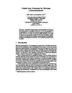
Fig. 1. Battlefield relay communication scenario
I. INTRODUCTION
Recently, unmanned aerial vehicles (UAVs) have attracted considerable attention in many military as well as civilian applications [1], [2]. Besides other advantages, one major advantage of using UAVs is that they can be quickly deployed into the battlefield, or various communication environments as relays [3], and therefore improve the performance of wireless communications systems [4], [5]. For example, in many communication scenarios, there exist obstacles (such as mountains, buildings, etc) that severely deteriorate or even block the signal between the transmitter and, the receiver. In such cases, one can deploy a UAV to help setup the communication link and improve the communication perfonnance, i.e. using the UAV as a relay between the transmitter and the receiver. In this paper, we assume there is no direct communication link between the transmitter and the receiver. A UAV is assumed to be positioned so that it can relay messages from the transmitter to the receiver, as depicted in Fig. 1. Assuming adaptive modulation is employed, in the communication system, we analyze the average data rate of the system, and investigate the optimal position of the UAV so that the transmission rate is maximized under the constraint that the symbol error rate (SER) is below a certain threshold. The paper is organized as follows. Section II presents the system model used in this paper In Section III we derive the closed-form expression of the average data rate, and formulate the optimization problem to find the optimal position of the
UAV. An SER analysis is also given in this section. Numerical simulation results are presented in Section IV, followed by some conclusions in Section V. II. SYSTEML MODEL
A. Two-hop half duplex protocal In this paper, we assume that a two-hop half-duplex protocol is used in the system. During the first time slot, the transmitter sends the desired message to the UAV. The UAV decodes the message and then sends it to the receiver in the second time slot. Note that we assurme the UAV can not transmit and receive simultaneously. Using the above transmission protocol, the signal model for the first and second time slots can be written as
Yi = X His, + nL,
(L
and
£2 (2) + N H2s2 n2, where Yi is the received signal at the UAV HI is the channel matrix between the transmitter and the UAV, s, is the Y2
=
/
transmitted signal, and nii is additive noise. Similar definitions are used in (2) except that in this time slot the UAV becomes the transmitter. We will let IM denote the number of antennas at ground stations, N the number of antennas at UAV, and we
Authorized licensed use limited to: IEEE Editors in Chief. Downloaded on August 17, 2009 at 20:00 from IEEE Xplore. Restrictions apply.
let E£., Es2 represent the transmission power during the two time slots. B. Channel model We assume the channels H1 and H2 are Rayleigh fading channels with large scale path loss, i.e. Hi= Hnor
(3)
i,l
D. Orthogonal space-time block coding We assume that in both time slots, only the receiver knows the channel matrix. Hence, orthogonal space-time block codes (OSTBC) [11] are used to transmit the data. For example, in the 2 x 2 case, the well-known Alamouti code [12] is employed. Since adaptive modulation is used, the receiver needs to determine/predict a suitable modulation scheme and feed this information back to the transmitter. In this paper, we assume that this feedback is perfect, i.e. the transmitter knows which modulation scheme to use. Note that feeding back the modulation scheme costs much less than feeding back the full channel state information.
where Hnorm is a normalized complex Gaussian channel which when stacked in an NMXI x 1 vector has the distribution CA (O, RH), and di,u is the distance between the ith access point (AP) {i = 1, 2} and the UAV. In our application, AP 1 is the transmitter and AP2 the receiver. For free space transmission, the path-loss exponent a equals one [6]. Values Ill. SYSTEM ANALYSIS of a > 1 occur in obstructed environments, while a < 1 is OSTBC exploits the diversity of the MIMO channels, and common in wave-guided environments. Note that log-normal the instantaneous uplink SNR at the UAV can be expressed as shadow fading can easily be included in the channel model and the analysis below. Assume the coordinates of the ith AP and FH1 ()2 UAV are given as [xi yi hi]TaTnd [xlt yu hu]T respectively, so that di, can be written as 2HllFP (7) 1
_A.Xi2 y ,2 h ,2 (4) We use the well known Kronecker approach [7], [8] to model the correlation matrix RH of the MIMO wireless channels, i.e., RH = RTX 0$ RRx, where RTX are RRx are respectively the normalized transmit and receive channel correlation matrices. If APl and AP2 are located in multipath scattering environments, we would see low spatial correlation at APL and AP2. At the UAV side, however, high spatial correlation is expected since there are few if any scatterers near the UAV. The normalized channel matrix is expressed as
di,u=
Hr = (RRx )'2G[(RTx) /2]T (5) where the stochastic V by MI matrix G contains independent and identically distributed (IID) C.A(0, 1) elements, (.)T denotes transpose, ( ) 1/2 is defined such that R1 /2 (Rl /2)H R, and (H) is the lHermitian transpose. C. Adaptive modulation We assume that the system employs adaptive modulation based on the current channel SNR, denoted by y. For a given desired SER, the required SNR thresholds are predetermined using the SER expression given in [9], [10]:
Pe N_ Q(
)
where p is defined as p = (oN is the noise power, and 2 11 lFdenotes the Frobenius norm. Plugging (3) into (7), we obtain Hnorm 2 (8) r
Fu
A similar analysis can be used to find the SNR of the downlink channel from the UAV, if we replace d1jU with d2,u and M with N. In [13], using the inverse Laplace transform, the probability density function (PDF) of lHrnorm ll2 is derived as
f (x)
p mj
=
j= 1k=
ki
1£Aj,-jk, (k
will be used to transmit the message. If y < 71, no transmit scheme will be chosen, which indicates there will be no transmission between the transmitter and. the receiver.
(9)
where o-j (j = 1 2, P) are the distinct non-zero eigenvalues of RH, and mj denotes the respective multiplicities of o-j. By solving a system of linear equations, Ajk can be determined [13]. By defining
g(Ti, a, X)
=
! axdx I ,ax
T01
n
0
(6)
wxhere P, is the cymbol error probability, N is the number of nearest neighbor constellation points, and dmi0r is the minimum separation distance between points on the underlying constellation. Assume that Yk and k+l are the predetermined SNR thresholds for the kth and (k + 11th modulation schemes respectively. If k+l > -Yk, the kth modulation scheme
u(x),
c
)
i
.
(1 0)
the cumulative distribution function (CDF) of urH,, F can be expressed as in (ll\) A Ergodic normalized transmission rate Due to the random nature of the channel matrices, the instantaneous transmission rate is different for different channel realizations. Therefore, we define the ergodic normalized transmission rate (ENTR) and. use it as the criteria to quantify the performance of the link. ENTR is defined in equations (12) and (13), (12) RiP 0 (t) = 3 (loE1 2 (t)
Authorized licensed use limited to: IEEE Editors in Chief. Downloaded on August 17, 2009 at 20:00 from IEEE Xplore. Restrictions apply.
F(x)
L
X
f (t)dt
=
E j=l k=
-oo
K(t)
Ri,u(t)
log2~ KiK) {log,2
i {E
=
1
0-i
0)I
(11)
(13)
(Ki+l-Ki)u(1(t)- i+l),
f(
J i (t)
i= L-1
g(k
0-i
i=
tCi+ (t)
L-1 =
[g(k
-'
pu(C(t)- y) (+
K
=
mj
:
( x)dx+ lo2KL J CF (t) f (x)dx}
E 1K924i[F (Ci+1 (t)) -F(Ci (t))] + 1 K92KL [1 -F(CL (t))] } *3{Z
(14)
i=l
where is a scalar that takes into account the rate loss when OSTBC is used. Note that for 2 x 2 Alamouti coding, = 1. In (113), Ki is the number of the constellation points for the ith modulation scheme, and L is the total number of modulation schemes used in the system. Defining Ci (t) = ]L d 2 (t), it is straightforward to show that the expression for the ETNR of the API-UAV link can be written as in (14). A similar expression can be obtained for the UAV-AP2 link. Since the communication between APL and AP2 is through the UAV relay, and, also due to the two-hop half-duplex characteristics of the communication system, the overall transmission rate is (15) R(t) = mint{R1, (t), R2,u,, (t) I In order to improve the system performance, i.e. to increase the overall network transmission rate R(t), we position the UAV according to the following optimization problem: arg max R(t) xtZ (t), Y".; (t), h.jL (t) U)
< PT
Pe 2, u) 0.
(18)
bix2
aiexp( E i=l