J. Sens. Sens. Syst., 3, 113–120, 2014 www.j-sens-sens-syst.net/3/113/2014/ doi:10.5194/jsss-3-113-2014 © Author(s) 2014. CC Attribution 3.0 License.
Work area monitoring in dynamic environments using multiple auto-aligning 3-D sensors Y. Wang, D. Ewert, T. Meisen, D. Schilberg, and S. Jeschke Institute Cluster IMA/ZLW & IfU Institute, RWTH Aachen University, Germany Correspondence to: Y. Wang (
[email protected]) Received: 29 November 2013 – Revised: 4 March 2014 – Accepted: 6 March 2014 – Published: 3 June 2014
Abstract. Compared to current industry standards future production systems will be more flexible and robust
and will adapt to unforeseen states and events. Industrial robots will interact with each other as well as with human coworkers. To be able to act in such a dynamic environment, each acting entity ideally needs complete knowledge of its surroundings, concerning working materials as well as other working entities. Therefore new monitoring methods providing complete coverage for complex and changing working areas are needed. While single 3-D sensors already provide detailed information within their field of view, complete coverage of a complete work area can only be achieved by relying on a multitude of these sensors. However, to provide useful information all data of each sensor must be aligned to each other and fused into an overall world picture. To be able to align the data correctly, the position and orientation of each sensor must be known with sufficient exactness. In a quickly changing dynamic environment, the positions of sensors are not fixed, but must be adjusted to maintain optimal coverage. Therefore, the sensors need to autonomously align themselves in real time. This can be achieved by adding defined markers with given geometrical patterns to the environment which can be used for calibration and localization of each sensor. As soon as two sensors detect the same markers, their relative position to each other can be calculated. Additional anchor markers at fixed positions serve as global reference points for the base coordinate system. In this paper we present a prototype for a self-aligning monitoring system based on a robot operating system (ROS) and Microsoft Kinect. This system is capable of autonomous real-time calibration relative to and with respect to a global coordinate system as well as to detect and track defined objects within the working area.
1
Introduction
The ability to autonomously acquire new knowledge through interaction with the environment has been in the focus of significant research in the field of dynamic work area. Challenging research topics arise in pose estimation, sensor alignment and object recognition. In order to accurately manipulate the objects in a dynamic work area, a reliable and precise vision system is required in a robotic system to detect and track workpieces and to monitor the operation of the robots to accomplish manufacturing tasks such as assembly planning (Ewert et al., 2012). Such a vision system not only has to be aware of the presence and location information in the working site, but also needs to have the information of its own real-time position and orientation as sensors.
Rather than being fixed, the vision system has to be able to move accordingly to provide a complete coverage in a dynamic scenario. To meet the above-mentioned requirements, we present a prototype for a self-aligning monitoring system based on an ROS and Microsoft Kinect. The main tasks of the vision system are autonomous self-calibration both relatively and with respect to the global coordinate system and target detection and tracking within the working area. The proposed 3-D monitoring system, comprised of multiple Microsoft Kinects, is capable of self-alignment through calibrating Kinect both individually and as a stereo camera with reference to markers to obtain the relative location information between each other, as well as their pose in the global coordinate system. Two Kinects placed with a certain angle and distance with regards to each other can enable a
Published by Copernicus Publications on behalf of the AMA Association for Sensor Technology (AMA).
114
1 2 3
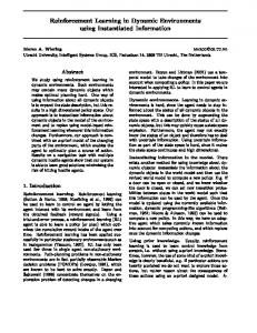
in which a label must be assigned to an object in the scene, indicating the category to which it belongs. The second involves the position and orientation estimation of the recognized object with respect to some global coordinate system attached to the scene. We adopt the viewpoint feature histogram (VFH) method to deal with the object recognition and six-degrees-of-freedom (6DoF) pose estimation will be discussed. It uses a two-dimensional Cartesian histogram grid as a world model, which is updated continuously and in real time with range data sampled by Kinect thus enabling realtime performance of the vision system. The remainder of the paper is organized as follows: Sect. 2 presents a brief review of recent literature on object recognition approaches in industrial vision that are relevant to our proposed vision system. The architecture and workflow of industrial vision monitoring systems are discussed in Sect. 3. Figure 1. The test platform of the monitoring system. Software and hardware tools, sensor alignment and object recognition approaches that are used in assisting the development of the proposed vision systems are presented in Sect. 4. full view of1. theThe working if their image correctly Section 5 summarizes the contribution of this work and plans Figure testsiteplatform ofdata thearemonitoring system aligned and fused. Experimental studies are carried out in the for future work. test platform which uses two Kinects and two ABB robots to represent the general case of multiple sensors and robots as 2 Related work Fig. 1 shows. While single 3-D sensors already provide detailed information within their field of view, complete coverage of a complete work area can only be achieved by reMuch research attention has been drawn to workpiece posilying on a multitude of these sensors. However, to provide tion and orientation estimation in the industrial robot area, useful information all data of each sensor must be aligned to which is the primary requirement of industrial robot moneach other, integrated and fused into an overall world picture. itoring. A good variety of approaches have been proposed Therefore, it is of vital importance for sensors to be aware of to solve object pose detection and their categorization. Litnot only its real-time pose in the real world but also their erature differentiates between model- and view-based aprelative position and orientation to each other, so as to reconproaches (Bennamoun and Mamic, 2002; Bicego et al., struct a 3-D view of the working site. 2005), feature- and appearance-based approaches or introTo be able to align the data correctly, the position and oriduces several classes (Belongie et al., 2002). Among all other entation of each sensor must be known with sufficient exmethods, the model of the object and the image data are actness. To address this problem, a fixed marker is introrepresented by local geometric features. Geometric feature duced into the system as an anchor. With the marker in sight, matching is used to interpret images through matching the the Kinect matches the marker’s location in the 2-D image model of object-to-data feature and estimating 3-D pose of with that in the real-world coordinate system to get the transthe model. The shape, texture or the appearance of the obformation from real-world coordinate system to the camera ject is always the center of attention. Because the object system. As individual Kinects are not fixed in the dynamic identification depends on this information to make reliable work area, there are circumstances where these Kinects do judgments by matching the model and scene data. We apply not detect the same geometrical marker for direct estimation the model-based pose estimation approach in our research, of relative pose between each other or where one or both which is done by matching geometric representations of a Kinects do not detect the anchor marker for self-positioning model of the object to those of the image data. Besides object pose estimation, sensor self-positioning is in the real world. Different relationships between Kinects and markers are considered and classified and corresponding soanother topic that researchers have been interested in and lutions are presented in the following section. many efforts have been made in using and comparing marker Other than being able to be aware of its sensing element’s and markerless pose estimation. Quite a few vision-based appose relative to each other and with regards to the world coorplications: camera calibration, augmented reality, etc., have dinates, a vision based monitoring system is required to interbenefited from the use of artificial 2-D and 3-D markers. pret a scene, which is defined as an instance of the real world These markers are designed to be easily detected and require consisting of one or more 3-D objects, to a determination very simple image processing operations. As to geometry, of which 3-D objects are where in the scene. Therefore two some applications are specially designed to avoid the troumain problems are involved: the first is object recognition, ble of estimating object pose. Typically, markerless object J. Sens. Sens. Syst., 3, 113–120, 2014
4
Y. Wang et al.: Work area monitoring in dynamic environments
www.j-sens-sens-syst.net/3/113/2014/
1 2
Y. Wang et al.: Work area monitoring in dynamic environments
3
Figure 1. The test platform of the monitoring system
115
1
4 5
Figure 2. System architecture.
6
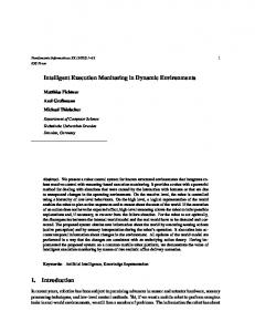
Figure 2. System Architecture
detection and pose estimation start with feature extraction (Canny, 1986; Forstner, 1994; Harris and Stephens, 1988; Smith and Brady, 1997). Other methods based on affine invariant regions determined around feature points were proposed (Kadir et al., 2004; Matas et al., 2002; Mikolajczyk and Schmid, 2004; Tuytelaars and Gool, 2004) in order to obtain invariance to out-of-plane rotations and translations. However, these algorithms are too time-consuming to meet the requirement of real-time computing speed. A registration method was proposed by State et al., 1996, using stereo images and a magnetic tracker. Vision techniques, multiple fiducial markers and square markers were used respectively for identifying 2-D matrix, markers robust tracking and fast tracking (Neumann et al., 1999; Rekimoto, 1998; Klinker et al., 1999). In our research, markers with distinct and simple geometrical patterns are used to attach on objects for recognizing and tracking, as they are easy to detect and recognize, thus achieving both robust and fast tracking. We are proposing a real-time self-aligning multi-sensor vision monitoring system for a dynamic work area. Modelbased pose estimation approach and VFH method are applied for object recognition and 6DoF estimation; anchor markers are used for sensor self-alignment and simple geometrical markers are attached on objects to distinguish and track them, which enables the monitoring system to be aware of the real-time position and pose status of sensing elements, robots and objects in it.
2
Figure 3. Workflow of the vision monitoring system.
3
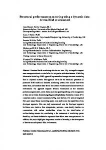
Figure 3. Workflow of the Vision Monitoring System
4
3
System overview
3.1 16
5 6
System architecture 3D Depth Camera
The monitoring mechanism of the proposed test system is shown in Fig. 2. The markers form geometric inference, which is used on a robot software development platform, ROS, to implement self-alignment of multi-sensors. An ROS RGB Camera is also used to create 3-D object point cloud models which Tilt Motor compose a model database for object recognition and pose estimation by matching module after the overall scene image Figure 4. Kinect is processed by segmentation and classification module. 3.2
Workflow
Figure 3 is the workflow of monitoring object’s movement in the work area. – Kinect launching: An ROS camera driver launches Kinect and outputs 2-D/3-D image data. – Calibration: calibrate a single Kinect with an anchor marker in work area. From the calibration the location of the points on the marker and its counterparts in the image, the transformation between marker and camera coordinates can be obtained. The location in the world coordinate is already known, thus, Kinect implements self-positioning. – Alignment: align every Kinect pair as a stereo camera. As two Kinects detect the same marker, they register their captured images at the corresponding points and compute the relative position and orientation between the Kinects, thus align the image from the two Kinects to visualize the work area.
www.j-sens-sens-syst.net/3/113/2014/
J. Sens. Sens. Syst., 3, 113–120, 2014
17
3
Figure 3. Workflow of the Vision Monitoring System
4Y. Wang et al.: Work area monitoring in dynamic environments
116
– Object model creation: create 3-D point-cloud model of object for later recognition and alignment.
3D Depth Camera – Object recognition: recognize and position the object from the scene. Object relative position and orientation will be obtained through aligning the object model to the point cloud of current scene. – Coordinate transformation: transform object pose which is relative to scene in camera coordinate system to global coordinate system. 4
RGB Camera
Tools and methods
Tilt Motor 4.1 4.1.1
Tools
5
Kinect
6 The robot has to rely on its sensory feedback to build a model of its surroundings. The 3-D sensor used in our research is Microsoft Kinect. It is able to capture the surrounding world in 3-D by combining the information from depth sensors and a standard RGB camera as shown in Fig. 4. The result of this combination is an RGB-D image with 640 × 480 resolution, where each pixel is assigned color information and depth information. In ideal conditions the resolution of the depth information can be as high as 3 mm, using 11 bit resolution. Kinect works with 30 Hz frequency for both RGB and depth cameras. On the left side of the Kinect is a laser infrared light source that generates electromagnetic waves with the wavelength of 830 nm. Information is encoded in light patterns that are deformed as the light reflects from objects in front of the Kinect. Based on these deformations captured by the sensor on the right side of RGB camera, a depth map is created. According to the light coding technology PrimeSense, this is not the time-of-flight method used in other 3-D cameras (Tolgyessy and Hubinsky, 2011). The interaction space is defined by the field of view of the Kinect cameras. To increase the possible interaction space, the built-in tilt motor supports an additional +27 and −27◦ , which also allows for the dynamic interaction in front of the sensor.
Figure 4. Kinect.
Figure 4. Kinect
simulation, etc. The Kinect node package provides a driver for using the Kinect RGB-D sensor with an ROS, which launches an OpenNI device and loads all nodelets to convert raw depth/RGB/IR streams to depth image, disparity image and registered point clouds. So it outputs point clouds, RGB image messages and its associated camera information for calibration, object recognition and alignment. 4.1.3
The point cloud library (PCL) (http://pointclouds.org) is a large-scale, open project for 2-D/3-D image and point cloud processing. The PCL framework contains numerous state-ofthe-art algorithms including filtering, feature estimation, surface reconstruction, registration, model fitting and segmentation. These algorithms can be used, for example, to filter outliers from noisy data, stitch 3-D point clouds together, segment relevant parts of a scene, extract key points and compute descriptors to recognize objects in the world based on their geometric appearance, and create surfaces from point clouds and visualize. 4.1.4
4.1.2
PCL
OpenCV
ROS
Robot operating system (ROS) (http://www.ros.org) is a software framework for robot software development, providing standard operating system services such as hardware abstraction, low-level device control implementation of commonly used functionality, message passing between processes, and package management. It is based on a graph architecture where nodes that receive, post and process messages from sensors, control, state, planning and actuactor. An ROS is composed of two main parts: the operating system ROS as described above and ROS-pkg, a suite of user contributed packages that implement functionality such as simultaneous localization and mapping, planning, perception, J. Sens. Sens. Syst., 3, 113–120, 2014
OpenCV (Open Source Computer Vision Library) (OpenCV.org) is an open source computer vision and machine learning software library. OpenCV was built to provide a common infrastructure for computer vision applications and to accelerate the use of machine perception in the commercial products. The library has a comprehensive set of both classic and state-of-the-art computer vision and machine learning algorithms.
www.j-sens-sens-syst.net/3/113/2014/
Y. Wang et al.: Work area monitoring in dynamic environments
117
1
Figure 6. The relationship between marker and camera coordinates.
2 3
Figure 6. The relationship between marker and camera coordinates
1 2 3
Figure 5. Four possible relative cases of multiple cameras.
Figure 5. Four possible relative cases of multiple cameras 4.2 Methods and mechanism
4.2.1
Sensor alignment
a. Kinect 1 can position itself by an anchor marker; Kinect 3 has no anchor marker in its sight but a geometrical marker. b. Both Kinect 3 and 4 detect no anchor marker but geometrical markers.
In the proposed vision monitoring system, multiple sensors 4 For case 1, Kinect 1 and 2 can use the anchor marker in sight are used and must be aligned to each other and fused into for their own 3-D pose estimation by relating camera meaan overall world picture. In order to align the sensing 5data with measurements the real, three-dimensional accurately, the position and orientation of each sensor are 6 of Figure 7.surements Overlapping of 7 point clouds at differentin viewpoints world. In this model, a marker scene view is formed by pro7 priority for aligning the sensing data accurately. Our work jecting 3-D points of the marker into the image plane using a employs two types of 2-D markers respectively fixed on8 the perspective transformation as Fig. 6 shows. work area as landmarks for camera self-positioning and9 atProjective transform maps the points Qm in the global 10 tached on the objects as name tags for object identification, world coordinate system (Xm , Ym , Zm ) to the points on the 19 namely anchor markers and geometrical markers. The introimage plane with coordinates (xi , yi ) and to the points on duction of anchor markers and geometrical markers ensures camera plane with coordinates (Xc , Yc , Zc ). The projection the reconstruction of the whole scene of the work area. Infrom global world coordinate system to camera image coorstead of being fixed in the work area, Kinect moves up and dinate system can be summarized as in Eq. (1): down, left and right on its base to obtain visual information of the work scene from different viewpoints. Therefore, the spatial relationships of anchor markers, geometrical markXc r11 r12 r13 t1 Xm Yc r21 r22 r23 t2 Ym ers and Kinects vary from time to time. The relative pose of (1) Zc = r31 r32 r33 t3 Zm . Kinect can be generally summarized and classified into four cases, as shown in Fig. 5: 1 0 0 0 1 1 18
1. Kinect 1 and Kinect 2 have at least one anchor marker in their intersected vision area. 2. Kinect 2 and Kinect 3 have at least one distinguishing marker and no anchor marker in their intersected vision area. 3. Two Kinects have no common marker in their intersected vision area: www.j-sens-sens-syst.net/3/113/2014/
For case 2, Kinect 2 and 3 capture the same non-anchor marker. For any given 3-D point P in object coordinates, we can put P in the camera coordinates Pl = Rl P + T l and Pr = Rr P + T r for the left and right cameras, respectively. It is also evident that the two views of P (from the two cameras) are related to Pl = RT (Pr − T ), where R and T are, respectively, the rotation matrix and translation vector between the cameras. Taking these three equations and solving for the rotation and translation separately yields the following J. Sens. Sens. Syst., 3, 113–120, 2014
2 3
118 Figure
Wang et al.: Work area monitoring in dynamic environments 6. The relationship between marker Y.and camera coordinates
1 2 3 4 5 6 7
4 5 6 7 8 9 10
Figure 7. Overlapping of 7 point clouds at different viewpoints.
8
Figure 8. Merging of 34 point clouds at 34 different viewpoints.
9 Fig.8 Merging of 34 point clouds at 34 different view to get final transformation and a fitness score to evaluate the simple relations (OpenCV.org): Figure 7. Overlapping of 7 point clouds at different aligningviewpoints results. R = Rr (Rl )T , T = T r − RT l .
(2) (3)
Then the relative rotation and translation from Kinect 1 to Kinect 2 can be obtained, and in the chain of Kinects that detect the same marker with Kinect 2 directly or indirectly, there must be one that has an anchor marker in vision range. Therefore, the second case can be solved in the same way as case 1, only with the corresponding transformations. For case 3, Kinect 1 and Kinect 3 do not have the same marker in their vision ranges. We apply a similar strategy here by searching for an anchor marker in the chain composed of overlapped Kinects to estimate the 6DoF pose of at least one Kinect and then to make pose estimation of others through coordinate transformation. 4.2.2
Object Recognition and 6DoF pose estimation
Object recognition is the process of automatic identification and localization of objects from the sensed images of scenes in the real world. For object recognition in this system, scene point clouds with the object’s presence are downsampled by corresponding sampling algorithm from PCL for analysis and computation. To obtain the surface normals of the specified input point clouds, Kd-Tree (http://ros.org) is used to search for neighboring point and the radius that defines each point’s neighborhood. The VFH (http://pointclouds.org) descriptor is employed as a representation for point cluster recognition and its 6DoF pose estimation. The computation of VFH descriptors is implemented from the input point cloud and its surface normals. The resulted features are invariant to image scaling, translation, rotation and partially invariant to illumination changes and affine or 3-D projection. With the normals and local feature descriptors, the object point cloud model is aligned into the current scene cloud J. Sens. Sens. Syst., 3, 113–120, 2014
Object recognition is achieved by matching features derived from the scene with stored object model representations. One of the most common ways to create the object model for recognition is to extract the target as a cluster from the point cloud. However, in this way only a partial model is created out of the object, which provides very limited information for object identification.
19
Model creation
In this research, the approach adopted to create a 3-D point cloud model from an object is to use an object recording API of the package RoboEarth from an ROS along with a Kinect camera and a marker pattern. The target object is placed in the middle of the marker template and either the camera or marker pattern and object are moved to record a complete pose. It is always a better idea to move the object, otherwise the illumination might not be constant and therefore color effects might arise. Figure 7 shows the overlapping of point clouds of the object captured at seven different viewpoints and all the point clouds are created at 34 different viewpoints and are finally processed and merged into one 3-D point cloud model as Fig. 8 shows. Normal estimation
Given a geometric surface, it is usually trivial to infer the direction of the normal at a certain point on the surface as the vector perpendicular to the surface in that point. The problem of determining the normal to a point on the surface is approximated by the problem of estimating the normal of a plane tangent to the surface, which in turn becomes a least-square plane fitting estimation problem. The solution for estimating www.j-sens-sens-syst.net/3/113/2014/
Y. Wang et al.: Work area monitoring in dynamic environments
the surface normal is therefore reduced to an analysis of the eigenvectors and eigenvalues of a covariance matrix created from the nearest neighbors of the query point. More specifically, for each point pi , we assemble the covariance matrix C as follows: C=
k 1X (pi − p)·(p ¯ ¯ T, i − p) k i=1
C · v¯j = λj · v¯j , j ∈ {0, 1, 2},
119
For cos(αi ), cos(βi ) and θi histograms with 45 bins each are computed and a histogram of 128 bins for cos(βi ), thus the VFH descriptor has 263 dimensions (Aldoma and Vincze, 2011). Pose estimation
(4) (5)
where k is the number of point neighbors considered in the neighborhood of pj , p represents the 3-D centroid of the nearest neighbors, λj is the j th eigenvalue of the covariance matrix, and vj the j th eigenvector (Bradski and Kaehler, 2008).
As the point cloud data of an object model is stored and the corresponding Kd-tree representation is built up, objects are extracted from the given scene as clusters and for each of them, an individual cluster; for each cluster, their VFH descriptor from the current camera position is computed for searching for candidates in the trained Kd-tree. After find the best candidate for recognition, the position and orientation of the object that the model represents can be determined by registering the model to the scene point cloud.
Feature description 5
Features define individual components of an image and can be categorized into two major groups: global features and local features. Global features are defined as properties of an image based on the whole image. Local features are defined as properties of an image based on a component of the image and these will be used for object recognition. Therefore, we need a way to describe the features of an image. VFH descriptor is a novel representation for point cluster recognition and its 6DoF pose estimation. VFH has its roots in FPFH (Fast Point Feature Histograms) descriptor and add in viewpoint variance while retaining invariance to scale. The main idea of object recognition through VFH descriptors is to formulate the recognition problem as a nearest neighborhood estimation problem. Let pc and nc be the centroids of all surface points and their normals of a given object partial view in the camera coordinate system (with ||nc || = 1). Then (ui , vj , wi ) defines a Darboux coordinate frame for each point pi : ui = nc , pi − pc × ui , vi = ||pi − pc || wi = ui × vi .
(6) (7) (8)
The normal angular deviations cos(αi ), cos(βi ) and cos(ϕi ) for each point pi and its normal ni given by cos(αi ) = vi · ni , pc cos(βi ) = ni · , ||pc || pi − pc cos(ϕi ) = ui · , ||pi − pc || θi = a tan 2(wi · ni , ui · ni ).
(9) (10)
Conclusions
In this paper, we have introduced a new approach for work area monitoring in a dynamic environment using multiple 3D self-aligning Kinects. The anchor marker is used to calibrate Kinect to correct for the main deviations from the pinhole model that Kinect uses, to obtain the transformations from a global coordinate system to a camera coordinate system and relative position and orientation between the Kinects. In this way, Kinect is able to have an awareness of its own positions and 6DoF poses as well as the object’s location in the working scenario at any moment, enabling robots to accommodate changes in the workpiece position/orientation and to perform complex operations like automated assembling and sorting. Simple geometrical markers are used to distinguish objects, which achieves robust and fast tracking of objects in dynamic work sites. In conclusion, addressing the requirements of real-time monitoring of a dynamic industrial production area, the proposed vision monitoring system is able to provide overall vision of the work area and estimate 6DoF pose of multiple objects with defined geometrical markers and anchor markers. To evaluate and optimize the performance of our proposed approaches in this vision system, we will involve the following aspects as future research topics. Firstly, adopt color information for object recognition and extraction; secondly, implement boundary analysis using the combination of a photogrammetric processing algorithm and point cloud spatial information; thirdly, compare the results of using different models to align to scene image: 3-D CAD model, model generated based on both digital image and point cloud obtained by depth camera, scanned object 3-D point cloud model and object model extracted from the scene image.
(11) (12)
Edited by: R. Tutsch Reviewed by: two anonymous referees
Note that cos(αi ), cos(βi ) and θi are invariant to viewpoint changes, given that the set of visible points does not change. www.j-sens-sens-syst.net/3/113/2014/
J. Sens. Sens. Syst., 3, 113–120, 2014
120 References Aldoma, A. and Vincze, M.: CAD-Model Recognition and 6DOF Pose Estimation Using 3D Cues, IEEE International Conference on Computer Vision Workshops, 585–592, 2011. Belongie, S., Malik, J., and Puzicha, J.: Shape matching and object recognition using shape contexts, IEEE T. Pattern Anal., 24, 509– 522, 2002. Bennamoun, M. and Mamic, G. J.: Object recognition: fundamentals and case studies, London, Springer, 2002. Bicego, M., Castellani, U., and Murino, V.: A hidden Markov model approach for appearance-based 3D object recognition, Pattern Recognition, 26, 2588–2599, 2005. Bradski, G. and Kaehler, A.: Learning OpenCV: Computer Vision with the OpenCV Library, O’Reilly, 378–386, 2008. Canny, J. F.: A computational approach to edge detection, IEEE T. Pattern Anal., 8, 679–698, 1986. Ewert, D., Mayer, M., Schilberg, D., and Jeschke, S.: Adaptive assembly planning for a nondeterministic domain, Conference Proceedings of the 4th International Conference on Applied Human Factors and Ergonomics, 1253–1262, 2012. Forstner, W.: A framework for low-level feature extraction, European Conf. on Computer Vision, 383–394, 1994. Harris, C. and Stephens, M.: A combined corner and edge detector, Proc. of the 4th Alvey Vision Conf., 147–151, 1988. Kadir, T., Zisserman, A., and Brady, M.: An affine invariant salient region detector, European Conf. on Computer Vision, 2004. Klinker, G., Stricker, D., and Reiners, D., Augmented Reality: A Balancing Act between High Quality and Real-Time Constraints, Proceedings of ISMR ’99, 325–346, 1999.
J. Sens. Sens. Syst., 3, 113–120, 2014
Y. Wang et al.: Work area monitoring in dynamic environments Matas, J., Chum, O., Urban, M., and Pajdla, T.: Robust wide baseline stereo from maximally stable extremal regions, British Machine Vision Conf., 2002. Mikolajczyk, K. and Schmid, C.: Scale & affine invariant interest point detectors, Int. J. Comput. Vision, 60, 63–86, 2004. Neumann, U., You, S., Cho, Y., and Lee, J.: Augmented Reality Tracking in Natural Environments, Mixed Reality – Merging Real and Virtual Worlds, Ohmsha and Springer-Verlag, 101–130, 1999. OpenCV.org: http://docs.opencv.org/modules/calib3d/doc/camera_ calibration_and_3d_reconstruction.html (last access: 9 April 2013). PCL: http://www.pointclouds.org/documentation/tutorials/ (last access: 9 April 2013), http://ros.org, http://www.ros.org/wiki/ (last access: 9 April 2013). Rekimoto, J.: Matrix: A Realtime Object Identification and Registration Method for Augmented Reality, Proceedings of Asia Pacific Computer Human Interaction, 15–17, 1998. Smith, S. M. and Brady, J. M.: A New Approach to Low Level Image Processing, Int. J. Comput. Vision, 23, 45–78, 1997. State, A., Hirota, G., Chen, D. T., Garrett, W. F., and Livingston, M. A.: Superior Augmented Reality Registration by Integrating Landmark Tracking and magnetic Tracking, Proceedings of SIGGRAPH96, 429–446, 1996. Tolgyessy, M. and Hubinsky, P.: The Kinect Sensor in Robotics Education, In Proceedings of 2nd International Conference on Robotics in Education. Vienna, Austria, 143–146, 2011. Tuytelaars, T. and Gool, L. Vn.: Matching Widely Separated Views Based on Affine Invariant Regions, Kluwer Academic Publishers, 2004.
www.j-sens-sens-syst.net/3/113/2014/