Mar 14, 2005 - Convert heading values of 34 and 3.5 to EH-command values. ..... Sends CSS-DVL output data structure (without sensor and made-good data).
WorkHorse Monitor, Sentinel, Mariner, Rio Grande, Quartermaster, H-ADCP, Navigator, and Long Ranger ADCPs
Commands and Output Data Format
P/N 957-6156-00 (March 2005)
RD Instruments Acoustic Doppler Solutions
Table of Contents 1
Introduction to WorkHorse Commands ......................................................................................... 1 1.1 1.1.1 1.1.2 1.2 1.3 1.4 1.5
2
Data Communication and Command Format......................................................................................2 Command Input Processing................................................................................................................2 Data Output Processing ......................................................................................................................3 Firmware Updates...............................................................................................................................4 Feature Upgrades ...............................................................................................................................5 Using Direct Commands to Deploy your ADCP ..................................................................................7 Command Summary ...........................................................................................................................8
Command Descriptions ................................................................................................................. 13
2.1 2.1.1
2.1.2 2.2 2.2.1 2.2.2
2.3 2.3.1
2.3.2
? – Help Menus.................................................................................................................................13 Break ................................................................................................................................................14 Expert Mode......................................................................................................................................15 OL - Features....................................................................................................................................15 Compass Commands .......................................................................................................................16 Standard Compass Commands ........................................................................................................16 AF – Field Calibrate Compass ..........................................................................................................16 AR – Return to Factory Calibration ...................................................................................................17 AX – Examine Compass Calibration .................................................................................................17 AZ – Zero Pressure Sensor ..............................................................................................................18 Expert Compass Commands ............................................................................................................19 AC – Output Active Calibration Data.................................................................................................19 AD – Display Factory or Active Calibration Data...............................................................................20 Bottom Track Commands .................................................................................................................21 Standard Bottom Track Commands..................................................................................................21 BP – Bottom-Track Pings Per Ensemble ..........................................................................................21 BX – Maximum Tracking Depth ........................................................................................................22 Expert Bottom Track Commands ......................................................................................................23 BA - Evaluation Amplitude Minimum .................................................................................................23 BB – High Bandwidth Maximum Depth .............................................................................................23 BC - Correlation Magnitude Minimum ...............................................................................................24 BD - Delay before Reacquire ............................................................................................................24 BE - Error Velocity Maximum ............................................................................................................25 BF - Depth Guess .............................................................................................................................25 BI - Gain Switch Depth......................................................................................................................26 BK - Water-Mass Layer Mode...........................................................................................................26 BL - Water-Mass Layer Parameters..................................................................................................27 BM - Bottom Track Mode ..................................................................................................................28 BN – Speed Log Hold/Drop Control ..................................................................................................30 BO - Distance Measure Filter Constant ............................................................................................30 BR - Resolution.................................................................................................................................31 BS - Clear Distance Traveled............................................................................................................32 BV – Mode 7 Parameters..................................................................................................................32 BW - Water Reference Interval .........................................................................................................33 BZ - Coherent Ambiguity Velocity .....................................................................................................33 Control System Commands ..............................................................................................................34 Standard Control System Commands...............................................................................................34 CB - Serial Port Control ....................................................................................................................34 CF - Flow Control..............................................................................................................................36 CK - Keep Parameters ......................................................................................................................37 CP – Polled Mode .............................................................................................................................37 CQ – Transmit Power .......................................................................................................................38 CR – Retrieve Parameters ................................................................................................................38 CS – Start Pinging (Go) ....................................................................................................................39 CX – Low Latency Trigger Enable ....................................................................................................39 CZ – Power Down WorkHorse ..........................................................................................................40 Expert Control System Commands...................................................................................................41 CA - Control Periodic Output.............................................................................................................41 CC - Choose External Devices .........................................................................................................41
2.4 2.4.1
2.4.2
2.5 2.5.1 2.6 2.6.1
2.6.2
2.7 2.7.1
2.7.2
CD – Serial Data Out ........................................................................................................................42 CE - Retrieve Most Recent Data Ensemble ......................................................................................42 CH – Suppress Banner .....................................................................................................................44 CI – Instrument ID.............................................................................................................................44 CL - Battery Saver Mode ..................................................................................................................44 CM - Master ......................................................................................................................................45 CN - Save NVRAM to Recorder........................................................................................................45 CT - Turnkey Operation ....................................................................................................................46 CY - Clear Error Status Word............................................................................................................47 Environmental Commands................................................................................................................49 Standard Environmental Commands ................................................................................................49 EA - Heading Alignment....................................................................................................................49 EB - Heading Bias.............................................................................................................................49 ED - Depth of Transducer .................................................................................................................50 ES – Salinity......................................................................................................................................50 EX – Coordinate Transformation.......................................................................................................51 EZ - Sensor Source ..........................................................................................................................52 Expert Environmental Commands ....................................................................................................54 EC - Speed of Sound ........................................................................................................................54 EF - Pressure Smoothing Constant ..................................................................................................54 EH - Heading ....................................................................................................................................55 EP - Pitch (Tilt 1)...............................................................................................................................55 EQ – Enable Single Beam Data........................................................................................................56 ER - Roll (Tilt 2) ................................................................................................................................56 ET - Temperature..............................................................................................................................57 Fault Log Commands........................................................................................................................58 Standard Fault Log Commands ........................................................................................................58 FC – Clear Fault Log.........................................................................................................................58 FD – Display Fault Log .....................................................................................................................58 Performance and Testing Commands ..............................................................................................59 Standard Performance and Testing Commands ...............................................................................59 PA – Pre-deployment Tests ..............................................................................................................59 PC – User-Interactive Built-In Tests..................................................................................................60 PS – Display System Parameters .....................................................................................................61 Expert Performance and Testing Commands ...................................................................................63 PB - Bin Select for PD12 Data Output Type......................................................................................63 PD - Data Stream Select...................................................................................................................63 PE - PD12 Ensemble Select .............................................................................................................64 PF – Pre-Deployment Test Summary ...............................................................................................65 PM - Distance Measurement Facility ................................................................................................66 PO - PD12 Velocity Component Select.............................................................................................66 PT - Built-In Tests .............................................................................................................................67 PT Test Results Error Codes ............................................................................................................67 PT0 - Help.........................................................................................................................................67 PT2 - Ancillary System Data .............................................................................................................68 PT3 - Receive Path...........................................................................................................................68 PT4 - Transmit Path..........................................................................................................................69 PT5 - Electronics Wrap Around.........................................................................................................70 PT6 - Receive Bandwidth..................................................................................................................72 PT7 - RSSI Bandwidth ......................................................................................................................72 Recorder Commands ........................................................................................................................74 Standard Recorder Commands ........................................................................................................74 RE – Erase Recorder ........................................................................................................................74 RF – Recorder Free Space (Bytes)...................................................................................................74 RN – Set Deployment Name.............................................................................................................75 RR – Show Recorder File Directory ..................................................................................................75 RY – Upload Recorder Files .............................................................................................................76 Expert Recorder Commands.............................................................................................................77 RA - Number of Deployments ...........................................................................................................77 RB - Recorder Built-In Test ...............................................................................................................77 RD - Create Recorder File ................................................................................................................78 RI – Deployment Auto Increment ......................................................................................................79
2.8 2.8.1
2.8.2
2.9 2.9.1
2.9.2
2.9.3
3
RS - Recorder Free Space (Megabytes)...........................................................................................81 Timing Commands............................................................................................................................82 Standard Timing Commands ............................................................................................................82 TE – Time Per Ensemble ..................................................................................................................82 TF – Time of First Ping .....................................................................................................................82 TG – Time of First Ping (Y2k Compliant) ..........................................................................................83 TP – Time Between Pings.................................................................................................................84 TS – Set Real-Time Clock.................................................................................................................85 TT – Set Real-Time Clock (Y2k Compliant) ......................................................................................86 Expert Timing Commands.................................................................................................................87 TB - Time Per Burst ..........................................................................................................................87 TC - Ensemble Per Burst ..................................................................................................................88 TX – Buffered Output Period.............................................................................................................88 Water Profiling Commands ...............................................................................................................89 Standard Water Profiling Commands................................................................................................89 WB - Mode 1 Bandwidth Control.......................................................................................................89 WD – Data Out..................................................................................................................................90 WF – Blank after Transmit ................................................................................................................91 WN – Number of Depth Cells............................................................................................................91 WP – Pings Per Ensemble................................................................................................................92 WS – Depth Cell Size .......................................................................................................................92 WV – Ambiguity Velocity ...................................................................................................................93 Expert Water Profiling Commands....................................................................................................95 WA - False Target Threshold Maximum ...........................................................................................95 WC - Low Correlation Threshold.......................................................................................................95 WE - Error Velocity Threshold...........................................................................................................96 WI - Clip Data Past Bottom ...............................................................................................................96 WJ - Receiver Gain Select ................................................................................................................96 WL - Water Reference Layer ............................................................................................................97 WQ - Sample Ambient Sound ...........................................................................................................97 WT - Transmit Length .......................................................................................................................98 WU - Ping Weight .............................................................................................................................98 High Resolution Water Profiling ........................................................................................................99 WK – Depth Cell Size Override (Mode 11/12 Only) ..........................................................................99 WM - Profiling Mode .........................................................................................................................99 WO – Mode 12 Parameters ............................................................................................................ 100 WZ - Mode 5 Ambiguity Velocity ..................................................................................................... 101
Advanced Commands .................................................................................................................. 102 3.1
3.2
3.3
Sound Velocity Smart Sensor Commands ...................................................................................... 102 DB - RS-485 Port Control................................................................................................................ 102 DS - Load SpeedOfSound with SVSS Sample (BIT Result) ........................................................... 102 DW - Current ID on RS-485 Bus ..................................................................................................... 103 DX - Set SVSS to RAW Mode......................................................................................................... 103 DY - Set SVSS to REAL Mode........................................................................................................ 103 DZ - Get Single SCAN from SVSS.................................................................................................. 104 Waves Commands.......................................................................................................................... 105 HA – Waves False Target Threshold ..............................................................................................105 HB – Automatically Chosen Bins for Wave Processing ..................................................................105 HD – Waves Data Out .................................................................................................................... 106 HF – Waves Flow Control ............................................................................................................... 106 HP – Waves Pings per Wave Record ............................................................................................. 107 HR – Time Between Wave Records ............................................................................................... 107 HS – Bins for Directional Wave Spectrum....................................................................................... 108 HT – Time Between Wave Record Pings........................................................................................ 108 HV – Bins for Velocity Spectrum ..................................................................................................... 109 Lowered ADCP Commands ............................................................................................................ 110 LA – LADCP False Target Threshold Maximum ............................................................................. 110 LC – LADCP Low Correlation Threshold ........................................................................................ 110 LD – LADCP Data Out .................................................................................................................... 111 LF – LADCP Blank after Transmit................................................................................................... 112 LJ - Receiver Gain Select ............................................................................................................... 112
LN – Number of Depth Cells ........................................................................................................... 113 LP – Pings Per Ensemble ............................................................................................................... 113 LS – Depth Cell Size....................................................................................................................... 113 LV – Ambiguity Velocity .................................................................................................................. 114 LW - Bandwidth Control .................................................................................................................. 114 LZ – LADCP Amplitude and Correlation Thresholds.......................................................................115 Ping Synchronization Commands ................................................................................................... 116 SA - Synchronize Before/After Ping/Ensemble ............................................................................... 116 SI - Synchronization Interval ........................................................................................................... 117 SM - RDS3 Mode Select ................................................................................................................. 117 SS - RDS3 Sleep Mode .................................................................................................................. 118 ST - Slave Timeout ......................................................................................................................... 118 SW - Synchronization Delay ........................................................................................................... 119
3.4
4
Introduction to Output Data Format ........................................................................................... 120 4.1 4.2
5
Hexadecimal-ASCII Output Data .................................................................................................... 120 Binary Output Data Format ............................................................................................................. 120
PD0 Output Data Format .............................................................................................................. 121 5.1 5.2 5.3
Header Data Format ....................................................................................................................... 123 Fixed Leader Data Format .............................................................................................................. 125 Variable Leader Data Format.......................................................................................................... 131 How Does the WorkHorse Sample Depth and Pressure?............................................................... 137 Converting kpa to Depth ................................................................................................................. 137 Velocity Data Format ...................................................................................................................... 138 Correlation Magnitude, Echo Intensity, and Percent-Good Data Format ........................................ 140 Binary Bottom-Track Data Format .................................................................................................. 144 Binary Reserved BIT Data Format .................................................................................................. 149 Binary Checksum Data Format ....................................................................................................... 149
5.4 5.5 5.6 5.7 5.8
6
Special Output Data Formats ...................................................................................................... 150 6.1 6.2 6.3 6.4 6.5 6.6 6.7 6.8 6.9 6.10 6.11 6.12 6.13 6.14 6.15 6.15.1 6.15.2 6.16 6.17 6.18
7
DVL Binary Data Format (PD3)....................................................................................................... 151 DVL Output Data Format (PD3) Details .......................................................................................... 153 DVL Binary Data Format (PD4/PD5)...............................................................................................155 DVL Output Data Format (PD4/PD5) Details .................................................................................. 157 DVL Binary Data Format (PD5)....................................................................................................... 160 DVL Output Data Format (PD5) Details .......................................................................................... 162 DVL Output Data Format (PD6) ...................................................................................................... 163 PD8 ASCII Output........................................................................................................................... 165 PD9 ASCII Output........................................................................................................................... 166 DVL Binary Data Format (PD10)..................................................................................................... 167 DVL Output Data Format (PD10) Details ........................................................................................ 169 Navigator NMEA Output (PD11) ..................................................................................................... 171 Reduced Data Output Format (PD12)............................................................................................. 173 DVL Output Data Format (PD13) .................................................................................................... 175 H-ADCP Condensed 2D Output Format (PD14) ............................................................................. 177 Format ............................................................................................................................................ 177 Invalid Data ..................................................................................................................................... 177 Output Data Format (PD15) ............................................................................................................ 179 Output Data Format (PD16) ............................................................................................................ 180 Output Data Format (PD18) ............................................................................................................ 180
How to Decode an ADCP Ensemble ........................................................................................... 181 7.1 7.2 7.3 7.4 7.5
8
Rules for the BroadBand Data Format PD0 .................................................................................... 181 Recommended Data Decoding Sequence for BroadBand Data Format PD0 ................................. 182 Pseudo-Code for Decoding PD0 Ensemble Data ........................................................................... 182 Pseudo-Code for Decoding PD5 Ensemble Data ........................................................................... 183 Example Code for Decoding BroadBand Ensembles...................................................................... 184
Firmware History .......................................................................................................................... 189 8.1 8.2 8.3
WorkHorse 16.xx History ................................................................................................................ 189 Workhorse Rio Grande Firmware History ....................................................................................... 192 WorkHorse Navigator DVL Firmware History.................................................................................. 193
List of Figures Figure 1. Figure 2. Figure 3. Figure 4. Figure 5. Figure 6. Figure 7. Figure 8. Figure 9. Figure 10. Figure 11. Figure 12. Figure 13. Figure 14. Figure 15. Figure 16. Figure 17. Figure 18. Figure 19. Figure 20. Figure 21.
Firmware Update............................................................................................................. 4 RDIFlash Firmware Upgrade Utility Screen..................................................................... 4 Installing Feature Upgrades ............................................................................................ 5 Feature Upgrade Completed ........................................................................................... 6 Software Break Setup in WinRiver ................................................................................ 14 Water-Mass Layer Processing ...................................................................................... 27 ADCP Coordinate Transformation ................................................................................. 52 PT7 RSSI Bandwidth Test ............................................................................................. 73 PD0 Standard Output Data Buffer Format ................................................................... 121 Binary Header Data Format......................................................................................... 123 Fixed Leader Data Format .......................................................................................... 126 Variable Leader Data Format ...................................................................................... 132 Velocity Data Format ................................................................................................... 138 Binary Correlation Magnitude, Echo Intensity, and Percent-Good Data Format .......... 140 Binary Bottom-Track Data Format ............................................................................... 146 Binary Reserved BIT Data Format............................................................................... 149 Binary Checksum Data Format ................................................................................... 149 DVL Binary Data Format (PD3) ................................................................................... 152 DVL Binary Data Format (PD4/PD5) ........................................................................... 156 DVL Binary Data Format (PD5) ................................................................................... 161 DVL Binary Data Format (PD10) ................................................................................. 168
List of Tables Table Table Table Table Table Table Table Table Table Table Table Table Table Table Table Table Table Table Table Table Table Table Table
1: 2: 3: 4: 5: 6: 7: 8: 9: 10: 11: 12: 13: 14: 15: 16: 17: 18: 19: 20: 21: 22: 23:
ADCP Minimum Required Commands for Deployments.................................................. 7 WorkHorse Input Command Summary ............................................................................ 8 WorkHorse Factory Defaults ......................................................................................... 11 Water-Mass Reference-Layer Modes ............................................................................ 26 BM4/BM5 Minimum Tracking Depths ............................................................................ 28 BM7 Minimum Tracking Depths..................................................................................... 30 Serial Port Control......................................................................................................... 34 Baud Rate ..................................................................................................................... 35 Flow Control .................................................................................................................. 36 Polled Mode Commands ............................................................................................... 37 Retrieve Parameters ..................................................................................................... 38 Error Status Word.......................................................................................................... 47 Coordinate Transformation Processing Flags................................................................ 51 Sensor Source Switch Settings ..................................................................................... 53 Data Stream Selections................................................................................................. 64 Pre-Deployment Test Summary BIT Result ................................................................... 65 Error Code Hex to Binary Conversion ........................................................................... 67 PT3 Failure ................................................................................................................... 69 PT4 Failure ................................................................................................................... 70 PT5 Results................................................................................................................... 71 PT6 Receive Bandwidth Nominal Values ...................................................................... 72 Bandwidth Control ......................................................................................................... 89 WV-command Maximum Setting (20 Degree) ............................................................... 94
Table Table Table Table Table Table Table Table Table Table Table Table Table Table Table Table Table Table Table Table Table Table Table Table Table Table
24: 25: 26: 27: 28: 29: 30: 31: 32: 33: 34: 35: 36: 37: 38: 39: 40: 41: 42: 43: 44: 45: 46: 47: 48: 49:
Ping Weights ................................................................................................................. 98 Water Modes ............................................................................................................... 100 Waves Flow Control .................................................................................................... 107 Lowered ADCP Depth Cell Size .................................................................................. 114 Bandwidth Control ....................................................................................................... 115 Synchronization Parameters ....................................................................................... 116 Sleep Mode Parameters.............................................................................................. 118 Header Data Format.................................................................................................... 124 Fixed Leader Data Format .......................................................................................... 127 Variable Leader Data Format ...................................................................................... 133 Velocity Data Format ................................................................................................... 139 Correlation Magnitude Data Format ............................................................................ 141 Echo Intensity Data Format......................................................................................... 141 Percent-Good Data Format ......................................................................................... 143 Bottom-Track Data Format .......................................................................................... 147 Reserved for RDI Format ............................................................................................ 149 Checksum Data Format .............................................................................................. 149 DVL Output Data Format (PD3) Details....................................................................... 153 DVL Output Data Format (PD4/PD5) Details ............................................................... 157 DVL Output Data Format (PD5) Details....................................................................... 162 DVL Output Data Format (PD6)................................................................................... 163 DVL Output Data Format (PD10) Details..................................................................... 169 Reduced Data Output Format (PD12) ......................................................................... 174 DVL Output Data Format (PD13)................................................................................. 175 PD14 Output Data Format........................................................................................... 178 Common Data Format IDs........................................................................................... 181
WorkHorse Commands and Output Data Format
Acoustic Doppler Solutions
WorkHorse Commands 1
Introduction to WorkHorse Commands This guide defines the commands used by the WorkHorse Monitor, Sentinel, Mariner, Rio Grande, Navigator, and Long Ranger ADCPs. These commands (Table 2, page 8) let you set up and control the WorkHorse without using an external software program such as our WinSC, Waves, VmDas, and WinRiver programs. However, we recommend you use our software to control the WorkHorse because entering commands directly from a terminal can be difficult. Make sure you read and understand “Using Direct Commands to Deploy your ADCP,” page 7 before deploying your ADCP. Most WorkHorse settings use factory-set values (Table 3, page 11). If you change these values without thought, you could ruin your deployment. Be sure you know what effect each command has before using it. Call RDI if you do not understand the function of any command. Using WinSC for self-contained deployments or VmDas/Waves/WinRiver for real-time deployments to develop the command file will ensure that the WorkHorse is set up correctly. The commands shown in Table 2, page 8 directly affect the range of the ADCP, the standard deviation (accuracy) of the data, and battery usage. NOTE. This guide applies to Workhorse Monitor, Sentinel, Mariner, Quartermaster, and Long Ranger firmware version 16.26, Navigator firmware 9.19, H-ADCP firmware version 11.05, and Rio Grande firmware 10.13. When new firmware versions are released, some commands may be modified, added, or removed. Read the README file on the upgrade disk. When an addition or correction to this manual is needed, an Interim Change Notice (ICN) will be posted to our web site. Please check our RDI’s web site often at www.rdinstrument.com.
P/N 957-6156-00 (March 2005)
page 1
WorkHorse Commands and Output Data Format
1.1
Data Communication and Command Format You can enter commands with an IBM-compatible computer running RDI’s BBTalk. The WorkHorse communicates with the computer through an RS-232 (or RS-422) serial interface. We initially set the WorkHorse at the factory to communicate at 9600 baud, no parity, and one stop bit. Immediately after you apply power to the WorkHorse, it enters the STANDBY mode. Send a BREAK signal using BBTalk by pressing the End key. When the WorkHorse receives a BREAK signal, it responds with a wake-up message similar to the one shown below. The WorkHorse is now ready to accept commands at the “>” prompt from either a terminal or computer program. [Break Wakeup A] Workhorse Broadband ADCP Version 16.xx RD Instruments (c) 1996-2005 All rights reserved. >
NOTE. If you use a terminal/program other than BBTalk, the BREAK length (up to down transition) must last at least 300 ms.
1.1.1
Command Input Processing Input commands set WorkHorse operating parameters, start data collection, run built-in tests (BIT), and asks for output data. All commands are ASCII character(s) and must end with a carriage return (CR). For example, >WP0001 [Your input]
If the entered command is valid, the WorkHorse executes the command. If the command is one that does not provide output data, the WorkHorse sends a carriage return line feed and displays a new “>” prompt. Continuing the example, >WP00001 >
[Your original input] [WorkHorse response to a valid, no-output command]
If you enter a valid command that produces output data, the WorkHorse executes the command, displays the output data, and then redisplays the “>” prompt. Some examples of commands that produce output data are ? (help menus), CS (start pinging), PS (system configuration data), and PA (run built-in tests). If the command is not valid, the WorkHorse responds with an error message similar to the following. >WPA >WPA ERR 002: >
NUMBER EXPECTED
[Your input] [WorkHorse response]
After correctly entering all the commands for your application, you would send the CS-command to begin the data collection cycle.
page 2
RD Instruments
WorkHorse Commands and Output Data Format
1.1.2
Data Output Processing After the WorkHorse completes a data collection cycle, it sends a block of data called a data ensemble. A data ensemble consists of the data collected and averaged during the ensemble interval (see TE-command). A data ensemble can contain header, leader, velocity, correlation magnitude, echo intensity, percent good, and status data. WorkHorse output data can be in either hexadecimal-ASCII (Hex-ASCII) or binary format (set by CF-command). The Hex-ASCII mode is useful when you use a terminal to communicate with, and view data from the WorkHorse. The binary mode is useful for high-speed communication with a computer program. You would not use the binary mode to view data on a terminal because the terminal could interpret some binary data as control codes. NOTE. All of RD Instruments’ software supports binary PD0 Output Data Format only.
When data collection begins, the WorkHorse uses the settings last entered (user settings) or the factory-default settings. The same settings are used for the entire deployment. The WorkHorse automatically stores the last set of commands used in RAM. The WorkHorse will continue to be configured from RAM until it receives a CR-command or until the RAM loses its backup power. If the WorkHorse receives a CR0 it will load into RAM the command set you last stored in non-volatile memory (semi-permanent user settings) through the CK-command. If the WorkHorse receives a CR1, it will load into RAM the factory default command set stored in ROM (permanent or factory settings).
P/N 957-6156-00 (March 2005)
page 3
WorkHorse Commands and Output Data Format
1.2
Firmware Updates The firmware for Workhorse ADCPs is located on flash memory chips on the CPU board. When updating, new firmware must be downloaded. To download new firmware, do the following steps. NOTE. The CPU board must have EEPROM Parts installed to install version 16.xx or higher firmware. The firmware upgrade program checks if the ADCP is capable of upgrading to the new version of firmware.
a. Set up the Workhorse as shown in the appropriate ADCP User's Guide. b. Start the program WHx.exe (where x = the firmware version). Click Setup.
Figure 1.
Firmware Update
c. Click the View README.TXT button to view the Readme.txt file for details on what is new in this version of firmware.
Figure 2.
RDIFlash Firmware Upgrade Utility Screen
d. Click Next and follow the on-screen prompts. e. If you are not able to install the new version of firmware, contact Customer Service for assistance. f. After successfully upgrading the firmware, use BBTalk to test the ADCP.
page 4
RD Instruments
WorkHorse Commands and Output Data Format
1.3
Feature Upgrades The feature upgrade installation program is used to install Bottom Tracking, Shallow Water Bottom Mode, Lowered ADCP (LADCP), Water Profiling (for Navigators), High-Resolution Water-Profiling mode, High Ping Rate, and Waves capabilities in a Workhorse ADCP. NOTE. The upgrade disk is specific to the unit for which it was ordered. DO NOT attempt to install this feature for any other unit. NOTE. Many feature upgrades require the latest firmware version to be installed in your ADCP. If you need to update the firmware, do this before installing the feature upgrade (see “Firmware Updates,” page 4). NOTE. Shallow Water Bottom Track Mode 7 can only be installed on 1200kHz systems.
a. Set up the Workhorse as shown in the appropriate ADCP User's Guide. b. Place the feature upgrade disk in the disk drive (usually the “A” drive). c. Click the Windows Start button, and then select Run. d. In the Open box, type A:xxx.exe, where xxx is the ADCP’s CPU serial number. The installation program will start (see Figure 3). The program is encoded with the ADCP’s serial number and the requested feature upgrade.
Figure 3.
Installing Feature Upgrades
e. To select the port settings, select the I would like to specify the port setting box and click Next. f. Select the Serial Port and Baud Rate. g. Click Next to install the feature upgrade. Click Finish to exit the program.
P/N 957-6156-00 (March 2005)
page 5
WorkHorse Commands and Output Data Format
Figure 4.
Feature Upgrade Completed
h. Start BBTalk and use the OL command (see “OL - Features,” page 15) to verify the feature upgrade has been installed. For reference, a standard WorkHorse Monitor/Sentinel includes Water Profiling. The system can be upgraded to include Bottom Track, Shallow Water Bottom Mode, Lowered ADCP (LADCP), High-Resolution WaterProfiling modes, High Ping Rate, and Waves. NOTE. The Lowered ADCP feature can not co-exist with other feature upgrades.
A standard Navigator ADCP/DVL includes Bottom Track. The system can be upgraded to include Water Profiling and the High-Resolution WaterProfiling modes. Waves and Lowered ADCP (LADCP) are NOT available for Navigator ADCP/DVLs. The Rio Grande ADCP includes Water Profiling, Bottom Track, and the High Resolution Water-Profiling modes. The system can be upgraded to include Shallow Water Bottom Mode and High Ping Rate. Waves and Lowered ADCP (LADCP) are NOT available for Rio Grande ADCPs. The Horizontal ADCP (H-ADCP) includes Water Profiling, Bottom Track, and the High Resolution Water-Profiling modes. The H-ADCP can be upgraded to identify itself as a wave gauge for use with SurfaceWaves and WavesView. A standard Long Ranger ADCP includes Water Profiling. The Long Ranger ADCP can be upgraded to include Lowered ADCP (LADCP), HighResolution Water-Profiling modes, High Ping Rate, and Waves. Bottom Track and Shallow Water Bottom Mode, are NOT available for Long Ranger ADCPs. NOTE. Contact your local sales representative if you are interested in upgrading your system.
page 6
RD Instruments
WorkHorse Commands and Output Data Format
1.4
Using Direct Commands to Deploy your ADCP RDI recommends that you use our software programs WinSC, VmDas, or WinRiver, etc. as your primary method of deployment. If this is not possible in your deployment then we strongly recommend that the commands shown in Table 1 be the minimum commands you send to the instrument. CAUTION. RDI does not recommend the use of direct commands as your primary way of deploying ADCPs as any incorrect command setting can have severe consequences to your data collection.
Table 1:
ADCP Minimum Required Commands for Deployments
Command
Description
CR1
This command will set your ADCP to a known factory default setting and must be your first command
CFxxxxx
This command will set your ADCP collection mode; binary, recorder, etc.
EAxxxxx
This command will set your magnetic compass offset for true north
EDxxx
This command will set your ADCP depth
ESxx
This command will set your ADCP’s expected salinity
EXxxxxx
This command will set your ADCP’s coordinate system; earth, beam, etc.
EZxxxxxxx
This command will set what sensors will be used by your ADCP; heading, pitch, roll, temp, etc.
WNxx
This command will set the number of depth cells to collect
WPxx
This command will set the number of pings to average
WSxxxx
This command will set the depth cell size to use
TExxxxxxxx
This command will set the time between ensembles
TPxxxxxx
This command will set the time between pings
CK
This command will save your setup to the internal RAM and must be your second to last command
CS
This command will start your deployment and must be your last command
CAUTION. Although these are our recommended minimum commands, they may not be the only commands you need for your deployment to be successful! NOTE. Your deployment may require additional commands and these commands can be sent any time after the CR1 command but must be placed before the CK command.
P/N 957-6156-00 (March 2005)
page 7
WorkHorse Commands and Output Data Format
1.5
Command Summary Table 2 gives a summary of the WorkHorse input commands, their format, and a brief description of the parameters they control. Table 3, page 11 lists the factory default command settings. NOTE. This table shows all commands including optional feature upgrades and expert commands. To see the expert commands, you must first send the command EXPERTON. Some commands may not be available for your ADCP. NOTE. When newer firmware versions are released, some commands may be modified or added. Read the README file on the upgrade disk or check RDI’s web site for the latest changes.
Table 2:
page 8
WorkHorse Input Command Summary
Command
Description
? End EXPERTON EXPERTOFF OL AC AD AF AR AX AZ
Shows command menu (deploy or system) Interrupts or wakes up WorkHorse and loads last settings used Turns expert mode on. All commands will be listed Turns expert mode off. List features/special firmware upgrades that are installed Output calibration data Display factory calibration Field calibrate compass to remove hard iron error Return to factory calibration Examine compass performance Zero pressure sensor
BAnnn BBnnnn BCnnn BDnnn BEnnnn BFnnnn BInnn BKn BLmmm,nnnn,ffff BMn BNx,y BOk BPnnn BRn BS BV aaaaa, bbb, c BWn BXnnnn BZnnn CA CBnnn CC nnn nnn nnn CDabc def ghi CE CFnnnn CHn CInnn CK CLn
Evaluation amplitude minimum (1 to 255 counts) High Bandwidth Maximum Depth (dm) Correlation Magnitude minimum (0 to 255 counts) Delay Before Reacquire (0 to 999 ensembles) Error velocity maximum (0 to 9999 mm/s) Depth guess (1 to 65535 dm, 0 = automatic) Gain switch depth (0 to 999 meters) Water-mass Layer Mode (0-Off, 1-On, 2-Lost, 3-No BT) Water mass layer parameters: Min Size (dm), Near (dm), Far (dm) Bottom track mode (5 = Default, 4 = Default minus Coherent) Speed log hold/drop control (x = hold (1), clear (0), y = 0 to 999 seconds) Navigator only Distance measure filter constant (0 to 100 1/100th s) (Navigator only) Bottom Track Pings per Ensemble Resolution (0 = 4%, 1 = 2%, 2 = 1%) Clear distance traveled Mode 7 Parameters Water reference interval (Navigator only) Maximum Tracking Depth (40 to 65535 dm) Coherent ambiguity velocity (cm/s radial) Control Periodic Output (Navigator only) Serial port control (baud rate/parity/stop bits) Choose External Devices (CC000 000 001 = MicroCAT) Serial data out Retrieve Most Recent Data Ensemble Flow control Suppress banner (0 = Display, 1 = Suppress) Instrument ID (0 to 255) Keep parameters as user defaults Battery Saver Mode (0 = Do not sleep, 1 = Sleep between pings)
RD Instruments
WorkHorse Commands and Output Data Format
Continued Next Page Table 2:
WorkHorse Input Command Summary (continued)
Command
Description
CMn CNn CRn CS or Tab CTn CXn CYn CZ DBx,y,z DS DWx DX DY DZ
Not used. Save NVRAM to recorder (0 = On, 1 = Off) Retrieve parameters (0 = User, 1 = Factory) Start pinging Turnkey operation (0 = Off, 1 = On) (Navigator only) Enables/disables the low latency trigger (0 = Off, 1 = On) Clear error status word (0 = Clear, 1 = Display) Power down WorkHorse RS-485 port control Load speed of sound with SVSS sample Current ID on RS-485 bus (0 to 31) Set SVSS to raw mode Set SVSS to real mode Get single scan from SVSS Heading alignment (-179.99 to 180.00 degrees)
EA±nnnn EB±nnnn ECnnnn EDnnnn EHnnnn EP±nnnn EQn ER±nnnn ESnn ET±nnnn EXnnnn EZnnnnnn FC FD
Heading bias (-179.99 to 180.00 degrees) Speed of Sound (1400 to 1600 m/s) Transducer Depth (0 to 65535 dm) Heading (000.00 to 359.99 degrees) Pitch (-60.00 to +60.00 degrees) Enable Single Beam Data (Navigator only) Roll (-60.00 to +60.00 degrees) Salinity (0 to 40 parts per thousand) Temperature (-5.00 to +40.00 degrees C) Coordinate Transformation (Xform:Type; Tilts; 3Bm; Map) Sensor Source (C;D;H;P;R;S;T) Clear Fault Log Display Fault Log
HAnnn HBnn HDnnn nnn nnn HFnnnnn HPnnnn HRhh:mm:ss.ff HSnnn,nnn,nnn,nnn,nnn HThh:mm:ss.ff HVnnn,nnn,nnn,nnn,nnn
Waves false target threshold (fish rejection) Number of automatically choosen bins (20 Max) Waves selected data (Vel;Pres;Surf ;; ;;) Waves Flow Control (Res;Res;Res;Ser;Rec) Number of pings per record Time between wave bursts (hh:mm:ss.ff) Bins selected for directional wave data recording Time between wave pings (hh:mm:ss.ff) Bins selected for velocity spectrum data recording
LAnnn LCnnn LDnnn nnn nnn LFnnnn LJn LNnnn LPnnnn LSnnnn LVnnn LWn LZnnn,nnn PA PBx,y,z PC1 PC2 PDn PEnnnn PF PM
False target threshold maximum (0 to 255) Low correlation Threshold (0 to 255) Data out (Vel;Cor;Amp PG;St;P0 P1;P2;P3) Blank after transmit (cm) Receiver gain select (0 = Low, 1 = High) Number of depth cells (1-128) Pings per Ensemble (0 to 16384) Depth Cell Size (cm) Ambiguity Velocity (cm/s radial) Band Width Control (0 = Wide, 1 = Narrow) Amp, Corr Thresholds (0 to 255) Pre-deployment tests PD12 bin select Beam Continuity Built-in test Display Heading, Pitch, Roll, and Orientation Built-in test Data stream select (0 to 18) PD12 ensemble select (0 to 65535) Pre-deployment test summary (Navigator only) Distance measurement facility
P/N 957-6156-00 (March 2005)
page 9
WorkHorse Commands and Output Data Format
Table 2:
Description
POabcd PS0 PS3 PTnnn RA RB RDxxxxx RE ErAsE RF RIn RN RR RS RY SAxyz SInnnn SMn SSx STn SWn
PD12 velocity component select Display System Configuration Display Instrument Transformation Matrix Built-In test (0 to 200) Number of deployments Recorder built-in test Create recorder file (RDOPEN, RDCLOSE) Erase recorder Recorder free space (Bytes) Deployment auto increment (0 = Append, 1 = New File) Set deployment name Show recorder file directory Recorder free space (Megabytes) Upload recorder files Synchronize before/after ping/ensemble Synchronization interval (0 to 65535 s) RDS3 mode select (0 = Off, 1 = Master, 2 = Slave) RDS3 sleep mode (0 = No Sleep, 1 = Sleep) Slave timeout (0 to 10800 seconds) Synchronization delay (0m to 65535 (1/10 milliseconds))
TBhh:mm:ss.ff TCnnnn TEhh:mm:ss.ff TFyy/mm/dd, hh:mm:ss TGccyy/mm/dd, hh:mm:ss TPmm:ss.ff TSyy/mm/dd, hh:mm:ss TTccyy/mm/dd, hh:mm:ss TXhh:mm:ss WAnnn WBn WCnnn WDnnn nnn nnn WEnnnn WFnnnn WIn WJn WLsss,eee WMn WNnnn WOx,y WPnnnn WQn WSnnnn [min, max]
Time per burst Ensemble per burst (0 to 65535) Time per ensemble (hours:minutes:seconds.100th of seconds) Time of first ping (year/month/day, hours:minutes:seconds) Time of first ping (Y2k compatible) (century year/month/day, hours:minutes:seconds) Time between pings (minutes:seconds.100th of seconds) Set real-time clock (year/month/day, hours:minutes:seconds) Set real-time clock (Y2k compatible) (century year /month/day, hours:minutes:seconds) Buffered Output Period (hours:minutes:seconds) (WorkHorse 16.26 firmware only) False target threshold maximum (0 to 255 counts) Mode 1 Bandwidth Control (0 = Wide, 1 = Narrow) Low correlation threshold (0 to 255 counts) Data Out (Vel;Cor;Amp PG;St;P0 P1;P2;P3) Error correlation threshold (0 to 5000 mm/s) Blank after transmit (0 to 9999 cm) Clip data past bottom (0 = Off, 1 = On) Receiver gain select (0 = Low, 1 = High) Water reference layer Water Profiling mode (1, 5, 8, 11, 12) Number of depth cells (1 to 128) Mode 12 parameters Pings per ensemble (0 to 16384) Sample ambient sound (0 = Off, 1 = On) Depth cell size (80 to 3200 (75kHz), 40 to 3200 (150kHz), 20 to 800 (300kHz), 10 to 800 (600kHz), 5 to 400 (1200kHz)) Transmit length (0 to 3200 cm) Ping weight (0 = Box, 1 = Triangle) Ambiguity velocity (002 to 480 cm/s radial) Mode 5 ambiguity velocity (0 to 999 cm/s)
WTnnnn WUn WVnnn WZnnn
page 10
WorkHorse Input Command Summary (continued)
Command
RD Instruments
WorkHorse Commands and Output Data Format
Table 3:
WorkHorse Factory Defaults
Command
75 kHz
150 kHz
300 kHz
600 kHz
1200 kHz
2400 kHz
BA BB BC BD BE BF BI BK BL BM BN BO BP BR BV BX BZ CA CB CD CF CH CI CL CM CN CP CQ CT CX DB DW EA EB EC ED EH EP ER ES ET EX EZ HA HB HD HF HP HR HS
N/A N/A N/A N/A N/A N/A N/A N/A N/A N/A N/A N/A N/A N/A N/A N/A N/A 0 411 000 000 000 11111 0 000 1 0 0 0 255 0 0 611 0 +00000 +00000 1500 00000 00000 +0000 +0000 35 +2500 11111 1111101 255 05 111000000 22222 0000 01:00:00.00 001,010,021,0 22,023 00:00:00.50 001,010,021,0 22,023
030 0640 220 000 1000 00000 040 0 0,50,90 5 0,25 25 000 0 N/A 5500 004 0 411 000 000 000 11111 0 000 1 0 0 0 255 0 0 611 0 +00000 +00000 1500 00000 00000 +0000 +0000 35 +2500 11111 1111101 255 05 111000000 22222 0000 01:00:00.00 001,010,021,0 22,023 00:00:00.50 001,010,021,0 22,023
030 0320 220 000 1000 00000 020 0 160,320,480 5 0,25 25 000 0 N/A 02000 004 0 411 000 000 000 11111 0 000 1 0 0 0 255 0 0 611 0 +00000 +00000 1500 00000 00000 +0000 +0000 35 +2500 11111 1111101 255 05 111000000 22222 0000 01:00:00.00 001,010,021,0 22,023 00:00:00.50 001,010,021,0 22,023
030 160 220 000 1000 00000 010 0 80,160,240 5 0,25 25 000 0 20,250,0 1250 004 0 411 000 000 000 11111 0 000 1 0 0 0 255 0 0 611 0 +00000 +00000 1500 00000 00000 +0000 +0000 35 +2500 11111 1111101 255 05 111000000 22222 0000 01:00:00.00 001,010,021,0 22,023 00:00:00.50 001,010,021,0 22,023
030 60 220 000 1000 00000 005 0 40,60,100 5 0,25 25 000 0 10,250,0 450 004 0 411 000 000 000 11111 0 000 1 0 0 0 255 0 0 611 0 +00000 +00000 1500 00000 00000 +0000 +0000 35 +2500 11111 1111101 255 05 111000000 22222 0000 01:00:00.00 001,010,021,0 22,023 00:00:00.50 001,010,021,0 22,023
030 20 220 000 1000 00000 001 0 20,20,40 6 0,25 25 000 0 N/A 150 004 0 411 000 000 000 11111 0 000 1 0 0 0 255 0 0 611 0 +00000 +00000 1500 00000 00000 +0000 +0000 35 +2500 11111 1111101 255 05 111000000 22222 0000 01:00:00.00 001,010,021,0 22,023 00:00:00.50 001,010,021,0 22,023
HT HV
Continued Next Page
P/N 957-6156-00 (March 2005)
page 11
WorkHorse Commands and Output Data Format
Table 3:
WorkHorse Factory Defaults (continued)
Command
75 kHz
150 kHz
300 kHz
600 kHz
1200 kHz
2400 kHz
LA LC LD LF LJ LN LP LS LV LW LZ PB PD PE PO SA SI SM SS ST SW TB TC TE TP TX WA WB WC WD WE WF WI WJ WL WM WN WP WQ WS WT WU WV WZ
050 064 111 100 000 0704 1 030 00000 1600 175 1 030,220 01,00,1 00 00001 1111 001 00000 0 0 00000 00000 00:00:00.00 00000 01:00:00.00 01:20.00 00:00:00 050 1 064 111 100 000 2000 0704 0 1 001,005 1 030 00045 0
050 065 111 100 000 0352 1 030 00000 0800 175 1 030,220 01,00,1 00 00001 1111 001 00000 0 0 00000 00000 00:00:00.00 00000 01:00:00.00 01:20.00 00:00:00 050 1 064 111 100 000 2000 0352 0 1 001,005 1 030 00045
050 064 111 100 000 0176 1 030 00000 0400 175 1 030,220 01,00,1 00 00001 1111 001 00000 0 0 00000 00000 00:00:00.00 00000 01:00:00.00 01:20.00 00:00:00 050 0 064 111 100 000 2000 0176 0 1 001,005 1 030 00045 0
050 064 111 100 000 0088 1 030 00000 0200 175 1 030,220 01,00,1 00 00001 1111 001 00000 0 0 00000 00000 00:00:00.00 00000 01:00:00.00 01:20.00 00:00:00 050 0 064 111 100 000 2000 0088 0 1 001,005 1 030 00045 0
050 064 111 100 000 0044 1 030 00000 0100 175 1 030,220 01,00,1 00 00001 1111 001 00000 0 0 00000 00000 00:00:00.00 00000 01:00:00.00 01:20.00 00:00:00 050 0 064 111 100 000 2000 0044 0 1 001,005 1 030 00045 0
050 064 111 100 000 0022 1 030 00000 0050 175 1 030,220 01,00,1 00 00001 1111 001 00000 0 0 00000 00000 00:00:00.00 00000 01:00:00.00 01:20.00 00:00:00 050 0 064 111 100 000 2000 0022 0 1 001,005 Not Available 030 00045 0
1600 [80,3200]
0800 [40,3200]
0400 [20,1600]
0200 [10,800]
0100[5,400]
0050 [5,200]
0000 0 175 010
0000 0 175 010
0000 0 175 010
0000 0 175 010
0000 0 175 010
0000 0 175 N/A
NOTE. The highlighted commands have frequency dependent defaults.
page 12
RD Instruments
WorkHorse Commands and Output Data Format
2
Command Descriptions Each listing includes the command’s purpose, format, default setting (if applicable) range, recommended setting, and description. When appropriate, we include amplifying notes and examples. If a numeric value follows the command, the WorkHorse uses it to set a processing value (time, range, percentage, processing flags). All measurement values are in metric units (mm, cm, and dm). ? – Help Menus Purpose
Lists the major help groups.
Format
x? (see description)
Description
Entering ? by itself displays all command groups. To display help for one command group, enter x?, where x is the command group you wish to view. When the WorkHorse displays the help for a command group, it also shows the format and present setting of those commands. To see the help or setting for one command, enter the command followed by a question mark. For example, to view the WP-command setting enter WP?.
Examples
See below.
[BREAK Wakeup A] WorkHorse Broadband ADCP Version 16.xx RD Instruments (c) 1996-2005 All Rights reserved. >? Available Menus: DEPLOY? ------------------ Deployment Commands SYSTEM? ------------------ System Control, Data Recovery and Testing Commands Available Commands: C? E? P? S? T? W? R? A? O? D? ?? >
---------------------------------------------------------------------------------------------------------------------------------------------------------------------------------------------------------------------------------------------------
P/N 957-6156-00 (March 2005)
CONTROL Commands ENVIRONMENTAL SENSORS Commands PERFORMANCE Commands RDS^3 SYNCHRONIZATION Commands TIMING Commands WATER PROFILING Commands RECORDER Commands SENSOR/COMPASS Commands FEATURE Commands APPLIED MICROSYSTEMS Commands DISPLAY Quick Menus
page 13
WorkHorse Commands and Output Data Format
Break Purpose
Interrupts WorkHorse without erasing present settings.
Format
Recommended Setting. Use as needed.
Description
A BREAK signal interrupts WorkHorse processing. It is leading-edge triggered and must last at least 300 ms. A BREAK initializes the system, sends a wake-up (copyright) message, and places the WorkHorse in the DATA I/O mode. The BREAK command does not erase any settings or data. Using BBTalk, pressing the End key sends a BREAK.
Example
[BREAK Wakeup A] WorkHorse Broadband ADCP Version 16.xx RD Instruments (c) 1996-2000 All Rights reserved. >?
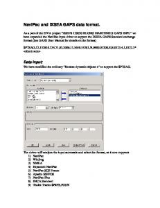
Software Breaks can be used with WinRiver. Start WinRiver in the Acquire mode. If you are in the Playback mode, click File, Acquire Mode. To open the Communications Settings dialog box, click Settings, Communications. Click the Properties button, General tab and select the Use Software Breaks box. The ADCP will use the "= = =" string instead of a break. Only Rio Grande firmware 10.05 and above, H-ADCP firmware 11.04 and above, and WorkHorse firmware 16.21 and above accepts this option.
Figure 5.
Software Break Setup in WinRiver
NOTE. In order for the software breaks to work, the CL command must be set to CL0 (see “CL - Battery Saver Mode,” page 44).
page 14
RD Instruments
WorkHorse Commands and Output Data Format
NOTE. Navigator ADCP/DVLs using the CP command (see “CP – Polled Mode,” page 37) send the “!” (exclamation) character for a soft break. To use the key in BBTalk, configure BBTalk for a normal break.
Expert Mode Purpose
Turns on or off the expert mode.
Format
expertoff, experton Recommended Setting. Use as needed.
Description
When the Expert Off command is used, it limits the amount of commands displayed on the help menu. When the expert mode is turned off, all commands are still available (to ensure software compatibility) but do not display. The Expert On command shows all of the available commands in the help menu.
Examples
See below.
expertoff Expert Mode is Off > experton Expert Mode is On >
OL - Features Purpose
Lists special firmware upgrades that are installed.
Format
OL Recommended Setting. Use as needed.
Description
Lists special features that are installed. See “Feature Upgrades,” page 5 for information on how to install additional capability in your WorkHorse.
Examples
See below.
>ol FEATURES --------------------------------------------------------------------Feature Installed --------------------------------------------------------------------Bottom Track Yes Water Profile Yes High Resolution Water Modes No Lowered ADCP No Waves Gauge Acquisition No See your technical manual or contact RDI for information on how to install additional capability in your WorkHorse.
P/N 957-6156-00 (March 2005)
page 15
WorkHorse Commands and Output Data Format
2.1
Compass Commands The main reason for compass calibration is battery replacement. Each new battery carries a different magnetic signature. The compass calibration algorithm corrects for the distortions caused by the battery to give you an accurate measurement.
2.1.1
Standard Compass Commands This section lists the most often used compass commands. AF – Field Calibrate Compass Purpose
Calibrates the compass to remove hard and soft iron effects.
Format
AF Recommended Setting. Use as needed. The compass must be calibrated if the batteries have been replaced.
Description
The built-in automated compass calibration procedures are similar to the alignment verification, but requires three rotations instead of one. The WorkHorse uses the first two rotations to compute a new calibration matrix and the third to verify the calibration. It will not accept the new matrix unless the calibration was carried out properly, and it asks you to verify that you want to use the new calibration if it is not as good as the previous calibration. While you are turning the WorkHorse for the two calibration rotations, the WorkHorse checks the quality of the previous calibration and displays the results. It compares these results with the results of the third calibration rotation. There are two compass calibrations to choose from; one only corrects for hard iron while the other corrects for both hard and soft iron characteristics for materials rotating with the ADCP. Hard iron effects are related to residual magnetic fields and cause single cycle errors while soft iron effects are related to magnetic permeability that distorts the earth’s magnetic field and causes double cycle errors. In general, the hard iron calibration is recommended because the effect of hard iron dominates soft iron. If a large double cycle error exists, then use the combined hard and soft iron calibration.
NOTE. For details on compass alignment, see the ADCP User’s Guide.
page 16
RD Instruments
WorkHorse Commands and Output Data Format
AR – Return to Factory Calibration Purpose
Returns to the factory calibration matrix.
Format
AR Recommended Setting. Use as needed.
Description
If the calibration procedure is not successful (AF-command), return your WorkHorse to the original factory calibration, by using the AR-command. Try using the AR-command if you have trouble calibrating your compass. In some circumstances, a defective compass calibration matrix can prevent proper calibration.
AX – Examine Compass Calibration Purpose
Used to verify the compass calibration.
Format
AX Recommended Setting. Use as needed.
Description
Compass calibration verification is an automated built-in test that measures how well the compass is calibrated. The procedure measures compass parameters at every 5º of rotation for a full 360º rotation. When it has collected data for all required directions, the WorkHorse computes and displays the results. Pay particular attention to the Overall Error.
Example
>AX
---------------------------------------------------------------------------RDI Compass Error Estimating Algorithm Press any key to start taking data after the instrument is setup. Rotate the unit in a plane until all data samples are acquired... rotate less than 5°/sec. Press Q to quit. N NE E SE S SW W NW N ^ ^ ^ ^ ^ ************************************************************************ Accumulating data ... Calculating compass performance ... >>> Total error:
1.5°
TE. When using VmDas with Workhorse ADCPs that do not support bottom tracking, the BP command will fail on those Workhorses. This is OK if the ADCP Setup Options generates the BP command, but a failed command in the command file aborts processing of the command file. The BP command should be removed from the command file in this case. See the VmDas User's Guide for details.
P/N 957-6156-00 (March 2005)
page 21
WorkHorse Commands and Output Data Format
BX – Maximum Tracking Depth Purpose
Sets the maximum tracking depth in bottom-track mode.
Format
BXnnnn
Range
nnnn = 10 to 65535 decimeters (meters x 10)
Default
BX5500 (150 kHz), BX2000 (300 kHz), BX1250 (600 kHz), BX0450 (1200 kHz), BX0150 (2400 kHz) Recommended Setting. Set BX to a depth slightly greater than the expected maximum depth.
page 22
Description
The BX-command sets the maximum tracking depth used by the ADCP during bottom tracking. This prevents the ADCP from searching too long and too deep for the bottom, allowing a faster ping rate when the ADCP loses track of the bottom. If the bottom-track water reference layer is in use (BK > 0), BX must be greater than the Far Layer Boundary (BLmmm,nnnn,ffff), or the ADCP sends Error Code 012.
Example
If you know the maximum depth in the deployment area is 20 meters (200 decimeters), set BX to a value slightly larger than 200 dm, say 210 dm, instead of the default 1250 dm. Now if the ADCP loses track of the bottom, it will stop searching for the bottom at 210-dm (21 m) rather than spend time searching down to 125-dm (125 m), which is the maximum bottomtracking range.
RD Instruments
WorkHorse Commands and Output Data Format
2.2.2
Expert Bottom Track Commands This section lists the less often used Bottom Track commands. BA - Evaluation Amplitude Minimum Purpose
Sets the minimum value for valid bottom detection.
Format
BAnnn
Range
nnn = 1 to 255 counts
Default
BA30 Recommended Setting. The default setting for this command is recommended for most applications.
Description
BA sets the minimum amplitude of an internal bottom-track filter that determines bottom detection. Reducing BA increases the bottom-track detection range, but also may increase the possibility of false bottom detections.
BB – High Bandwidth Maximum Depth Purpose
This command lets the user define the depth at which the ADCP switches between 25% and 50% bandwidth.
Format
BBnnnn
Range
nnnn = 0 to 9999 dm
Default
BB0640 (150 kHz), BB0320 (300 kHz), BB160 (600 kHz), BB60 (1200 kHz), BB20 (2400 kHz) Recommended Setting. The default setting for this command is recommended for most applications.
Description
This command lets the user define the depth at which the ADCP switches between 25% and 50% bandwidth. A setting of zero disables 50% bandwidth. A setting of 9999 disables 25% bandwidth.
P/N 957-6156-00 (March 2005)
page 23
WorkHorse Commands and Output Data Format
BC - Correlation Magnitude Minimum Purpose
Sets minimum correlation magnitude for valid velocity data.
Format
BCnnn
Range
nnn = 0 to 255 counts
Default
BC220 Recommended Setting. The default setting for this command is recommended for most applications.
Description
Sets a minimum threshold for good bottom-track data. The ADCP flags as bad any bottom-track data with a correlation magnitude less than this value.
NOTE. A count value of 255 is a perfect correlation (i.e. solid target)
BD - Delay before Reacquire Purpose
Sets a delay period before trying to reacquire the bottom.
Format
BDnnn
Range
nnn = 0 to 999 ensembles
Default
BD0 Recommended Setting. The default setting for this command is recommended for most applications.
page 24
Description
BD sets the number of ADCP ensembles to wait after losing the bottom before trying to track it again. In effect, BD reduces the number of bottom-track pings and increases the water-track ping rate when the bottom becomes out of range. If the ADCP loses track of the bottom, it immediately transmits a series of search pings. If the ADCP can not find the bottom after 16 pings, it will then wait BD ensembles before starting the search sequence again.
Examples
If BD = 10, the ADCP waits 10 ADCP ensembles after the automatic search sequence before beginning the search sequence again. If BD = 0 (default), the ADCP continually tries to find the bottom.
RD Instruments
WorkHorse Commands and Output Data Format
BE - Error Velocity Maximum Purpose
Sets maximum error velocity for good bottom-track data.
Format
BEnnnn
Range
nnnn = 0 to 9999 mm/s
Default
BE1000 Recommended Setting. The default setting for this command is recommended for most applications. CAUTION. The default setting is set purposely high and as a result effectively disabled. We recommend extreme caution and testing before changing this setting. Data rejected by this command is lost and cannot be regained.
Description
The ADCP uses this parameter to determine good bottomtrack velocity data. If the error velocity is greater than this value, the ADCP marks as bad all four beam velocities (or all four coordinate velocities, if transformed). If three beam solutions are allowed (see “EX – Coordinate Transformation,” page 51) and only three beams are good, then the data is accepted since four good beams are needed for error velocity calculation.
BF - Depth Guess Purpose
Sets a “best-guess” of expected bottom range for internal calculations.
Format
BFnnnnn
Range
nnnnn = 1 to 65535 dm (0 = automatic)
Default
BF0 Recommended Setting. The default setting for this command is recommended for most applications.
Description
When set to a non-zero value, the ADCP transmits a fixed pulse based on a given bottom range. This is useful for applications with fixed range bottoms. The command reduces the amount of time the ADCP uses to search for the bottom if lost.
CAUTION. If improperly set, the ADCP may not bottom-track at all if the bottom range varies from the input range.
P/N 957-6156-00 (March 2005)
page 25
WorkHorse Commands and Output Data Format
BI - Gain Switch Depth Purpose
Selects the maximum vertical distance from the transducer to the bottom at which the ADCP operates at low gain.
Format
BInnn
Range
nnn = 0 to 999 meters
Default
BI040 (150 kHz), BI020 (300 kHz), BI010 (600 kHz), BI005 (1200kHz), BI001 (2400kHz) Recommended Setting. The default setting for this command is recommended for most applications.
Description
When the vertical range to the bottom is less than BI, the unit operates in low gain. When the vertical range is greater than BI, internal logic determines which gain (low or high) is optimal. In high backscatter areas, it may be necessary to raise this setting in order to detect bottom throughout the range of the system.
BK - Water-Mass Layer Mode Purpose
Selects the ping frequency of the water-mass layer ping
Format
BKn
Range
n = 0 to 3
Default
BK0 Recommended Setting. The default setting for this command is recommended for most applications.
Description
page 26
BK selects how often the ADCP performs a water-mass layer ping while bottom tracking. The number of water-mass layer pings per ensemble is dependent on the BP-command (bottom pings per ensemble) and this command setting. Use the BLcommand to set the location of the water-mass layer.
Table 4:
Water-Mass Reference-Layer Modes
Command
Description
BK0
Disables the water-mass layer ping.
BK1
Sends a water-mass layer ping after every bottom-track ping (exception if BW > 0, see BW command). Note; the BW command is only available for WorkHorse Navigator ADCP/DVLs.
BK2
Sends a water-mass layer ping after every bottom-track ping that is unable to find the bottom.
BK3
Disables the bottom-track ping and enables the water-mass ping.
RD Instruments
WorkHorse Commands and Output Data Format
BL - Water-Mass Layer Parameters Purpose
Sets bottom-track water-mass layer boundaries and minimum layer size.
Format
BLmmm,nnnn,ffff
Range
mmm = Minimum Layer Size (0 - 999 decimeters) [meters x 10] nnnn = Near Layer Boundary (0 - 9999 decimeters) [meters x 10]
ffff = Far Layer Boundary (0 - 9999 decimeters) [meters x 10] Default
BL320,640,960 (150 kHz), BL160,320,480 (300 kHz), BL80,160,240 (600 kHz), BL40,60,100 (1200kHz), BL20,20,40 (2400kHz) Recommended Setting. The default setting for this command is recommended for most applications.
Description
The BL-command sets a water-mass layer. You can use this layer as a reference point when the bottom is out of range or is incorrect. Water-mass layer output data are available when both BK - Water-Mass Layer Mode and BP - Bottom-Track Pings Per Ensemble are nonzero values, and the bottom must be at least the Minimum Layer Size + Near Layer Boundary + 20% of the reported depth away from the transducer. The Far Layer Boundary (ffff) must be less than the maximum profiling distance or the ADCP sends Error Code 011. The user-defined water-mass layer is used unless the layer comes within 20% of the water boundary (sea floor for downlooking systems; surface for up-looking systems). As the user-defined water-mass layer comes within 20% of the boundary (Figure 6, B), the layer compresses in size until the minimum water-mass layer size is reached. When the boundary moves closer to the transducer (Figure 6, C), no water mass ping will be sent.
NOTE. The water-mass layer is operational only if BP > zero and BK > zero.
Figure 6.
Water-Mass Layer Processing
P/N 957-6156-00 (March 2005)
page 27
WorkHorse Commands and Output Data Format
BM - Bottom Track Mode Purpose
Sets the Bottom Track mode.
Format
BMn
Range
n = 4, 5, (see description), 6 (only available for Navigator ADCP/DVLs), 7 (available as a feature upgrade for 1200kHz WorkHorse and Rio Grande ADCPs with firmware version 16.19/10.11)
Default
BM5 (150, 300, 600, and 1200 kHz), BM6 (2400 kHz) Recommended Setting. The default setting for this command is recommended for most applications.
Description
See below
Bottom Track Mode 4 Bottom Track Mode 4 uses the correlation side-peak position to resolve velocity ambiguities. It lengthens the lag at a predetermined depth to improve variance. Bottom Track Mode 5 Bottom Track Mode 5 is similar to Bottom Track Mode 4, but has a lower variance in shallow water by a factor of up to four. In very shallow water at slow speeds, the variance is lower by a factor of up to 100. Bottom Track Mode 5 also has a slightly slower ping rate than Bottom Track Mode 4. NOTE. Bottom Mode 5 (default setting) will shift to Bottom Mode 4 if the conditions warrant.
The ADCP limits searching for the bottom to the value set by the BX-command (max bottom tracking altitude) + 0.5 transmit length. This allows a faster ping rate when the bottom altitude is close to the BX-command setting. Table 5:
page 28
BM4/BM5 Minimum Tracking Depths
Frequency (kHz)
BM4/BM5 Minimum Tracking Depths (m)
150
2.0
300
1.5
600
1.0
1200
0.8
RD Instruments
WorkHorse Commands and Output Data Format
Bottom Track Mode 6 NOTE. Bottom Mode 6 is available for Navigator ADCP/DVLs only.
Bottom Mode 6 is a very simple mode. There is no ambiguity resolving, which allows Bottom Mode 6 to operate in Narrower Bandwidths than the standard bottom tracking. Bottom Mode 6 operates in 12.5% and 6.25% Bandwidths. The need for reduced bandwidth could arise to reduce interference or detectability. Bottom Mode 6, by reducing bandwidth, also reduces sample rate. This results in noisier data. Along with noisy data, comes the complexity of properly configuring the mode. Improper configuration can result in wild (unreasonable) data. If you are interested in using this mode, please request a copy of Field Service Application Note FSA-012 Configuring Bottom Mode 6 (available for download at www.rdinstruments.com, Customer Support page). Bottom Track Mode 7 NOTE. Bottom Mode 7 is a feature upgrade for 1200kHz Navigators, WorkHorse and Rio Grande ADCPs (see “Feature Upgrades,” page 5). Contact RDI for information on how to install this capability in your WorkHorse. Firmware versions prior to version 16.26 allowed Bottom Mode 7 for 600kHz ADCPs.
Bottom Mode 7 has several advantages over BM5 in slow moving, shallow water applications. Bottom Mode 7 was developed for even shallower applications than Mode 5 yet it retains bottom Mode 5’s very precise velocity measurement (see Table 6, page 30). It addresses other shallow water issues such as bottom detection in the presence of high backscatter water, signal level control despite a wide range of bottom backscatter for various applications, and transmit/receive interference when beam depths are substantially different. Bottom Mode 7 pings at a slower rate than Bottom Mode 5 (1/3 the rate of BM5) and the precision of its velocity measurement degrades at velocities higher than 0.2m/s. If you are interested in using this mode, please request a copy of Field Service Application Note FSA-015 Shallow Water Bottom Tracking Mode 7 (available for download at www.rdinstruments.com, Customer Support page).
P/N 957-6156-00 (March 2005)
page 29
WorkHorse Commands and Output Data Format
Table 6:
BM7 Minimum Tracking Depths
Freq
Min Tracking Depths
600kHz
0.6m
1200kHz
0.3m
BN – Speed Log Hold/Drop Control Purpose:
Controls the behavior of the distance measure calculation when Bottom Track is lost.
NOTE. The BN command is available only for WorkHorse Navigator ADCP/DVLs.
Format:
BNx,y
Range:
x = 0 to 1 y = 0 to 999 seconds
Default:
BN25 Recommended Setting. The default setting for this command is recommended for most applications.
Description:
The BN command governs the behavior of the earth referenced distance measurement calculation in the PD6 data format when the ADCP can’t get a lock on the bottom. The y parameter represents a timeout period during which zero is used for the current velocity measurement in the equation shown in the BO command. After the expiration of the y timeout, the behavior is governed by the x parameter. If x is zero, then the accumulated distance is set to zero. If x is one, then the accumulated distance is maintained at its current value until the ADCP achieves bottom lock.
BO - Distance Measure Filter Constant Purpose:
Sets the value of the filter constant used by the distance measurement calculation in PD6.
NOTE. The BO command is available only for WorkHorse Navigator ADCP/DVLs.
Format:
BOk
Range:
k = 0 to 100
Default:
BO25 Recommended Setting. The default setting for this command is recommended for most applications.
page 30
RD Instruments
WorkHorse Commands and Output Data Format
Description:
When calculating the earth referenced distance data for output in the PD6 data format, the ADCP applies a simple exponential filter to the velocity measurements before calculating the distance. The velocity used to calculate the distance is given by the following equation: v = (k • vnew + (k –100) • vold) / 100 Where vnew is the current velocity measurement, vold is the value of v calculated for the previous distance calculation, and k is the value of the BO command. Setting k to 100 effectively disables the exponential filter.
BR - Resolution Purpose
Sets the vertical depth resolution.
Format
BRn
Range
n = 0 to 2 (see description)
Default
BR0 Recommended Setting. The default setting for this command is recommended for most applications.
Description
BR sets the vertical depth resolution as a percentage of the overall range detected. The lower the resolution, the finer the depth reading. With BR0 set, if you had a depth of 100 meters, then the depth would read 100 meters until you passed 104 meters. If you had BR2 set, then it would change when you reached 101 meters. Setting a higher resolution (e.g. 1%) results in longer ping times. BR0 = 4%
BR1 = 2%
BR2 = 1%
Resolution Setting Limitations:
1) Minimum RSSI Bin Size – The RSSI sampling interval cannot be smaller than the minimum RSSI bin size (for example, 5 cm for a 1200 kHz system). This means that you get the resolution that you command in % or 5 cm (for the above example) - whichever is larger. The minimum RSSI bin sizes vary with system frequency according to the following table: Frequency
Min RSSI Bin Size
150
37 cm
300
18 cm
600
9 cm
1200
5 cm
2) BM5 Low Altitude Minimum RSSI Bin Size -- This limitation affects only Bottom Mode 5 operation below the following altitudes:
P/N 957-6156-00 (March 2005)
page 31
WorkHorse Commands and Output Data Format
• • • •
150 kHz -- 20 meters -- the resolution becomes 63 cm 300 kHz -- 10 meters -- the resolution becomes 16 cm 600 kHz -- 5 meters -- the resolution becomes 8 cm 1200 kHz -- 2.5 meters -- the resolution becomes 7.8 cm
BS - Clear Distance Traveled Purpose
Clears internal distance traveled accumulators.
Format
BS Recommended Setting. Use as needed.
Description
Distance traveled is calculated and output in DVL output formats (PD5 and PD6). The accumulator is zeroed on or by using this command in the manual ensemble cycling mode.
BV – Mode 7 Parameters Purpose
Controls the behavior of Bottom Track Mode 7.
Format
BV aaaaa, bbb, c
Range
aaaaa = 0 to 65535 bbb = 0 to 255 c = 0 or 1 (0 = Off, 1 = On)
Default:
BV10, 250, 0 (1200kHz), BV20,250,0 (600kHz) Recommended Setting. The default setting for this command is recommended for most applications.
Description:
The first parameter sets the depth at which the bottom will be searched. It avoids locking onto ringing (if any) or very high backscatter water near the transducer. The second parameter controls the correlation threshold for ambiguity resolving. A lower, fixed correlation threshold is used to determine if a lag’s velocity estimate is satisfactory. The last parameter controls whether short lag velocity estimates are output in the event the longer lag ambiguity cannot be resolved because one or more of the short lag velocity estimates have too low a correlation. If this parameter is a one, then the average of the four short lag estimates that are above a lower, fixed correlation threshold will be used. If this parameter is a zero, then no velocity will be output for this case.
page 32
RD Instruments
WorkHorse Commands and Output Data Format
NOTE. A count value of 255 is perfect correlation.
BW - Water Reference Interval Purpose
This parameter controls the number of bottom track pings between water reference pings per ensemble. NOTE. The BW command is available only for WorkHorse Navigator ADCP/DVLs.
Format
BWn
Range
n = 0 to 65535
Default
BW00001 Recommended Setting. The default setting for this command is recommended for most applications.
Description
The BW command sets the ratio of water reference pings to bottom track pings. Using this command allows you to control how often the water reference ping is done, and therefore the total number of water reference pings per ensemble.
Example
If you wanted to do two water reference pings in an ensemble and BW = 5 (BW5), BP = 10 (BP10), and BK = 1 (BK1), then the ADCP will perform five bottom pings, one water reference ping, five bottom pings, then one water reference ping.
NOTE. The BK-command must be set to one (BK1) for this command to work.
BZ - Coherent Ambiguity Velocity Purpose
Sets the Bottom-Track Mode 5 ambiguity velocity.
Format
BZnnn
Range
nnn = 0 to 999 cm/s radial
Default
BZ004 Recommended Setting. The default setting for this command is recommended for most applications.
Description
The BZ-command selects the ambiguity velocity used by the bottom-track ping in shallow water when bottom-track Mode 5 is in use.
P/N 957-6156-00 (March 2005)
page 33
WorkHorse Commands and Output Data Format
2.3
Control System Commands The WorkHorse uses the following commands to control certain system parameters.
2.3.1
Standard Control System Commands This section lists the most often used Control System commands. CB - Serial Port Control Purpose
Sets the RS-232/422 serial port communications parameters (Baud Rate/Parity/Stop Bits).
Format
CBnnn
Range
nnn = baud rate, parity, stop bits (see description)
Default
CB411 Recommended Setting. The default setting for this command is recommended for most applications.
Description
Table 7:
The WorkHorse and your external device (dumb terminal, computer software) MUST use the same communication parameters to talk to each other. After you enter valid CB parameters, the WorkHorse responds with a “>” prompt. You may now change the external device’s communication parameters to match the WorkHorse parameters before sending another command. Serial Port Control
Baud Rate
Parity
Stop Bits
1 = 1200
1 = None (Default)
1 = 1 Bit (Default)
2 = 2400
2 = Even
2 = 2 Bits
3 = 4800
3 = Odd
4 = 9600 (Default)
4 = Low (Space, logical 0)
5 = 19200
5 = High (Mark, logical 1)
0 = 300
6 = 38400 7 = 57600 8 = 115200
Setting The Baud Rate In The WorkHorse. The WorkHorse can be set to
communicate at baud rates from 300 to 115200. The factory default baud rate is always 9600 baud. The baud rate is controlled via the CB-command. The following procedure explains how to set the baud rate and save it in the
page 34
RD Instruments
WorkHorse Commands and Output Data Format
WorkHorse. This procedure assumes that you will be using the program BBTalk that is supplied by RD Instruments. a. Connect the WorkHorse to the computer and apply power (see the appropriate ADCP User's Guide). b. Start the BBTalk program and establish communications with the ADCP. Wakeup the Workhorse by sending a break signal with the End key. c. Send the command CR1 to place the WorkHorse in the factory default setup. d. Send the CB-command that selects the baud rate you wish. The following are the typical CB-command settings for different baud rates with no parity and 1 stop bit: Table 8:
Baud Rate
BAUD RATE
CB-command
300
CB011
1200
CB111
2400
CB211
4800
CB311
9600
CB411 (Default)
19200
CB511
38400
CB611
57600
CB711
115200
CB811
e. In BBTalk, press F5 and change the settings to match your CB command settings. Press OK to exit the communication setup screen. f. Send the command CK to save the new baud rate setting. g. Click File, Close to exit the terminal window. The Workhorse is now set for the new baud rate. The baud rate will stay at this setting until you change it back with the CB-command. NOTE. If you send a BREAK before changing the external device’s communication parameters, the WorkHorse returns to the communication parameters stored in non-volatile memory (user settings).
P/N 957-6156-00 (March 2005)
page 35
WorkHorse Commands and Output Data Format
CF - Flow Control Purpose
Sets various WorkHorse data flow-control parameters.
Format
CFnnnnn
Range
Firmware switches (see description)
Default
CF11111 Recommended Setting. The default setting for this command is recommended for most applications.
Description
The CF-command defines whether the WorkHorse: generates data ensembles automatically or manually; generates pings immediately or manually; sends serial output data in binary or Hex-ASCII format; sends or does not send output data to the serial interface; sends or does not send data to the recorder (if installed).
NOTE. The VmDas program sets the WorkHorse to a manual ensemble mode (CF01110) so that it controls when the ensemble occurs.
Table 9:
page 36
Flow Control
Command
Description
CF1xxxx
Automatic Ensemble Cycling – Automatically starts the next data collection cycle after the current cycle is completed. Only a can stop this cycling.
CF0xxxx
Manual Ensemble Cycling – Enters the STANDBY mode after transmission of the data ensemble, displays the “>” prompt and waits for a new command.
CFx1xxx
Automatic Ping Cycling – Pings immediately when ready.
CFx0xxx
Manual Ping Cycling – Sends a < character to signal ready to ping, and then waits to receive an before pinging. The sent to the WorkHorse is not echoed. This feature lets you manually control ping timing within the ensemble.
CFxx2xx
Hex-ASCII Data Output, Carriage Return-Linefeed delimited -- Sends the ensemble in readable hexadecimal-ASCII format with a Carriage Return-Linefeed at the end of each ensemble, if serial output is enabled (see below).
CFxx1xx
Binary Data Output – Sends the ensemble in binary format, if serial output is enabled (see below).
CFxx0xx
Hex-ASCII Data Output – Sends the ensemble in readable hexadecimal-ASCII format, if serial output is enabled (see below).
CFxxx1x
Enable Serial Output – Sends the data ensemble out the RS-232/422 serial interface.
CFxxx0x
Disable Serial Output – No ensemble data are sent out the RS-232/422 interface.
CFxxxx1
Enable Data Recorder – Records data ensembles on the recorder (if installed).
CFxxxx0
Disable Data Recorder – No data ensembles are recorded on the recorder.
Example
CF01010 selects manual ensemble cycling, automatic ping cycling, Hex-ASCII data output, enables serial output, and disables data recording.
RD Instruments
WorkHorse Commands and Output Data Format
CK - Keep Parameters Purpose
Stores present parameters to non-volatile memory.
Format
CK Recommended Setting. Use as needed.
Description
CK saves the present user command parameters to nonvolatile memory on the CPU board. The WorkHorse maintains data stored in the non-volatile memory (user settings) even if power is lost. It does not need a battery. You can recall parameters stored in non-volatile memory with the CR0command.
CP – Polled Mode Purpose:
Allows the unit to be polled for data.
NOTE. The CP command is not available for Navigator ADCP/DVLs.
Format
CPn
Range
n = 0 (Off), 1 (On)
Default
CP0 Recommended Setting. The default setting for this command is recommended for most applications.
Description
Table 10: Command
The CP command allows a unit to be polled for data. Setting the CP command to one places the ADCP into a mode where it doesn’t sleep. Instead the ADCP stays awake between pings listening for certain commands (and drawing more power). Polled mode is only recommended for deployments where shore power can be provided. The commands the ADCP responds to while in polled mode are shown in Table 10. Polled Mode Commands Description
!
Execute a Break reset
+
Increment internal clock by 1 second
-
Decrement internal clock by 1 second
D
Dump the last ensemble
E
Print the current ensemble number
T
Print the current time
P/N 957-6156-00 (March 2005)
page 37
WorkHorse Commands and Output Data Format
The commands are not echoed and they don’t need to be followed by a CR/LF pair. These commands are only available when CP = 1. NOTE. Enabling polled mode disables the battery saver feature. Do not enable this mode when running from batteries.
CQ – Transmit Power Purpose
Allows the transmit power to be adjusted. NOTE. The CQ command is not available for Navigator ADCP/DVLs.
Format
CQnnn
Range
nnn = 0, or 1 to 255 (0 = Low, 1 to 255 = High)
Default
CQ255 Recommended Setting. The default setting for this command is recommended for most applications.
Description
Allows the transmit power to be set high or low. This only affects 75 and 150kHz systems.
CR – Retrieve Parameters Purpose
Resets the WorkHorse command set to factory settings.
Format
CRn
Range
n = 0 (User), 1 (Factory) Recommended Setting. Use as needed.
Description
Table 11:
page 38
The WorkHorse automatically stores the last set of commands used in RAM. The WorkHorse will continue to be configured from RAM unless it receives a CR-command or until the RAM loses its power. Retrieve Parameters
Format
Description
CR0
Loads into RAM the command set last stored in non-volatile memory (user settings) using the CK-Command.
CR1
Loads into RAM the factory default command set stored in ROM (factory settings).
RD Instruments
WorkHorse Commands and Output Data Format
NOTE. CR keeps the present baud rate and does not change it to the value stored in non-volatile memory or ROM. This ensures the WorkHorse maintains communications with the terminal/computer.
CS – Start Pinging (Go) Purpose
Starts the data collection cycle (same as the Tab key).
Format
CS Recommended Setting. Use as needed. Use WinSC/VmDas/WinRiver to create the command file. The CS command will be added to the end of the command file or sent by the software.
Description
Use CS (or the Tab key) to tell the WorkHorse to start pinging its transducers and collecting data as programmed by the other commands. If the TF-command is set (time of first ping), the WorkHorse waits until it reaches the TF time before beginning the data collection cycle.
NOTES. 1. After a CS-command is sent to the WorkHorse, no changes to the commands can occur until a is sent. 2. If you try to record data (CFxxxx1), and the recorder is full, the WorkHorse will not start pinging and will return a RECORDER NOT READY message.
CX – Low Latency Trigger Enable Purpose Format Range Default
Enables or disables the low latency trigger. CXn n = 0 (off), 1 (on) CX0 Recommended Setting. The default setting for this command is recommended for most applications. For more information on using the CX command, see FSA-018 (available on www.rdinstruments.com).
Description
Turning on the Low Latency Trigger functionality allows the Workhorse to ping within ~300µs of the rising edge of the trigger. The trigger needs to be on a differential signal pair that starts with a rising edge on one signal line and a falling edge on the other signal line.
CAUTION. The CX command inhibits the ability of the Workhorse to sleep and conserve power. Use CX1 only when power consumption is not an issue.
P/N 957-6156-00 (March 2005)
page 39
WorkHorse Commands and Output Data Format
NOTE. If CX1 is used, the CL command must be set to CL0 (see “CL Battery Saver Mode,” page 44).
CZ – Power Down WorkHorse Purpose
Tells the WorkHorse to power down.
Format
CZ Recommended Setting. Use as needed.
Description
Sending the CZ-command powers down the WorkHorse. WorkHorse processing is interrupted and the WorkHorse goes in the STANDBY mode (RAM is maintained).
NOTES. 1. When powered down using the CZ-command, the WorkHorse still draws up to 30µa, but wakes up periodically (every 8 to 12 hours) for a few seconds to maintain RAM. 2. This command should be used whenever batteries have been installed and you do not send commands to start a deployment. If you do not use the CZ-command, the WorkHorse will draw up to 50 milli-amps of current. A new battery will be discharged in a few days. 3. Performance and testing commands (i.e. AF, PA, PT, RB, and RY) override the battery saver functions. For example, using the RY-command to recover data from the ADCP while on battery power will disable the automatic power saver mode. If a CZ-command is not used after all data has been recovered, the ADCP will remain in the command mode. RDI recommends disconnecting the batteries and using the AC power adapter while testing or recovering data.
page 40
RD Instruments
WorkHorse Commands and Output Data Format
2.3.2
Expert Control System Commands This section lists the less often used Control System commands. CA - Control Periodic Output Purpose
Sets the periodic Output Interval in tenths of seconds. NOTE. The CA command is only available for Navigator ADCP/DVLs.
Format
CAnnn
Range
nnn = 0, 10 to 600 tenths of seconds
Default
CA0 Recommended Setting. The default setting for this command is recommended for most applications.
Description
This command sets the periodic output interval in tenths of seconds. Leaving CA at its default of zero disables periodic output. The minimum interval is 1 second and the maximum is 1 minute. This command depends on the triggering being enabled (See “CX – Low Latency Trigger Enable,” page 39). The CA command doesn’t set an output; it sets an output rate. It allows the user to set a periodic rate of data output. It is only useful when the CX command is set to CX1. This gives the user the ability to synchronize pings to an external source, while outputting data at a set rate.
CAUTION. Setting the CA command to a non-zero number with the CX command set to 0 will result in non-function of the ADCP.
CC - Choose External Devices Purpose
Selects the external devices used by the ADCP.
Format
CC abc def ghi
Range
Firmware switches (see description)
Default
CC 000 000 000 Recommended Setting. The default setting for this command is recommended for most applications.
Description
The CC command uses firmware switches to tell the ADCP the types of data to collect. Setting a bit to one tells the ADCP to collect that data type. The bits are described as follows:
P/N 957-6156-00 (March 2005)
page 41
WorkHorse Commands and Output Data Format
a = Reserved
d = Reserved
g = Reserved
b = Reserved
e = Reserved
h = Reserved
c = Reserved
f = Reserved
i = Seabird MicroCAT
Example
CC 000 000 001 tells the ADCP to collect Seabird MicroCAT data.
NOTE. The data ID for the MicroCAT data is 0800h.
CD – Serial Data Out Purpose
Selects the serial data types collected by the ADCP. NOTE. The CD command is not available for Navigator ADCP/DVLs.
Format
CD abc def ghi
Range
Firmware switches - Setting a bit to one tells the ADCP to collect that data type. The bits are described as follows.
Default
a = Velocity
d = Percent good
g = Reserved
b = Correlation
e = Status
h = Reserved
c = Echo Intensity
f = Reserved
I = Reserved
CD 000 000 000 Recommended Setting. The default setting for this command is recommended for most applications.
Description
The CD command functions like the WD command, except it controls data output serially. If CD is left in the default state (no data selected), the WD setting controls serial and recorded data. If CD is set to anything else, the CD setting controls data output serially, while the WD command controls what is written to the recorder.
CE - Retrieve Most Recent Data Ensemble Purpose:
Output the most recent data ensemble.
NOTE. The CE command is not available for Rio Grande, H-ADCP, and Navigator ADCP/DVLs.
page 42
Format:
CE
Description:
CE outputs the most recent data ensemble via the serial communications port in either binary or Hex-ASCII mode as
RD Instruments
WorkHorse Commands and Output Data Format
specified by the CF command. The WorkHorse ADCP buffers the last ensemble collected in RAM just prior to it being sent to the recorder or being output to the serial port of the ADCP. Notes:
To retrieve data with the CE command the WorkHorse ADCP must be in command mode, i.e. a break has been sent to stop the automatic ensemble mode, or the prompt has been returned in the manual ensemble mode. No data is available in the buffer until a deployment has been started (CS command has been sent) and the first ensemble has been completed.
Retrieving the Most Recent Ensemble
The following example assumes that the WorkHorse ADCP has already been deployed and therefore is actively collecting data either on the internal recorder, out the serial port, or both. The following steps will provide the example of how to recover and capture the most recent ensemble. a. Open the RDI software program BBTalk. b. Configure the communications for the port that the WorkHorse ADCP is connected to. c. Click the B on the toolbar to send a break to the ADCP. d. Press the F3 key to turn on the capture feature in BBTalk. Enter a name and path for the file you are about to create. e. Type the command CE and press enter. The data from the last ensemble will be transferred from the ADCP into the BBTalk program and captured to the file you created in Step “d”. f. Press the F3 key to close the file. g. Verify the file contains a valid ensemble of data and continue to step “h”. h. Type the command CS and press enter. The ADCP will continue its deployment. Depending on the setting of the RI command, the ADCP will either append to the existing deployment file (starting at ensemble 1) or it will open a new deployment file. NOTE. If the RI command has been set to disable the auto increment (RI0) of the deployment file then you can at this time decide to close the current data file and start a new file by sending the RDOPEN command. Sending the RDCLOSE command will close the file only and a new file will not be opened until Step “i” is performed and the ADCP collects 8kbytes of data.
P/N 957-6156-00 (March 2005)
page 43
WorkHorse Commands and Output Data Format
CH – Suppress Banner Purpose
Prevents the unit from sending the wakeup message. NOTE. The CH command is not available for Rio Grande, H-ADCP, and Navigator ADCP/DVLs.
Format
CHn
Range
n = 0 (display banner), or 1 (suppress banner)
Default
CH0 Recommended Setting. The default setting for this command is recommended for most applications.
Description
If CH1 is saved as part of the User Command Set, the unit will not output a banner on wakeup. The unit will still output the “>” prompt.
CAUTION. Suppression of the wakeup banner may cause some RDI software to fail or function erratically.
CI – Instrument ID Purpose
Sets the ID for the ADCP. NOTE. The CI command is not available for Rio Grande, H-ADCP, and Navigator ADCP/DVLs.
Format Range Default
CInnn nnn = 0 to 255 CI0 Recommended Setting. The default setting for this command is recommended for most applications.
Description
This command allows the user to uniquely identify a single ADCP in a network of up to 256 ADCPs. The value to which this command is set will be output in the PD12 output format.
NOTE. This command has no effect if PD is set to other than PD12.
CL - Battery Saver Mode Purpose
page 44
Determines whether the ADCP will attempt to conserve power by sleeping between pings.
RD Instruments
WorkHorse Commands and Output Data Format
NOTE. The CL command is only available for Rio Grande, Navigator ADCP/DVLs, and WorkHorse ADCPs with 16.21 or higher firmware.
Format Range Default
CLn n = 0 to 1 (Sleep Between Pings (0 = No, 1 = Yes) CL1 Recommended Setting. The default setting for this command is recommended for most applications.
Description
CL0 means the ADCP will not make any attempt to conserve power. Setting the CL command to CL1 means the ADCP will attempt to conserve power by going to sleep at every opportunity.
NOTE. In order for software breaks to work, the CL-command must be set to CL0 (see “Break,” page 14).
CM - Master Purpose
Deprecated. For Lowered ADCP use, see the “Lowered ADCP Commands,” page 110 and the Lowered ADCP User’s Guide. NOTE. The CM command is not available for Navigator ADCP/DVLs.
CN - Save NVRAM to Recorder Purpose:
Saves the contents of NVRAM to the recorder at the end of a deployment.
Format
CNn
Range
n = 0 (On), 1 (Off)
Default
CN1 Recommended Setting. The default setting for this command is recommended for most applications.
Description
The CN command allows the contents of the NVRAM (approx. 8k bytes) to be written to the recorder as part of the deployment record. This can be useful for troubleshooting purposes.
P/N 957-6156-00 (March 2005)
page 45
WorkHorse Commands and Output Data Format
CT - Turnkey Operation Purpose
Allows the ADCP to initialize to predefined parameters and start pinging immediately after power is applied. NOTE. The CT command is only available for Navigator ADCP/DVLs.
Format
CTn
Range
n = 0 to 1 (0 = Off, 1 = Turnkey)
Default
CT1
Description
Setting the CT command to CT1 lets the ADCP automatically initialize to a predefined command set during any power up. To place the ADCP in turnkey mode, you must first set all other commands to the desired configuration. You must then send the CT1 and CK commands to save this configuration. When power is cycled, the ADCP will start up with the desired configuration and begin the data collection process. You can interrupt (not remove) this mode by sending a . This will place the ADCP in the command mode, ready to accept inputs. Cycling the power, however, will again start the data collection process. To turn off the turnkey mode, first send a to the ADCP. Now send the CT0 and CK commands to save this configuration. When power is cycled, the ADCP will NOT begin the data collection process.
page 46
RD Instruments
WorkHorse Commands and Output Data Format
CY - Clear Error Status Word Purpose
Clears the Error Status Word (ESW) stored in EEPROM on the CPU. The ESW is updated whenever an error occurs.
Range
0, 1
Format
Use the CY1 command to display the ESW value or CY0 to clear the ESW. Recommended Setting. Use as needed.
Description Table 12:
CY1 displays the active ESW value, which is a 32-bit value displayed in Hex ASCII. Error Status Word
ESW
Description
0x00000001
Bus Error Exception occurred.
0x00000002
Address Error Exception occurred.
0x00000004
Illegal Inst Exception occurred.
0x00000008
Zero Divide Exception occurred.
0x00000010
Emulator Exception occurred.
0x00000020
Unassigned Exception occurred.
0x00000040
Watchdog restart occurred.
0x00000080
Screen Save power down occurred.
0x00000100
Currently pinging.
0x00000200
Unused
0x00000400
Unused
0x00000800
Unused
0x00001000
Unused
0x00002000
Unused
0x00004000
Cold wakeup occurred.
0x00008000
Unknown wakeup occurred.
0x00010000
Clock read failure occurred.
0x00020000
Unexpected Alarm.
0x00040000
Clock jump forward.
0x00080000
Clock jump backward.
0x00100000
Unused
0x00200000
Unused
0x00400000
Unused
0x00800000
Unused
Continued Next Page
P/N 957-6156-00 (March 2005)
page 47
WorkHorse Commands and Output Data Format
Table 12:
Error Status Word (continued)
ESW
Description
0x01000000
Unused
0x02000000
Unused
0x04000000
Unused
0x08000000
Power Fail (Unrecorded)
0x10000000
Spurious level 4 interrupt (DSP).
0x20000000
Spurious level 5 interrupt (UART).
0x40000000
Spurious level 6 interrupt (CLOCK).
0x80000000
Level 7 interrupt occurred.
Error Status Word (ESW) codes can only be cleared through the CY-command. The values are logically OR’ed. For example, if an illegal instruction (xxx4) and a divide by zero error (xxx8) occurred since the last time the ESW was cleared, a value of “xxxC” would appear as the ESW. NOTE. ESW code 0x0000100 can only be seen if the CY-command is issued between CS-commands in the manual ping mode. This flag is used to determine if on wakeup, whether the ADCP was pinging or not previous to the present power up. A CS-command sets this bit, a resets the bit. This results in the following consequences: a) A deployment must be ended with a . If the ADCP is pinging, and power is lost, when power is restored, the ADCP will continue to ping. b) If the ADCP is in the command mode when power is lost, when power is restored, it will wakeup in the command mode. If a timeout occurs, the ADCP will power down automatically. NOTE. The ESW is written to the ensemble (see “Variable Leader Data Format,” page 131). The ESW is cleared (set to zero) between each ensemble.
page 48
RD Instruments
WorkHorse Commands and Output Data Format
2.4
Environmental Commands The WorkHorse uses the following commands to control the environmental and positional information that affects internal data processing.
2.4.1
Standard Environmental Commands This section lists the most often used Environmental commands. EA - Heading Alignment Purpose
Corrects for physical misalignment between Beam 3 and the heading reference.
Format
EA±nnnnn
Range
±nnnnn = -17999 to 18000 (-179.99 to 180.00 degrees)
Default
EA00000 Recommended Setting. For systems that are stationary, EA is typically set to zero (default), since Beam 3 is used as the heading reference. This command is added to the command file using WinSC.
Description
EA is a heading alignment angle (referenced to Beam 3) used as a new zero reference for heading output and for transformation to earth coordinates. Use the EB-command to correct for heading bias (e.g., magnetic declination).
Example
The ADCP is mounted in place on a moving ship. Beam 3 has been rotated 45 clockwise (+45) from the ship’s centerline. Use the EA command to tell the ADCP where beam 3 is in relation to the ship’s centerline. To convert +45 to an EAcommand value, multiply the desired alignment angle in degrees by 100:
EA = +45.00 × 100 = +4500 = EA+04500
EB - Heading Bias Purpose
Corrects for electrical/magnetic bias between the ADCP heading value and the heading reference.
Format
EB±nnnnn
Range
±nnnnn = -17999 to 18000 (-179.99 to 180.00 degrees)
Default
EB00000 Recommended Setting. Use EB to counteract the effects of magnetic declination at the deployment site. Set using WinSC, VmDas, or WinRiver.
Description
EB is the heading angle that counteracts the electrical bias or magnetic declination between the ADCP and the heading
P/N 957-6156-00 (March 2005)
page 49
WorkHorse Commands and Output Data Format
source. Use the EA-command to correct for physical heading misalignment between the ADCP and a vessel’s centerline. Examples
A bottom-mounted ADCP is receiving heading from its internal compass. A navigation map for the deployment area shows a declination of 10°10′W 1995 (9′E/year). This means the magnetic offset in the year 2001 at this location is (- (10+10/60) + (9/60*6)) = -9.26666 degrees. Set the EB command value to EB-9.2666.
ED - Depth of Transducer Purpose
Sets the ADCP transducer depth.
Format
EDnnnnn
Range
nnnnn = 0 to 65535 decimeters (meters x 10)
Default
ED00000 Recommended Setting. Use the EZ-command (set by WinSC).
Description
ED sets the ADCP transducer depth. This measurement is taken from sea level to the transducer faces. The ADCP uses ED in its speed of sound calculations. The ADCP assumes the speed of sound reading is taken at the transducer head. See the primer for information on speed of sound calculations.
Note
If the EZ Transducer Depth field = 1, the ADCP overrides the manually set ED value and uses depth from the internal pressure sensor. If a pressure sensor is not available, the ADCP uses the manual ED setting.
ES – Salinity Purpose
Sets the water’s salinity value.
Format
ESnn
Range
nn = 0 to 40 parts per thousand
Default
ES35 (ES0 for Rio Grande) Recommended Setting. Set using WinSC, VmDas, or WinRiver. The default setting for this command is recommended for most applications.
Description
page 50
ES sets the water’s salinity value. The WorkHorse uses ES in its speed of sound calculations. The WorkHorse assumes the speed of sound reading is taken at the transducer head.
RD Instruments
WorkHorse Commands and Output Data Format
EX – Coordinate Transformation Purpose
Sets the coordinate transformation processing flags.
Format
EXxxptb
Range
xx = Transformation p = Pitch and Roll t = 3 beam solutions b = Bin mapping
Default
EX11111 Recommended Setting. The default setting for this command is recommended for most applications.
Description
EX sets firmware switches that control the coordinate transformation processing for velocity and percent-good data.
NOTE. VmDas sets the WorkHorse to Beam Coordinates (EX00001).
Table 13:
Coordinate Transformation Processing Flags
Setting
Description
EX00xxx
No transformation. Radial beam coordinates, I.E., 1, 2, 3, 4. Heading/Pitch/Roll not applied.
EX01xxx
Instrument coordinates. X, Y, Z vectors relative to the ADCP. Heading/Pitch/Roll not applied.
EX10xxx
Ship coordinates (Note 1) X, Y, Z vectors relative to the ship. Heading not applied. EA-command used, but not the EB-command. If Bit 3 of the EX-command is a 1, then Pitch/Roll applied.
EX11xxx
Earth coordinates (Note 1) East, North, Vertical vectors relative to Earth. Heading applied. EA and EB-commands used. If Bit 3 of the EX-command is a 1, then Pitch/Roll applied.
EXxx1xx
Use tilts (pitch and roll) in transformation (Note 2)
EXxxx1x
Allows 3-beam solutions if one beam is below the correlation threshold set by WC
EXxxxx1
Allow bin mapping (see Note 4, next page)
NOTES. 1. For ship and earth-coordinate transformations to work properly, you must set the Heading Alignment (EA) and Heading Bias (EB) correctly. You also must ensure that the tilt and heading sensors are active (EZ). 2. Setting EX bit 3 (Use Tilts) to 0 lets you collect tilt data without using it in the ship or earth-coordinate transformations. 3. Each WorkHorse uses its own beam calibration matrix to correct data for beam pointing errors (e.g., if the beams erroneously point toward 21 degrees instead of 20 degrees). Correction is applied when the data are converted from beam coordinates to earth coordinates. If you output
P/N 957-6156-00 (March 2005)
page 51
WorkHorse Commands and Output Data Format
beam-coordinate data, you will need to apply the beam corrections yourself if you want the best possible data or use the VmDas software. 4. RDI outputs the Bin 1 position for a level system only. We do not adjust the bin 1 position, or the cell sizes, for any tilt. Bin mapping attempts to combine data from sections of the beams that are at the same depth in the water, and does not make any attempt to calculate how that depth that depth might change for a tilted system. The setting of the EX command has no effect on the reported bin 1 distance or the cell size.
F=Y
F=Y Z
M=Z 3 2
S=X
3 1
2
X
M
Downward-Looking Orientation (Viewed From Below)
4
1
Upward-Looking Orientation (Viewed From Above)
3 4
1
2 1
+Tilt 1
Figure 7.
S
4
4
2
1
3
+Tilt 2
ADCP Coordinate Transformation Sign of Angle for a Unit Facing
Up
Down
Tilt 1 (Pitch) Beam 3 higher than Beam 4
+
+
Tilt 2 (Roll) Beam 2 higher than Beam 1
+
-
EZ - Sensor Source Purpose
Selects the source of environmental sensor data.
Format
EZcdhprst
Default
EZ1111101 Recommended Setting. The default setting for this command is recommended for most applications.
page 52
RD Instruments
WorkHorse Commands and Output Data Format
Range
Firmware switches (see description)
Description
Setting the EZ-command firmware switches tells the ADCP to use data from a manual setting or from an associated sensor. When a switch value is non-zero, the ADCP overrides the manual E-command setting and uses data from the appropriate sensor. If no sensor is available, the ADCP defaults to the manual E-command setting. The following table shows how to interpret the sensor source switch settings.
Table 14:
Sensor Source Switch Settings
Field
Value = 0
Value = 1
Value = 2
Value = 3
c
Speed Of Sound
Manual EC
Calculate using ED, ES, and ET
N/A
Use SVSS Sensor
d
Depth
Manual ED
Depth Sensor
N/A
N/A
h
Heading
Manual EH
Internal Transducer Sensor
N/A
Use NMEA HDT
p
Pitch (Tilt 1)
Manual EP
Internal Transducer Sensor
N/A
N/A
r
Roll (Tilt 2)
Manual ER
Internal Transducer Sensor
N/A
N/A
s
Salinity
Manual ES
N/A
N/A
N/A
t
Temperature
Manual ET
Internal Transducer Sensor
N/A
N/A
Example
EZ1111101 means calculate speed of sound from readings, use pressure sensor, transducer heading, internal tilt sensors, and transducer temperature. Setting the first parameter of the EZ command to 3 (EZ3xxxxxx) causes the SVSS to be sampled once per ensemble. The speed of sound from the SVSS will be used for all calculations and will be output in the usual place in the variable leader. If there is a problem sampling the SVSS (e.g. communications failure) bit 10 (0400 hex) of the BIT status word will be set and the firmware will calculate the speed of sound as if the first parameter of the EZ command were 1 (EZ1xxxxxx). This is available only for Navigator ADCP/DVLs systems with firmware version 9.14 or higher. Setting the third parameter of the EZ command to 3 (EZxx3xxxx) allows the NMEA heading to be used rather than the ADCP/DVL’s internal heading sensor. Please refer to FSA-017 – Using NMEA Heading strings with a Navigator for further details. This is available for WorkHorse ADCPs with firmware version 16.26 or higher.
P/N 957-6156-00 (March 2005)
page 53
WorkHorse Commands and Output Data Format
2.4.2
Expert Environmental Commands This section lists the less often used Environmental commands. EC - Speed of Sound Purpose
Sets the speed of sound value used for ADCP data processing.
Format
ECnnnn
Range
nnnn = 1400 to 1600 meters per second
Default
EC1500 Recommended Setting. The default setting for this command is recommended for most applications.
Description
EC sets the sound speed value used by the ADCP to scale velocity data, depth cell size, and range to the bottom. The ADCP assumes the speed of sound reading is taken at the transducer head. See the primer for information on speed of sound calculations.
NOTE. If the EZ Speed of Sound field = 1, the ADCP overrides the manually-set EC value and calculates speed of sound using the values determined by transducer depth (ED), salinity (ES), and transducer temperature (ET). EZ also selects the source for ED, ES, and ET.
EF - Pressure Smoothing Constant Purpose
Applies an exponential filter to the pressure sensed by the internal pressure sensor. NOTE. The EF command is only available for Navigator ADCP/DVLs.
Format
EFn
Range
n = 1 to 100, (100 disables the filter)
Default
EF100 Recommended Setting. The default setting for this command is recommended for most applications.
Description
page 54
The EF command implements an exponential filter for the internal pressure sensor. The effect of this filter is to reduce the single-reading variance. The smoothed pressure value is used in depth calculations and output in the variable leader. It is also available via the PC2 command.
RD Instruments
WorkHorse Commands and Output Data Format
The smoothed value is roughly equivalent to what would be obtained by averaging over a number of measurements: Equivalent number of measurements = (2 - ES/100) / (ES/100) Since a measurement is made every ping, the equivalent measurement interval is dependent on the TP setting. An EF setting of 100 disables the filter. NOTE. If there is no internal pressure sensor, this setting has no effect.
EH - Heading Purpose
Sets the ADCP heading angle.
Format
EHnnnnn
Range
nnnnn = 0 to 35999 (000.00 to 359.99 degrees) Recommended Setting. Use the EZ-command.
Description
EH sets the ADCP heading angle of beam 3. When mounted on a stationary platform, the ADCP assumes beam 3 points north (0).
Example
Convert heading values of 34 and 3.5 to EH-command values.
EH = 34.00 × 100 = 3400 = EH03400 EH = 3.50 × 100 = 350 = EH00350
NOTE. If the EZ Heading field = one, the ADCP overrides the manually set EH value and uses heading from the transducer’s internal sensor. If the sensor is not available, the ADCP uses the manual EH setting.
EP - Pitch (Tilt 1) Purpose
Sets the ADCP pitch (tilt 1) angle.
Format
EP±nnnn
Range
±nnnn = -6000 to 6000 (-60.00 to +60.00 degrees) Recommended Setting. Use the EZ-command.
Description
EP sets the ADCP pitch (tilt 1) angle.
Example
Convert pitch values of +14 and -3.5 to EP-command values.
EP = 14.00 × 100 = 1400 = EP01400 (+ is understood) EP = -3.50 × 100 = -350 = EP-00350
NOTE. If the EZ Pitch field = 1, the ADCP overrides the manually set EP value and uses pitch from the transducer’s internal tilt sensor. If the sensor is not available, the ADCP uses the manual EP setting.
P/N 957-6156-00 (March 2005)
page 55
WorkHorse Commands and Output Data Format
EQ – Enable Single Beam Data Purpose
Output PD0 or PD4 date even when only one beam is good. NOTE. The EQ command is only available for Navigator ADCP/DVLs with firmware version 9.19.
Format
EQn
Range
n = 0 or 1
Default
EQ0 Recommended Setting. The default setting for this command is recommended for most applications.
Description
When the EQ command is set to EQ0 (default) the ADCP/DVL outputs data when three or more beams are good. When the EQ command is set to EQ1, the system will output data in PD0 or PD4 even when only one beam is good. However, the following conditions apply: 1. The system must be in beam coordinates. 2. Single ping only (BP=1)
ER - Roll (Tilt 2) Purpose
Sets the ADCP roll (tilt 2) angle.
Format
ER±nnnn
Range
±nnnn = -6000 to 6000 (-60.00 to +60.00 degrees) Recommended Setting. Use the EZ-command.
Description
ER sets the ADCP roll (tilt 2) angle.
Example
Convert roll values of +14 and -3.5 to ER-command values.
ER = 14.00 × 100 = 1400 = ER01400 (+ is understood) ER = -3.50 × 100 = -350 = ER-00350
NOTE. If the EZ Roll field = one, the ADCP overrides the manually set ER value and uses roll from the transducer’s internal tilt sensor. If the sensor is not available, the ADCP uses the manual ER setting.
page 56
RD Instruments
WorkHorse Commands and Output Data Format
ET - Temperature Purpose
Sets the water’s temperature value.
Format
ET±nnnn
Range
±nnnn = -500 to 4000 (-5.00 C to +40.00 C)
Default
ET2500 Recommended Setting. Use the EZ-command.
Description
ET sets the temperature value of the water. The ADCP uses ET in its speed of sound calculations (see the primer). The ADCP assumes the speed of sound reading is taken at the transducer head.
Example
Convert temperatures of +14 C and -3.5 C to ET-command values.
ET = 14.00 × 100 = 1400 = ET1400 (+ is understood) ET = -3.50 × 100 = -350 = ET-0350
NOTE. If the EZ Temperature field = one, the ADCP overrides the manually set ET value and uses temperature from the transducer’s temperature sensor. If the sensor is not available, the ADCP uses the manual ET setting.
P/N 957-6156-00 (March 2005)
page 57
WorkHorse Commands and Output Data Format
2.5
Fault Log Commands The WorkHorse uses the following commands to aid in troubleshooting and testing.
2.5.1
Standard Fault Log Commands This section lists the most often used Fault Log commands. FC – Clear Fault Log Purpose
Clears the fault log.
Format
FC Recommended Setting. Use as needed.
Description
Use this command to clear the fault log of all previous entries.
FD – Display Fault Log Purpose
Displays the fault log.
Format
FD Recommended Setting. Use as needed.
Description
Displaying the fault log will list why a built-in test failed. This may aid in troubleshooting.
Example
>FD
Total Unique Faults Overflow Count Time of first fault: Time of last fault:
= =
2 0 97/11/05,11:01:57.70 97/11/05,11:01:57.70
Fault Log: Entry # 0 Code=0a08h Count= Parameter = 00000000h Tilt axis X over range. Entry # 1 Code=0a16h Count= Parameter = 00000000h Tilt Y axis ADC under range. End of fault log.
page 58
1
Delta=
0 Time=97/11/05,11:01:57.70
1
Delta=
0 Time=97/11/05,11:01:57.70
RD Instruments
WorkHorse Commands and Output Data Format
2.6
Performance and Testing Commands The WorkHorse uses the following commands for calibration and testing.
2.6.1
Standard Performance and Testing Commands This section lists the most often used Performance and Testing commands. PA – Pre-deployment Tests Purpose
Sends/displays results of a series of WorkHorse system diagnostic tests.
Format
PA Recommended Setting. Use as needed.
Description
These diagnostic tests check the major WorkHorse modules and signal paths. We recommend you run this command before a deployment. These tests check the following boards/paths. • CPU - CPU RAM and real-time clock. • Recorder - verifies recorder operation. • DSP - RAM, registers, and DSP-to-CPU Communications. • System Tests - A test signal is routed through the DSP and back to the CPU. This checks the main electronics processor path. • Receive Path - quiescent RSSI levels are checked for [20 < RSSI < 60 counts] and the RSSI filters are checked for proper time constants. • Transmit Path - checks transmit voltage, current, and impedance. • Sensors - verifies sensor operation.
Example >PA PRE-DEPLOYMENT TESTS CPU TESTS: RTC......................................PASS RAM......................................PASS ROM......................................PASS RECORDER TESTS: PC Card #0...............................DETECTED Card Detect............................PASS Communication..........................PASS DOS Structure..........................PASS Sector Test (short)....................PASS PC Card #1...............................DETECTED Card Detect............................PASS Communication..........................PASS DOS Structure..........................PASS
P/N 957-6156-00 (March 2005)
page 59
WorkHorse Commands and Output Data Format
Sector Test (short)....................PASS DSP TESTS: Timing RAM...............................PASS Demod RAM...............................PASS Demod REG...............................PASS FIFOs....................................PASS SYSTEM TESTS: XILINX Interrupts... IRQ3 IRQ3 IRQ3 ...PASS Receive Loop-Back........................PASS Wide Bandwidth...........................PASS Narrow Bandwidth.........................PASS RSSI Filter..............................PASS Transmit.................................PASS SENSOR TESTS: H/W Operation............................PASS
NOTE. Wide Bandwidth and Narrow Bandwidth may fail if transducer is not in water. H/W Operation test will fail if the transducer is on its side.
PC – User-Interactive Built-In Tests Purpose
Sends/displays results of user-interactive WorkHorse system diagnostic tests.
Format
PCnnn
Range
nnn = 0 to 2 (PC0 = Help menu; see below for others) Recommended Setting. Use as needed.
Description
These diagnostic tests check beam continuity and sensor data. Both tests require user interaction (see examples).
Examples
See below.
PC0 – Help Menu Sending PC0 displays the help menu. User Interactive, Built In Tests -------------------------------PC0 = Help PC1 = Beam Continuity PC2 = Sensor Data
PC1 – Beam Continuity Sending PC1 tests the beam continuity by measuring the quiescent Receiver Signal Strength Indicator (RSSI) levels. There must be a change of more than 30 counts when the transducer face is rubbed. BEAM CONTINUITY TEST When prompted to do so, vigorously rub the selected beam's face. If a beam does not PASS the test, send any character to the ADCP to automatically select the next beam.
page 60
RD Instruments
WorkHorse Commands and Output Data Format
Collecting Statistical Data... 52 48 50 43 Rub Beam 1 = PASS Rub Beam 2 = PASS Rub Beam 3 = PASS Rub Beam 4 = PASS
PC2 – Display Heading, Pitch, Roll, and Orientation Sending PC2 displays heading, pitch angle, roll angle, up/down orientation and attitude temperature in a repeating loop at approximately 0.5-sec update rate. Press any key to exit this command and return to the command prompt. Press any key to quit sensor display ... Heading Pitch Roll Up/Down Attitude Temp 301.01° -7.42° -0.73° Up 24.35°C 300.87° -7.60° -0.95° Up 24.36°C 300.95° -7.60° -0.99° Up 24.37°C 300.71° -7.61° -0.96° Up 24.37°C 300.69° -7.61° -0.96° Up 24.35°C 300.76° -7.60° -0.98° Up 24.38°C
Ambient Temp 22.97°C 22.97°C 22.97°C 22.98°C 22.98°C 22.97°C
Pressure 0.0 kPa 0.0 kPa 0.0 kPa 0.0 kPa 0.0 kPa 0.0 kPa
NOTE. The PC2 heading shows the raw (magnetic north) heading only. The EB command (Heading Bias) is not applied.
PS – Display System Parameters Purpose
Sends/displays WorkHorse system configuration data.
Format
PSn
Range
n = 0, 3 (see description) Recommended Setting. Use as needed.
Description
See below.
PS0 – System Configuration PS0 sends the WorkHorse hardware/firmware information. For example, the output may look like this: >ps0 Instrument S/N: 0 Frequency: 307200 HZ Configuration: 4 BEAM, JANUS Match Layer: 10 Beam Angle: 20 DEGREES Beam Pattern: CONVEX Orientation: DOWN Sensor(s): HEADING TILT 1 Pressure Sens Coefficients: c3 = +0.000000E+00 c2 = +0.000000E+00 c1 = -2.500000E-03 Offset = +0.000000E+00
P/N 957-6156-00 (March 2005)
TILT 2
DEPTH
TEMPERATURE
PRESSURE
page 61
WorkHorse Commands and Output Data Format
Temp Sens Offset:
-0.20 degrees C
CPU Firmware: 16.xx Boot Code Ver: Required: 1.13 Actual: DEMOD #1 Ver: ad48, Type: 1f DEMOD #2 Ver: ad48, Type: 1f PWRTIMG Ver: 85d3, Type: 6 Board Serial Number Data: 08 00 00 02 C9 20 A7 09 CPU727-2000-00H 4D 00 00 00 D4 97 37 09 PIO727-3000-03C >
1.13
PS3 – Instrument Transformation Matrix PS3 sends information about the transducer beams. The WorkHorse uses this information in its coordinate-transformation calculations; for example, the output may look like this: ps3 Beam Width: Beam 1 2 3 4
3.7 degrees
Elevation -70.14 -70.10 -69.99 -70.01
Azimuth 269.72 89.72 0.28 180.28
Beam Directional Matrix (Down): 0.3399 0.0017 0.9405 0.2414 -0.3405 -0.0017 0.9403 0.2410 -0.0017 -0.3424 0.9396 -0.2411 0.0017 0.3420 0.9398 -0.2415 Instrument Transformation Matrix (Down): 1.4691 -1.4705 0.0078 -0.0067 -0.0068 0.0078 -1.4618 1.4606 0.2663 0.2657 0.2657 0.2661 1.0367 1.0350 -1.0359 -1.0374 Beam Angle Corrections Are Loaded. >
Q14: 24069 -111 4363 16985
-24092 127 4354 16957
127 -23950 4353 -16972
-109 23930 4359 -16996
If the WorkHorse needs beam angle corrections, a RDI calibrated beam angle matrix is loaded into the instrument. This is done when the instrument is manufactured. For more details, request a copy of the ADCP Coordinate Transformation booklet (available for download at www.rdinstruments.com).
page 62
RD Instruments
WorkHorse Commands and Output Data Format
2.6.2
Expert Performance and Testing Commands This section lists the less often used Performance and Testing commands. PB - Bin Select for PD12 Data Output Type Purpose
Selects which bins are output in the PD12 data format. NOTE. The PB command is not available for Rio Grande, H-ADCP, and Navigator ADCP/DVLs.
Format
PBx,y,z
Range
x 1 to 128 y 0 to 128 z 1 to 7
Default
PB1,0,1 Recommended Setting. The default setting for this command is recommended for most applications.
Description
The PB command selects which bins are to be output by the ADCP. The x parameter indicates the first bin selected for output. The y parameter selects the number of bins to be output. A value of zero for y indicates that all remaining bins should be output. Beginning with bin x, every zth bin will be output until y total bins have been output.
NOTES. 1. This command has no effect if PD is set to other than PD12. 2. You cannot output bins that have not been collected by setting the WN command.
PD - Data Stream Select Purpose:
Selects the type of ensemble output data structure.
Format:
PDn
Range
n = 0 to 18 (see description)
Default
PD0 Recommended Setting. The default setting for this command is recommended for most applications.
Description:
PD selects the normal output data structure, a special application data structure, or a fixed data set for transmission/display as the data ensemble (see Table 15, page 64).
P/N 957-6156-00 (March 2005)
page 63
WorkHorse Commands and Output Data Format
Table 15:
Data Stream Selections
Format
Description
PD0
Sends The real water-current data set
PD1
Sends an RDI-defined data set that always uses the same data (except for parts of the leader data). This data set is useful during user-software development.
PD2
Not used.
PD3
Sends Paramax-DVL ensemble output data structure.
PD4
Sends CSS-DVL output data structure (without sensor and made-good data).
PD5
Sends CSS-DVL output data structure (with sensor and made-good data).
PD6
Sends a special DVL ASCII data stream
PD7
Not used
PD8
Sends ensemble data as formatted ASCII text. A new-line character terminates each line. Two new-line characters terminate an ensemble.
PD9
Sends ensemble data as formatted comma delimitated ASCII text.
PD10
Send a special DVL output data format.
PD11
NMEA Output
PD12
Send the reduced data output format.
PD13
Sends a special DVL ASCII data stream (same as PD6 except it includes pressure and range to bottom)
PD14
Send the H-ADCP Condensed 2D Output Format
PD15
The PD15 Output Data Format is designed for NDBC satellite data links.
PD16
Sea-Bird acoustic modem
PD18
PD18 is the same Output Data Format as PD16, but with the leading '$' necessary to fully comply with the NMEA format.
NOTE. All of RDI’s software supports PD0 formatted data only.
PE - PD12 Ensemble Select Purpose
Selects which ensembles are output in the PD12 data format. NOTE. The PE command is not available for Rio Grande, H-ADCP, and Navigator ADCP/DVLs.
Format
PEnnnnn
Range
nnnnn = 0 to 65535 Recommended Setting. Use as needed.
Description
page 64
The PE command selects which ensembles are to be output by the ADCP when PD12 is selected. Ensemble numbers 1,1+n,1+2n,… will be output.
RD Instruments
WorkHorse Commands and Output Data Format
NOTE. This command has no effect if PD is set to other than PD12.
PF – Pre-Deployment Test Summary Purpose
Gives a summary of the pre-deployment tests. NOTE. The PF command is only available for Navigator ADCP/DVLs.
Format
PF Recommended Setting. Use as needed.
Description
The PF command is similar to the PA command, but produces a single line of output that summarizes the same tests performed by the PA command (see “PA – Pre-deployment Tests,” page 59).
TEST=A,BCD,EFGHI-JKLMN,PQRS,TUVWXY,Z Table 16:
Pre-Deployment Test Summary BIT Result
Character
Test
Description
A
Performance test overall pass/fail results CPU Tests
Where a zero (0) = something has failed, 1 = all tests passed (refer to PA command). A one (1) will also be produced if the optional hardware is not present B = RTC CPU Test Results C = RAM CPU Test results D = ROM CPU Test Results Where 0 = test has failed, 1 = test has passed E = Card detection Status F = Card detect test status G = Communication test status H = DOS structure test status I = Short Sector test status Where 0 = test has failed, 1 = test has passed, X = N/A (no card) E = Card detection Status F = Card detect test status G = Communication test status H = DOS structure test status I = Short Sector test status Where 0 = test has failed, 1 = test has passed, X = N/A (no card) P = Timing RAM test status Q = Demod RAM test status R = Demod REG test status S = FIFOs test status Where 0 = test has failed, 1 = test has passed T = XILINX Interrupts test status U = Receive loop back test status V = Wide Bandwidth test status W = Narrow bandwidth test status X = RSSI filter test status Y = Transmit test status Where 0 = test has failed, 1 = test has passed Z = H/W Operation Where 0 = test has failed, 1 = test has passed
B thru D
E thru I
Recorder Test PC Card #0
J thru N
Recorder Test, PC Card #1
P thru S
DSP Tests
T thru Y
System Tests
Z
Sensor Test
P/N 957-6156-00 (March 2005)
page 65
WorkHorse Commands and Output Data Format
PM - Distance Measurement Facility Purpose
Lets you measure distance over the bottom.
Format
PM Recommended Setting. For RDI use only.
Description
PM lets you use the ADCP to measure distances over the bottom using a dumb terminal.
PO - PD12 Velocity Component Select Purpose:
Selects the velocity components to be output in the PD12 data format.
NOTE. The PO command is not available for Rio Grande, H-ADCP, and Navigator ADCP/DVLs.
Format:
POabcd
Range:
0 to 1 for a-d
Default
PO1111 Recommended Setting. The default setting for this command is recommended for most applications.
Description:
The PO command selects the velocity components that are output in the PD12 data format. The meaning of the four bits of this command also depends on the first two bits of the EX command as shown below.
EX00xxx - Beam Coordinates
a = beam 4
b = beam 3
c = beam 2
d = beam 1
c = Y axis
d = X axis
c = Forward
d = Starboard
c = North
d = East
EX01xxx - Instrument Coordinates
a = Error Velocity
b = Z axis
EX10xxx - Ship Coordinates
a = Error Velocity
b = Mast
EX11xxx - Earth Coordinates
a = Error Velocity
b = Up
NOTE. This command has no effect if PD is set to other than PD12.
page 66
RD Instruments
WorkHorse Commands and Output Data Format
PT - Built-In Tests Purpose
Sends/displays results of ADCP system diagnostic test.
Format
PTnnn
Range
nnn = 0 to 200 (PT0 = Help menu) Recommended Setting. Use as needed.
Description
These diagnostic tests check the major ADCP modules and signal paths. Most of the tests give their final results in the format;
xxxxxxxxxx TEST RESULTS = $hhhh ... rrrr
Where xxxxxxxxxx
= Module or path being tested
$hhhh
= Hexadecimal result code ($0 = PASS; see individual tests for description of bit results)
rrrr
= Overall test result (“PASS” or “FAIL”)
PT Test Results Error Codes To find what bits are set when an error occurs, use the following tables. Table 17:
Error Code Hex to Binary Conversion
Hex Digit
Binary
Hex Digit
Binary
0
0000
8
1000
1
0001
9
1001
2
0010
A
1010
3
0011
B
1011
4
0100
C
1100
5
0101
D
1101
6
0110
E
1110
7
0111
F
1111
To convert error code $32CF (note: the dollar sign “$” signifies hexidecimal), convert 32CF to binary. Error code $32CF has the following bits set: 13, 12, 9, 7, 6, 3, 2, 1, 0. Hex Digit $
3
2
C
F
Binary
0
0
1
1
0
0
1
0
1
1
0
0
1
1
1
1
Bit #
15
14
13
12
11
10
9
8
7
6
5
4
3
2
1
0
PT0 - Help Displays the test menu (shown below). As implied by the NOTE, adding 100 to the test number repeats the test continually until the ADCP receives a
P/N 957-6156-00 (March 2005)
page 67
WorkHorse Commands and Output Data Format
. Sending PT200 runs all tests. PT300 runs all tests continually until the ADCP receives a . >PT0 Built In Tests ---------------PT0 = Help PT1 = NA PT2 = Ancillary System Data PT3 = Receive Path PT4 = Transmit Path PT5 = Electronics Wrap Around PT6 = Receive Bandwidth PT7 = RSSI Bandwidth NOTE: Add 100 for automatic test repeat PT200 = All tests
PT2 - Ancillary System Data This test displays the values for ambient and attitude temperature and the contamination sensor (RDI use only). The ambient temperature is measured on the receiver board. This sensor is imbedded in the transducer head, and is used for water temperature reading. The attitude temperature is measured on the PIO board under the compass. If one of the sensors fails, the PC2 test will show both sensors at the same value. The ADCP will use the attitude temperature if the ambient temperature sensor fails. A reading ≥+55° may indicate a shorted sensor, and a reading ≥-32° may indicate an open sensor. >PT2 Ambient Temperature = 21.10 Degrees C Attitude Temperature = 21.39 Degrees C Internal Moisture = 8D50h
PT3 - Receive Path This test displays receive path characteristics. The test result is given as eight nibbles (1 nibble = 4 bits). Each nibble represents the result for a particular beam (most significant nibble = beam 1, least significant nibble = beam 8) (four beam ADCPs utilize the four most significant nibbles). In this example, we only describe which bit is set for beam 2 for a given failure type. This test has three parts. • Part 1 - The ADCP pings without transmitting and displays the result of an autocorrelation function performed over 14 lag periods (only the first 8 are displayed). Ideally, we should see high correlation at near-zero lags, and then see decorrelation as the lags get longer. High correlation values at longer lags indicate interference is present. • Part 2 - The ADCP compares the RSSI value at high gain versus low gain. These values give the noise floor for RSSI. A high noise floor indicates possible interference or a hardware prob-
page 68
RD Instruments
WorkHorse Commands and Output Data Format
lem. A low difference between high and low RSSI values can indicate a problem in the demodulator, receiver, or RSSI switching circuitry. • Part 3 - The ADCP displays the demodulator DAC values. >PT3 Correlation Magnitude: Wide Bandwidth Lag 0 1 2 3 4 5 6 7
Bm1 255 169 49 26 20 14 8 6
Bm2 255 175 55 20 17 13 4 1
Bm3 255 167 54 19 24 14 13 10
Bm4 255 179 58 8 29 23 8 1
High Gain RSSI: Low Gain RSSI:
43 19
41 19
40 17
42 18
SIN Duty Cycle: COS Duty Cycle:
52 49
50 50
52 51
51 51
Receive Test Results = $0000 .... PASS
PT3 failure description - You can determine beam failure results ($>0, see “PT Test Results Error Codes,” page 67) by the individual bit settings: Table 18:
PT3 Failure
Bit #
PT3 Failure Description
0
Low Correlation – Correlation at lag 1 is 63 counts.
2
High Noise Floor - Noise floor for high gain is >59.
3
Low Differential Gain – Noise floor difference between high and low gains is less than 5 dB (10 counts).
NOTE. A functional ADCP may fail high correlation or high noise floor when this test is run in air due to interference. This test should be run in the deployed environment to achieve good results.
PT4 - Transmit Path This test displays transmit path characteristics. During the test, the ADCP pings and measures the resulting transmit current and voltage. For example: >PT4 IXMT = 2.0 Amps rms VXMT = 74.0 Volts rms Z = 37.6 Ohms Transmit Test Results = $0 ... PASS
P/N 957-6156-00 (March 2005)
page 69
WorkHorse Commands and Output Data Format
NOTE. The ADCP should be in water during this test to get valid test results.
PT4 failure description - You can determine failure results ($>0 see “PT Test Results Error Codes,” page 67) by the individual bit settings: Table 19:
PT4 Failure
Bit #
PT4 Failure Description
0
ADC TIMEOUT ERROR - The DSP Board ADC was not ready for reading when the CPU was ready to read the ADC.
1
TRANSMIT TIMEOUT - The DSP Board never indicated completion of transmission.
2
SAMPLE TIMEOUT - The DSP Board never indicated completion of sampling.
3
LCA REGISTERS CORRUPTED - The DSP Board timing registers lost their value after pinging.
4
OVER-CURRENT SHUTDOWN
5
OVER-TEMPERATURE SHUTDOWN
6
INCORRECT TRANSDUCER IMPEDANCE - Impedance (Vxmt / Ixmt) was too high (>200Ω) or too low (PT5 13 13 13 13 13 13 13 13 13 0 0 0 255 255 255 13 13 13 0 0 0 255 255 255 13 13 13 13 13 13 0 0 0 255 255 255 Electronics
13 13 13 0 255 13 0 255 13 13 0 255 Test Results = $0000
PT5 results description - Test failures indicate possible problems with the Receiver or DSP boards. You can determine failure results ($>0 see “PT Test Results Error Codes,” page 67) by the individual bit settings: Table 20:
PT5 Results
Bit #
PT5 Results Description
28
BEAM 1 STATUS - A high value (normally 255) was 20.
24
BEAM 2 STATUS - See Bit 28.
20
BEAM 3 STATUS - See Bit 28.
16
BEAM 4 STATUS - See Bit 28.
12
BEAM 5 STATUS - See Bit 28.
ALL
RECEIVER TIMEOUT – The CPU never received a “processing done” signal from the receiver.
P/N 957-6156-00 (March 2005)
page 71
WorkHorse Commands and Output Data Format
PT6 - Receive Bandwidth This test measure the receive bandwidth of the system. The bandwidth varies with system frequency and the WB command setting. >PT6 Receive Bandwidth: Sample bw rate expect 307 120 results
bw Bm1 91 PASS
bw Bm2 93 PASS
bw Bm3 88 PASS
bw Bm4 88 Khz PASS
NOTE. The ADCP should be in water during this test to get valid test results.
Table 21:
PT6 Receive Bandwidth Nominal Values
Bandwidth setting
WB command
150kHz
300 kHz
600 kHz
1200 kHz
Broad
0
45
79
200
316
Narrow
1
12
14
40
112
NOTE. Beam fails if 125% of nominal value.
PT7 - RSSI Bandwidth This test checks the RSSI filter circuits are working. Values listed are the indicated RSSI sampled at 1-ms intervals after a “listen” ping. >PT7 RSSI Time Constant: RSSI Filter Strobe 1 = 38400 Hz time Bm1 Bm2 Bm3 Bm4 msec cnts cnts cnts cnts 1 6 6 7 8 2 11 12 14 15 3 15 16 19 20 4 20 21 23 25 5 23 24 27 28 6 26 27 30 31 7 28 29 32 33 8 30 31 34 35 9 32 33 36 37 10 34 35 37 38 nom 43 43 42 43 result >
page 72
PASS
PASS
PASS
PASS
RD Instruments
WorkHorse Commands and Output Data Format
60
50 N O M IN A L
70-100% of nominal
100
40
80
9 ms between 70% and 100% of nominal
30 60 40
20 R ISING
20
10
1
2
3
4
5
6
7
8
9
10
11
12
13
14
15
16
T IME (MS)
Figure 8.
PT7 RSSI Bandwidth Test
Criteria for failure. Any one of the following conditions will flag failure for
the beam: • Nominal noise floor 60 • Counts for ms 1 through 4 not rising • 9th ms sample not between 70 and 100% of nominal counts
P/N 957-6156-00 (March 2005)
page 73
WorkHorse Commands and Output Data Format
2.7
Recorder Commands The following paragraphs list all the WorkHorse recorder commands.
2.7.1
Standard Recorder Commands This section lists the most often used Recorder commands. RE – Erase Recorder Purpose
Erases/initializes recorder memory.
Format
RE ErAsE
Description
RE ErAsE erases the recorder memory. This command is case sensitive.
Recommended Setting. Use as needed.
Example
See below.
>RE ErAsE [ERASING...]
RF – Recorder Free Space (Bytes) Purpose
Lists the amount of used and free recorder space in bytes.
Format
RF
Description
RF lists the amount of recorder space used and free in bytes.
Recommended Setting. Use as needed.
Example
See below
>RF RF = 0,10407936 -------- REC SPACE USED (BYTES), FREE (BYTES)
This shows the WorkHorse contains a 10-MB recorder.
page 74
RD Instruments
WorkHorse Commands and Output Data Format
RN – Set Deployment Name Purpose
Sets the deployment name used for future deployments.
Format
RN AAAAA
Default
RN _RDI_ Recommended Setting. Use as needed.
Description
RN sets the deployment name to be used for any future deployments. The deployment name must be exactly five characters in length, and may contain letters, numbers, or the underscore (i.e. “_”) character. If no deployment name is specified, a default of “_ RDI_” is used. The deployment name is used as part of the DOS file name for data files stored on the recorder. For example, the file “_RDI_000.000” would contain data for the first deployment named “_RDI_” (the 000 in the filename indicates the first deployment). The “.000” file extension indicates that this is the first file in the deployment sequence. A “.001” extension will be used if the deployment spills over onto the second PCMCIA card in the recorder. Each PCMCIA card is set up as a separate DOS disk drive with its own DOS file structure. Deployments that are recorded completely on a single PCMCIA device will only have the “.000” file extension.
RR – Show Recorder File Directory Purpose
Lists the files on the recorder in the style of a DOS directory listing.
Format
RR Recommended Setting. Use as needed.
Description
RR lists the files stored on the recorder in the form of a DOS directory listing. Each PCMCIA device is listed as a separate drive.
P/N 957-6156-00 (March 2005)
page 75
WorkHorse Commands and Output Data Format
RY – Upload Recorder Files Purpose
Uploads recorder data to a host computer using standard YMODEM protocol.
Format
RY Recommended Setting. Use as needed.
Description
RY uploads the entire contents of the recorder via the serial interface to a host computer using the standard YMODEM protocol for binary file transfer. Any communications program that uses the YMODEM protocol may be used to upload the recorder data. The data is transferred to the host and stored as binary files. This command may be used to recover deployment data without opening the pressure case of the WorkHorse unit. Alternatively, the PCMCIA recorder cards may be removed from the unit and placed into a PCMCIA slot in any MS-DOS based computer so equipped. The data files may then be accessed in the same manner as from any other disk drive.
CAUTION. Do not use Windows® to erase the files on the PCMCIA card. Windows® sometimes creates hidden files, which will cause issues for the ADCP at the next deployment. Place the PCMCIA card in the ADCP and use the RE command to erase the card.
page 76
RD Instruments
WorkHorse Commands and Output Data Format
2.7.2
Expert Recorder Commands This section lists the less often used recorder commands. RA - Number of Deployments Purpose
Shows the number of deployments recorded on the internal recorder.
Format
RA Recommended Setting. Use as needed.
Description
RA lists the number of deployments recorded on the optional internal recorder.
RB - Recorder Built-In Test Purpose
Tests the recorder.
Format
RB Recommended Setting. Use as needed. The recorder test is included in the PA command.
Description
RB tests the recorder RAM, detects the number of memory cards, checks communication, and checks recorder functions using non-destructive methods.
Example
See below.
>rb? RECORDER TESTS: PC Card #0...............................NOT DETECTED PC Card #1...............................DETECTED Card Detect............................PASS Communication..........................PASS DOS Structure..........................PASS Sector Test (Short)....................PASS Recorder tests complete.
P/N 957-6156-00 (March 2005)
page 77
WorkHorse Commands and Output Data Format
RD - Create Recorder File Purpose:
Opens a new deployment file or closes a currently open deployment file.
NOTE. The RD command is not available for Navigator and Rio Grande ADCPs.
Format:
RDxxxxxx
Range:
xxxxxx = OPEN or CLOSE – see description
Description:
RDOPEN creates a new recorder deployment file with the next increment for the current file name being used (see the “RN – Set Deployment Name,” page 75 for information on setting the deployment name). If a file is currently open then the RDOPEN command will cause the currently open file to close and then will open a file with the same name but the next increment number.
Example:
If the deployment file _ RDI _ 000.000 was currently open and the RD command was sent then; first, the file _ RDI _ 000.000 would be closed; and second, the file _ RDI _ 001.000 would be opened. The RDCLOSE command will close the currently open file.
CAUTION. Deployment files are not closed automatically when using the RI0 command. Deployment files must be manually closed using the RDCLOSE command before removing the recorder board from the WorkHorse ADCP. Failure to do this will result in the loss of the deployment data on the recorder. NOTE. After the RD OPEN command is sent, a Break will be necessary before the CF command can be used to reconfigure the outputs.
Example: The RDOPEN command is sent. Even after the RDCLOSE command is sent it is not possible to set CFxxxx1. Once a break is sent, the CF command can be set to enable recording. >cf? CF= 11111 ------Flow Ctrl (EnsCyc:PngCyc:Binry:Ser:Rec) >CF11101 ERR: 014: RD COMMAND MUST BE SET TO 0 TO ENABLE RECORDER
page 78
RD Instruments
WorkHorse Commands and Output Data Format
RI – Deployment Auto Increment Purpose:
Enables or Disables the deployment file increment.
Format:
RIn
Range:
n = 0 or 1 (0 = Append, 1 = New file)
Default:
RI1 Recommended Setting. The default setting for this command is recommended for most applications.
Description:
RI1 commands the recorder to start a new deployment file on the recorder whenever a deployment has been started (CS command has been sent). RI0 commands the recorder to append to the currently open deployment file on the recorder whenever a deployment is started (CS command has been sent).
NOTE. The ensemble number always initializes to ensemble 1. This means when the auto increment has been disabled (RI0) and a break has been sent to stop the current WH ADCP deployment that when the CS command is sent the next ensemble will be ensemble 1 and will be appended to the same deployment file.
Example:
The RI0 command has been used and the CS command has been sent. The WH ADCP has collected 101 ensembles. The user now sends a break and uses the CE command to recover ensemble 101 from the buffer (see “CE - Retrieve Most Recent Data Ensemble,” page 42). The user then sends the CS command to start the deployment again. The deployment will start again and the next ensemble written to the same deployment file will be ensemble number 1, not ensemble 102. This will not affect any RDI software programs.
Example SC Deployment Scenario using the RI0 command
The following example describes how to use your WorkHorse ADCP in a Self-Contained deployment with RDI Software when you do not want the deployment file number to increment. Use RDI’s Windows software program WinSC to plan, set the clock, calibrate the compass, and test the ADCP. To actually start your deployment you will have to use RDI’s Windows software program BBTalk. The following steps outline the procedure. NOTE. For more information on how to use WinSC, see the WinSC User's Guide. For information on how to use BBTalk, see the RDI Tools User's Guide.
P/N 957-6156-00 (March 2005)
page 79
WorkHorse Commands and Output Data Format
a. Use WinSC’s Deployment Wizard to plan your deployment, set the clock, calibrate the compass, and test the WorkHorse ADCP. b. When you reach the Deploy the ADCP box, click Cancel c. Click Save As and name your deployment file (Do not close WinSC). d. Locate the directory that your deployment setup has been saved to. e. Open the *.WHP command text file in a text editor. f. Delete the command CR1. g. Exit and save command file. h. Open the RDI software program BBTalk and setup the software for the proper comport that the WorkHorse ADCP is connected to. i. Click the B on the toolbar to send a break to the ADCP. j. Type the command CR1 and press enter. k. Type the command RI0 and press enter. l. Type the command CK and press enter. m. Once you receive the confirmation that your parameters have been saved, exit and close the BBTalk program. n. Return to the WinSC program. o. On the Functions menu, click Deploy. The WorkHorse ADCP will now be deployed and the RI command will have already been sent and saved in the ADCP. CAUTION. Deployment files are not closed automatically when using the RI0 command. Deployment files must be manually closed using the RDCLOSE command before removing the recorder board from the WorkHorse ADCP. Failure to do this will result in the loss of the deployment data on the recorder.
page 80
RD Instruments
WorkHorse Commands and Output Data Format
RS - Recorder Free Space (Megabytes) Purpose
Lists the amount of used and free recorder space in megabytes.
Format
RS Recommended Setting. Use as needed.
Description
RS lists the amount of recorder space used and free in megabytes.
Example
See below
>RS RS = 000,010 -------- REC SPACE USED (MB), FREE (MB)
This shows the Workhorse contains a 10-MB recorder.
P/N 957-6156-00 (March 2005)
page 81
WorkHorse Commands and Output Data Format
2.8
Timing Commands The following commands let you set the timing of various profiling functions.
2.8.1
Standard Timing Commands This section lists the most often used Timing commands. TE – Time Per Ensemble Purpose
Sets the minimum interval between data collection cycles (data ensembles).
Format
TEhh:mm:ss.ff
Range
hh mm ss ff
Default
TE01:00:00.00
= 00 to 23 hours = 00 to 59 minutes = 00 to 59 seconds = 00 to 99 hundredths of seconds
Recommended Setting. Set using WinSC, VmDas, or WinRiver.
Description
During the ensemble interval set by TE, the WorkHorse transmits the number of pings set by the WP-command. If TE = 00:00:00.00, the WorkHorse starts collecting the next ensemble immediately after processing the previous ensemble.
Example
TE01:15:30.00 tells the WorkHorse to collect data ensembles every 1 hour, 15 minutes, 30 seconds.
NOTES. 1. The WorkHorse automatically increases TE if (WP x TP > TE). 2. The time tag for each ensemble is the time of the first ping of that ensemble.
TF – Time of First Ping
page 82
Purpose
Sets the time the WorkHorse wakes up to start data collection.
Format
TFyy/mm/dd, hh:mm:ss
Range
yy mm dd hh mm ss
= year 00-99 = month 01-12 = day 01-31 (leap years are accounted for) = hour 00-23 = minute 00-59 = second 00-59
RD Instruments
WorkHorse Commands and Output Data Format
Recommended Setting. Set using WinSC.
Description
TF delays the start of data collection. This lets you deploy the WorkHorse in the Standby mode and have it automatically start data collection at a preset time (typically used in battery operated instruments). When the command is given to the WorkHorse to start pinging, TF is tested for validity. If valid, the WorkHorse sets its alarm clock to TF, goes to sleep, and waits until time TF before beginning the data collection process.
Example
If you want the exact time of the first ping to be on November 23, 1992 at 1:37:15 pm, you would enter TF92/11/23, 13:37:15. If you want the WorkHorse to begin pinging immediately after receiving the CS-command (see notes), do not enter a TF-command value.
NOTES. 1. Although you may send a TF-command to the WorkHorse, you also must send the CS-command before deploying the WorkHorse. 2. If the entry is not valid, the WorkHorse sends an error message and does not update the wake-up time. 3. Sending a clears the TF time.
TG – Time of First Ping (Y2k Compliant) Purpose
Sets the time the WorkHorse wakes up to start data collection.
Format
TGccyy/mm/dd, hh:mm:ss
Range
cc yy mm dd hh mm ss
= century 19 - 20 = year 00 - 99 = month 01 - 12 = day 01 - 31 (leap years are accounted for) = hour 00 - 23 = minute 00 - 59 = second 00 – 59
Recommended Setting. Set using WinSC.
Description
TG delays the start of data collection. This lets you deploy the WorkHorse in the Standby mode and have it automatically start data collection at a preset time (typically used in battery operated instruments). When the command is given to the WorkHorse to start pinging, TG is tested for validity. If valid,
P/N 957-6156-00 (March 2005)
page 83
WorkHorse Commands and Output Data Format
the WorkHorse sets its alarm clock to TG, goes to sleep, and waits until time TG before beginning the data collection process. Example
If you want the exact time of the first ping to be on November 23, 2000 at 1:37:15 pm, you would enter TG 2000/11/23, 13:37:15. If you want the WorkHorse to begin pinging immediately after receiving the CS-command (see notes), do not enter a TG -command value.
NOTES. 1. Although you may send a TG -command to the WorkHorse, you also must send the CS-command before deploying the WorkHorse. 2. If the entry is not valid, the WorkHorse sends an error message and does not update the wake-up time. 3. Sending a clears the TG time.
TP – Time Between Pings Purpose
Sets the minimum time between pings.
Format
TPmm:ss.ff
Range
mm ss ff
Default
TP01:20.00
= 00 to 59 minutes = 00 to 59 seconds = 00 to 99 hundredths of seconds
Recommended Setting. Set using WinSC, VmDas, or WinRiver.
Description
The WorkHorse interleaves individual pings within a group so they are evenly spread throughout the ensemble. During the ensemble interval set by TE, the WorkHorse transmits the number of pings set by the WP-command. TP determines the spacing between the pings. If TP = 0, the WorkHorse pings as quickly as it can based on the time it takes to transmit each ping plus the overhead that occurs for processing. Several commands determine the actual ping time (WF, WN, WS, and actual water depth).
Example
TP00:00.10 sets the time between pings to 0.10 second.
NOTE. The WorkHorse automatically increases TE if (WP x TP) > TE.
page 84
RD Instruments
WorkHorse Commands and Output Data Format
TS – Set Real-Time Clock Purpose
Sets the WorkHorse’s internal real-time clock.
Format
TSyy/mm/dd, hh:mm:ss
Range
yy mm dd hh mm ss
= year 00-99 = month 01-12 = day 01-31 = hour 00-23 = minute 00-59 = second 00-59
Recommended Setting. Set using BBTalk, WinSC, VmDas, or WinRiver.
Example
TS98/06/17, 13:15:00 sets the real-time clock to 1:15:00 pm, June 17, 1998.
NOTES. 1. When the WorkHorse receives the carriage return after the TScommand, it enters the new time into the real-time clock and sets hundredths of seconds to zero. 2. If the entry is not valid, the WorkHorse sends an error message and does not update the real-time clock.
P/N 957-6156-00 (March 2005)
page 85
WorkHorse Commands and Output Data Format
TT – Set Real-Time Clock (Y2k Compliant) Purpose
Sets the WorkHorse’s internal real-time clock.
Format
TTccyy/mm/dd, hh:mm:ss
Range
cc yy mm dd hh mm ss
= century 19 - 20 = year 00 - 99 = month 01 - 12 = day 01 - 31 = hour 00 - 23 = minute 00 - 59 = second 00 - 59
Recommended Setting. Set using WinSC, VmDas, or WinRiver.
Example
TT2000/06/17, 13:15:00 sets the real-time clock to 1:15:00 pm, June 17, 2000.
NOTES. 1. When the WorkHorse receives the carriage return after the TScommand, it enters the new time into the real-time clock and sets hundredths of seconds to zero. 2. If the entry is not valid, the WorkHorse sends an error message and does not update the real-time clock.
page 86
RD Instruments
WorkHorse Commands and Output Data Format
2.8.2
Expert Timing Commands This section lists the less often used timing commands. TB - Time Per Burst Purpose
Sets the interval between “bursts” of pings.
Format
TB hh:mm:ss.ff
Range
hh mm ss ff
= 00 to 23 hours = 00 to 59 minutes = 00 to 59 seconds = 00 to 59 hundredths of seconds
Recommended Setting. Special applications only.
Description
The TB and TC commands work together to allow the ADCP to sample in a “burst mode.” In some applications, it is desirable for the ADCP to ping for a short period of time at a high ping rate (“burst”), wait for a set period of time, and then repeat the process. You also must set the time per ensemble, time between pings, and number of pings per ensemble.
Example
Deployment timing example:
TB TC TE TP WP
01:00:00.00 20 00:00:01.00 00:00.20 2
(time per burst) (ensembles per burst) (time per ensemble) (time between pings) (pings per ensemble)
The ADCP will average two pings (WP-command) 0.2 seconds apart (TPcommand). It then sends the ensemble to the recorder or through the I/O cable. This process is repeated once a second (TE-command) for a total of twenty ensembles (TC-command). After the 20th ensemble is processed, the ADCP sleeps for one hour (TB-command) from the time of the first ping of the first ensemble until the second burst begins.
P/N 957-6156-00 (March 2005)
page 87
WorkHorse Commands and Output Data Format
TC - Ensemble Per Burst Purpose
Sets the number of ensembles per burst.
Format
TCnnnnn
Range
0 to 65535 ensembles per burst
Default
TC0 Recommended Setting. Special applications only.
Description
Setting TC to zero disables the burst mode (i.e., TB-command inactive). See the TB-command for details on how these two commands interact.
TX – Buffered Output Period Purpose
Sets the minimum interval between buffered data outputs.
Format
TXhh:mm:ss
Range
hh = 00 to 23 hours mm = 00 to 59 minutes ss = 00 to 59 seconds
Default
TX00:00:00 Recommended Setting. This command is designed for use with the NEMO Wave Processing Module. This command may also be used for other special applications.
Description
Setting TX to zero disables the buffered output mode.
NOTES. 1. No data will be output during the collection of WAVES data. 2. Ensemble data must be in PD0 binary format. 3. The TX command will always go to the default setting after a break.
page 88
RD Instruments
WorkHorse Commands and Output Data Format
2.9
Water Profiling Commands The following commands define the criteria used to collect the water-profile data. NOTE. Water Profiling is a feature upgrade for Navigator ADCP/DVLs (see “Feature Upgrades,” page 5). Contact RDI for information on how to install Water Profiling capability in your WorkHorse Navigator.
2.9.1
Standard Water Profiling Commands This section lists the most often used Water Profiling commands. WB - Mode 1 Bandwidth Control Purpose
Sets profiling mode 1 bandwidth (sampling rate). Smaller bandwidths allow the ADCP to profile farther, but the standard deviation is increased by as much as 2.5 times.
Format
WBn
Range
n = 0 (Wide), 1 (Narrow)
Default
WB0 Recommended Setting. The default setting for this command is recommended for most applications.
Description Table 22:
See table below. Bandwidth Control
Bandwidth
Sample rate
Data variance
Profiling range
0 = Wide (25%)
High
Low
Low
1 = Narrow (6.25%)
Low
High
High
P/N 957-6156-00 (March 2005)
page 89
WorkHorse Commands and Output Data Format
WD – Data Out Purpose
Selects the data types collected by the ADCP.
Format
WD abc def ghi
Range
Firmware switches (see description)
Default
WD 111 100 000 Recommended Setting. The default setting for this command is recommended for most applications.
Description
Example
WD uses firmware switches to tell the ADCP the types of data to collect. The ADCP always collects header data, fixed and variable leader data, and checksum data. Setting a bit to one tells the ADCP to collect that data type. The bits are described as follows: a = Velocity
d = Percent good
g = Reserved
b = Correlation
e = Status
h = Reserved
c = Echo Intensity
f = Reserved
I = Reserved
WD 111 100 000 (default) tells the ADCP to collect velocity, correlation magnitude, echo intensity, and percent-good.
NOTES. 1. Each bit can have a value of one or zero. Setting a bit to one means output data, zero means suppress data. 2. If WP = zero, the ADCP does not collect water-profile data. 3. Spaces in the command line are allowed. 4. Status data is not used, as it does not mean anything.
page 90
RD Instruments
WorkHorse Commands and Output Data Format
WF – Blank after Transmit Purpose
Moves the location of first depth cell away from the transducer head to allow the transmit circuits time to recover before the receive cycle begins.
Format
WFnnnn
Range
nnnn = 0 to 9999 cm
Default
WF0704 (75kHz), WF0352 (150kHz), WF0176 (300kHz), WF0088 (600kHz), WF0044 (1200kHz) Recommended Setting. The default setting for this command is recommended for most applications.
Description
WF positions the start of the first depth cell at some vertical distance from the transducer head. This allows the WorkHorse transmit circuits time to recover before beginning the receive cycle. In effect, WF blanks out bad data close to the transducer head, thus creating a depth window that reduces unwanted data in the ensemble.
NOTES. 1. The distance to the middle of depth cell #1 is a function of blank after transmit (WF), depth cell size (WS), and speed of sound. The fixed leader data contains this distance. 2. Small WF values may show ringing/recovery problems in the first depth cells that cannot be screened by the WorkHorse.
WN – Number of Depth Cells Purpose
Sets the number of depth cells over which the WorkHorse collects data.
Format
WNnnn
Range
nnn = 001 to 255 depth cells
Default
WN030 Recommended Setting. Set using WinSC, VmDas, or WinRiver.
Description
The range of the WorkHorse is set by the number of depth cells (WN) times the size of each depth cell (WS).
P/N 957-6156-00 (March 2005)
page 91
WorkHorse Commands and Output Data Format
WP – Pings Per Ensemble Purpose
Sets the number of pings to average in each data ensemble.
Format
WPnnnnn
Range
nnnnn = 0 to 16384 pings
Default
WP00045 Recommended Setting. Set using WinSC, VmDas, or WinRiver.
Description
WP sets the number of pings to average in each ensemble before sending/recording the data.
NOTES. 1. If WP = zero the WorkHorse does not collect water-profile data. 2. The WorkHorse automatically extends the ensemble interval (TE) if WP x TP > TE.
WS – Depth Cell Size Purpose
Selects the volume of water for one measurement cell.
Format
WSnnnn
Range
See below
Default
See below 75kHz
150kHz
300kHz
600kHz
1200kHz
2400kHz
Range
80 to 3200 cm
40 to 3200 cm
20 to 1600 cm
10 to 800 cm
5 to 400 cm
5 to 200 cm
Default
WS1600
WS0800
WS0400
WS0200
WS0100
WS0050
Recommended Setting. Set using WinSC, VmDas, or WinRiver.
Description
The WorkHorse collects data over a variable number of depth cells. WS sets the size of each cell in vertical centimeters.
NOTE. If you set WS to a value less than its minimum value or greater than its maximum value, the WorkHorse will accept the entry, but uses the appropriate minimum or maximum value. For example, if you enter WS0001 for a 75kHz system, the WorkHorse uses a value of 80 cm for WS. Similarly, if you enter WS8000, the WorkHorse uses a value of 6400 cm for WS.
page 92
RD Instruments
WorkHorse Commands and Output Data Format
WV – Ambiguity Velocity Purpose Format Range Default
Sets the radial ambiguity velocity. WVnnn nnn = 002 to 700 cm/s WV175 Recommended Setting. It is strongly recommended that the WV command be left at its’ default value of 175.
Description
Set WV as low as possible to attain maximum performance, but not too low or ambiguity errors will occur. Rule of thumb: Set WV to the maximum relative horizontal velocity between water-current speed and WorkHorse speed. The WV command (ambiguity velocity setting) sets the maximum velocity that can be measured along the beam when operating in water mode 1 (WM1). WV is used to improve the single-ping standard deviation. The lower the value of WV, the lower the single-ping standard deviation. The WB-command influences profiling range. If you narrow the bandwidth of the system, the profiling range is increased. An increase in range of approximately 10% is obtained each time the bandwidth is reduced by one-half. You are required to set the WV command based on the maximum apparent velocity (ADCP motion plus water speed). The following formula is used to determine the setting of the WV command: WV = (Max. Apparent Vel. cm/s) * sin(beam angle) * 1.2
NOTE. Note that the minimum setting of the WV command is WV002 and the maximum setting due to internal processing limitations is limited based on the setting of the bandwidth command, WB. If you set the WB command to WB1 and select a value larger than WV330, the firmware will indicate that it is using the value you selected, but will actually use a value of WV330. When the WB command is set to WB0, the max value is WV700. In either case, while you can set a value as low as 2 cm/s, this will likely cause ambiguity errors.
P/N 957-6156-00 (March 2005)
page 93
WorkHorse Commands and Output Data Format
Valid data can be collected if the following WV values are not exceeded. The maximum WV values depend on the WB setting as listed below. Be aware that the firmware will accept larger values for the WV command; however, WV values that exceed the following values will result in collecting data with ambiguity resolving errors or completely erroneous values. Table 23:
WV-command Maximum Setting (20 Degree)
WB Command
Bandwidth
WV (max cm/s)
Apparent Velocity (max cm/s)
0
25%
700
1,705
1
12%
330
804
Example
If the maximum expected WorkHorse velocity (vessel velocity) is 250 cm/s (≈5 kt) and the maximum expected horizontal water velocity is 100 cm/s, set WV to 350 cm/s.
CAUTION. If a NarrowBand width and a high ambiguity velocity (higher than 330) are selected, the instrument will output garbage data at high currents (for example, in a Vessel Mount deployment).
page 94
RD Instruments
WorkHorse Commands and Output Data Format
2.9.2
Expert Water Profiling Commands This section lists the less often used water profiling commands. WA - False Target Threshold Maximum Purpose
Sets a false target (fish) filter.
Format
WAnnn
Range
nnn = 0 to 255 counts (255 disables this filter)
Default
WA050 Recommended Setting. The default setting for this command is recommended for most applications.
Description
The ADCP uses the WA-command to screen water-track data for false targets (usually fish). WA sets the maximum difference between echo intensity readings among the four profiling beams. If the WA threshold value is exceeded, the ADCP rejects velocity data on a cell-by-cell basis for either the affected beam (fish detected in only one beam) or for the affected cell in all four beams (fish detected in more than one beam). This usually occurs when fish pass through one or more beams.
NOTE. A WA value of 255 turns off this feature.
WC - Low Correlation Threshold Purpose
Sets the minimum threshold of water-track data that must meet the correlation criteria.
Format
WCnnn
Range
nnn = 0 to 255 counts
Default
WC64 Recommended Setting. The default setting for this command is recommended for most applications.
Description
The ADCP uses WC to screen water-track data for the minimum acceptable correlation requirements. The nominal (maximum) correlation depends on system frequency and depth cell size (WS). WC sets the threshold of the correlation below, which the ADCP flags the data as bad and does not average the data into the ensemble.
NOTE. The default threshold for all frequencies is 64 counts. A solid target would have a correlation of 255 counts.
P/N 957-6156-00 (March 2005)
page 95
WorkHorse Commands and Output Data Format
WE - Error Velocity Threshold Purpose
Sets the maximum error velocity for good water-current data.
Format
WEnnnn
Range
nnnn = 0 to 5000 mm/s
Default
WE2000 CAUTION. The default setting is set purposely high. We recommend extreme caution and testing before changing this setting. Data rejected by this command is lost and cannot be regained.
Description
The WE-command sets a threshold value used to flag watercurrent data as good or bad. If the ADCP’s error velocity value exceeds this threshold, it flags data as bad for a given depth cell. WE screens for error velocities in both beam and transformed-coordinate data. Setting the WE command to zero (WE0) disables error velocity screening.
WI - Clip Data Past Bottom Purpose
Allows the ADCP to flag velocity data from beyond the bottom as bad.
Format
WIn
Range
n = 0 (off), 1 (on)
Default
WI0 Recommended Setting. The default setting for this command is recommended for most applications.
Description
When the WI-command is set to WI0 (default), the ADCP sends/records all velocity data readings even when the ADCP determines the data is beyond the bottom. WI1 tells the ADCP to flag data determined to be beyond the bottom as bad (data value set to -32768 [8000h]).
WJ - Receiver Gain Select Purpose
Allows the ADCP to reduce receiver gain by 40 dB.
Format
WJn
Range
n = 0 (low), 1 (high)
Default
WJ1 Recommended Setting. The default setting for this command is recommended for most applications.
page 96
RD Instruments
WorkHorse Commands and Output Data Format
Description
WJ0 tells the ADCP to reduce receiver gain by 40 dB. This may increase data reliability in shallow-water applications where there is a high content of backscatter material. WJ1 (the default) uses the normal receiver gain.
WL - Water Reference Layer Purpose
Sets depth cell range for water-track reference layer averaging.
Format
WLsss,eee
Range
sss = Starting depth cell (0-128; 0 disables this feature) eee = Ending depth cell (1-128)
Default
WL1,5 Recommended Setting. The default setting for this command is recommended for most applications.
Description
You can use the WL-command to lower the effects of transducer motion on present measurements for multiple-ping ensembles (WP > 1). The ADCP does this by averaging the velocities of a column of water and subtracting that average from each of the depth cell velocities. The ADCP accumulates the resulting average velocity and depth cell velocities. At the end on an ensemble, the ADCP adds the average reference velocity back to the normalized depth cell velocities. This results in quieter data for depth cells in which there were few good samples.
WQ - Sample Ambient Sound Purpose
Samples ambient sound.
Format
WQn
Range
n = 0 (Off), 1 (On)
Default
WQ0 Recommended Setting. The default setting for this command is recommended for most applications.
Description
When WQ is set to 1, the ADCP samples RSSI before the water ping. WQ uses an 8-meter blank and 8-meter depth cell before sending water-profiling pings.
P/N 957-6156-00 (March 2005)
page 97
WorkHorse Commands and Output Data Format
WT - Transmit Length Purpose
Selects a transmit length different from the depth cell length (cell sampling interval) as set by the WS-command.
Format
WTnnnn
Range
nnnn = 0 to 3200 cm
Default
WT0000 Recommended Setting. The default setting for this command is recommended for most applications.
Description
When WT is set to zero, the transmit signal is set to the depth cell size (WS-command). This is the default setting. Setting WT allows selection of a transmit length different then the area depth cell size (sampling length).
WU - Ping Weight Purpose:
Selects the weight of each ping in an ensemble.
Format
WUn
Range
n = 0 (Box weighting), 1 (Triangle weighting)
Default
WU0 Recommended Setting. The default setting for this command is recommended for most applications.
Description
The WU command allows the user to choose the ensemble weighting method. WU0 selects Box weighting which is a simple average of the velocities in each ensemble. WU1 selects Triangle weighting, where the first and last velocities are weighted the least, and the middle velocity is weighted the most.
Example
For an ensemble of 5 pings, the weights would appear as below.
Table 24:
Ping Weights
Ping 1
Ping 2
Ping 3
Ping 4
Ping 5
WU0
1
1
1
1
1
WU1
1/3
2/3
1
2/3
1/3
NOTE. The velocity reported for each ensemble is calculated as the sum of the weighted velocities divided by the sum of the weights.
page 98
RD Instruments
WorkHorse Commands and Output Data Format
2.9.3
High Resolution Water Profiling This section defines the optional High Resolution Water-Profiling commands used by the Workhorse ADCP. NOTE. High Resolution Water Profiling is included with Rio Grande ADCPs and is a feature upgrade for other WorkHorse ADCPs (see “Feature Upgrades,” page 5).
WK – Depth Cell Size Override (Mode 11/12 Only) Purpose
Determines the depth cell size for Mode 11 and Mode 12 profiling.
Format
WKx
Range
x = 0 to frequency dependent maximum for WS command.
Default
WK0 Recommended Setting. The default setting for this command is recommended for most applications.
Description
The WK command allows a depth cell size that is smaller than the minimum allowed by the WS command. If WK is set to other than zero it overrides the depth cell size selected by the WS command. If WK is set to zero the WS command takes precedence.
NOTE. This command is only available if the High Rate Ping feature or the High Resolution Water Modes feature is enabled. This command has no effect unless the WM command is set to either 11 or 12.
WM - Profiling Mode Purpose
Selects the application-dependent profiling mode used by the ADCP.
Format
WMn
Range
n = 1, 5, 8, 11, and 12 (see description)
Default
WM1 Recommended Setting. The default setting for this command is recommended for most applications.
Description
The WM-command lets you select an application-dependent profiling mode. The chosen mode selects the types of pings transmitted. The ping type depends on how much the watercurrent is changing from ping-to-ping and from cell-to-cell.
P/N 957-6156-00 (March 2005)
page 99
WorkHorse Commands and Output Data Format
Table 25:
Water Modes
Mode
Description
WM1
Dynamic Sea State
WM5
Very Low Standard Deviation, used in low flow
WM8
Very Shallow Water, used in low flow
WM11
High Resolution Mode
WM12
High Rate Ping
NOTE. Water Mode 11 is included in the High Resolution Water Profiling feature upgrade. Water Mode 12 is a separate feature upgrade for WorkHorse and Rio Grande ADCPs (see the “Feature Upgrades,” page 5). CAUTION. Water Modes 5, 8, 11, and 12 were designed for 600 and 1200kHz ADCPs only. Using these modes on other frequency ADCPs may be possible, but only at the user’s risk. NOTES. For general information on the Water Modes, see the Principles of Operation: A Practical Primer and the WinRiver User's Guide. For detailed information on each Water Mode, see the following Field Service Application Notes (FSAs). FSA-004 – WM1 FSA-005 – WM5 and WM8 FSA-013 – WM11 FSA-014 – WM12 FSAs are available for download at www.rdinstruments.com, Customer Support page.
WO – Mode 12 Parameters Purpose
Controls the behavior of Mode 12 water profiling.
Format
WOx,y
Range
x = 1 to 100 sub-pings y = 0 to 999 hundredths of seconds
Default
WO1, 4 Recommended Setting. Special applications only.
Description:
page 100
The WO command governs the behavior of Mode 12 water profiling. In Mode 12, a number of sub-pings are transmitted very rapidly and their results are averaged internally to form a single Mode 12 ping. The number of sub-pings is determined
RD Instruments
WorkHorse Commands and Output Data Format
by the x parameter. The y parameter sets the time between sub-pings in hundredths of a second. NOTE. This command is only available when the High Rate Ping feature is enabled. This command has no effect unless the WM command is set to WM12.
WZ - Mode 5 Ambiguity Velocity Purpose
Sets the minimum radial ambiguity for profiling Mode 5 (WM5) and Mode 8 (WM8) Ambiguity Velocity.
Format
WZnnn
Range
nnn = 3 to 80 cm/s
Default
WZ05 Recommended Setting. The default setting for this command is recommended for most applications.
Description
Allows for very high resolution (small bins) with very low standard deviation. The maximum value at which WM5 will work is related to bottom track depth. The larger the WZ value, the shallower the water has to be.
P/N 957-6156-00 (March 2005)
page 101
WorkHorse Commands and Output Data Format
3
Advanced Commands The following sections describe the advanced commands available for the WorkHorse series ADCPs.
3.1
Sound Velocity Smart Sensor Commands The ADCP uses these commands for Sound Velocity Smart Sensor (SVSS) applications. NOTE. The Sound Velocity Smart Sensor (SVSS) D commands are not available for Navigator ADCP/DVLs. See “EZ - Sensor Source,” page 52 for information on how to use a SVSS sensor with the Navigator ADCP/DVL.
DB - RS-485 Port Control Purpose
Change the communication parameters of the RS-485 bus.
Format
DBxyz
Range
x = 0 to 7 Baud Rate, See “CB - Serial Port Control,” page 34. y =l to 5 Unused z =l to 2 Unused
Default
DB411 Recommended Setting. Use as needed.
Description
This command changes the communication parameters of the RS-485 bus. Currently only the Baud Rate is changed, but all parameters are still required.
DS - Load SpeedOfSound with SVSS Sample (BIT Result) Purpose
Load the SpeedOfSound variable with a single real scan from the SVSS.
Format
DS Recommended Setting. Use as needed.
Description
page 102
This command loads the SpeedOfSound variable with a measured value from the SVSS, in a manner similar to the manner the variable is loaded during deployment. The EZ command must be issued prior to this command or the function will be bypassed. Set the EZ command to EZ3xxxxxx. The three enables communication with the SVSS. Upon successful com-
RD Instruments
WorkHorse Commands and Output Data Format
pletion of the function call, the SpeedOfSound variable will contain the new value. Any errors in the function will result in the BIT Result (Table 33, page 133) = xxxxxlxx xxxxxxxx which is displayed after the value. DW - Current ID on RS-485 Bus Purpose
Change the device ID sent out before attempting to communicate.
Format
DWx
Range
x = 0 to 31
Default
DW0 Recommended Setting. Use as needed.
Description
This commands sets the RS-485 Bus ID and sends the ID out onto the bus with the parity forced high. This wakes up the slave device for communications.
DX - Set SVSS to RAW Mode Purpose
Set the SVSS to Raw mode.
Format
DX Recommended Setting. Use as needed.
Description
This command sends “RA” out on the RS-485 bus. If the SVSS is listening, it will change its data output mode to RAW. RAW data is columnar uncalibrated counts.
DY - Set SVSS to REAL Mode Purpose
Set the SVSS to Real mode.
Format
DY Recommended Setting. Use as needed.
Description
This command sends “RE” out on the RS-485 bus. If the SVSS is listening, it will change its data output mode to REAL. REAL data is in units of m/s and the form XXXX.XX
P/N 957-6156-00 (March 2005)
page 103
WorkHorse Commands and Output Data Format
DZ - Get Single SCAN from SVSS Purpose
This command gets a single scan of data from the SVSS.
Format
DZ Recommended Setting. Use as needed.
Description
page 104
This command sends “s” out on the RS-485 bus. If the SVSS is listening, it will respond (-23ms later) with one scan of data. The data format will be determined by the last format command (“DX” or “DY”) sent to the SVSS. The data will be echoed back by the ADCP.
RD Instruments
WorkHorse Commands and Output Data Format
3.2
Waves Commands NOTE. Waves is a feature upgrade for WorkHorse ADCPs (see “Feature Upgrades,” page 5). NOTE. Waves requires version 16.xx firmware to run. Water Modes WM5, WM11 & WM12 can be used with WAVES modes. The caveat is that more than usual care must be taken in the set-ups.
For information on how to use the Waves commands, see the Waves User’s Guide. HA – Waves False Target Threshold Purpose
Sets a false target (fish) filter.
Format
HAnnn
Range
nnn = 0 to 255 counts (255 disables this filter)
Default
HA255 Recommended Setting. The default setting for this command is recommended for most applications.
Description
The ADCP uses the HA-command to screen water-track data for false targets (usually fish). HA sets the maximum difference between echo intensity readings among the four profiling beams. If the HA threshold value is exceeded, the ADCP rejects velocity data on a cell-by-cell basis for either the affected beam (fish detected in only one beam) or for the affected cell in all four beams (fish detected in more than one beam). This usually occurs when fish pass through one or more beams.
HB – Automatically Chosen Bins for Wave Processing Purpose
Set the number of automatically chosen bins for doing Directional Wave Spectra.
Format
HBn
Range
n = 1 to 20 bins (n = 0 disables auto-bin selection)
Default
HB5 Recommended Setting. The default setting for this command is recommended for most applications.
Description
This command sets the number of automatically chosen bins to be selected by the WorkHorse ADCP for collecting Directional Wave Spectra Data. If this value is set to 0, the Work-
P/N 957-6156-00 (March 2005)
page 105
WorkHorse Commands and Output Data Format
Horse ADCP use the bins specified in HS for Directional Wave Data and HV for Velocity Spectrum Data. With this value non-zero, the WorkHorse ADCP will select the upper most bins in the water column for data collection. HD – Waves Data Out Purpose Format Range Default
Select the data output in the Waves Packet Structure. HD abc def ghi abc def ghi can be 1 (On) or 0 (Off). HD 111 000 000 Recommended Setting. The default setting for this command is recommended for most applications.
Description
This command selects which data will be output in the waves packet data. a – Velocity b – Pressure c – Surface Track d – Heading, Pitch, and Roll e-i – Reserved
HF – Waves Flow Control Purpose Format Range
Sets various WorkHorse waves data flow-control parameters. HFnnnnn Firmware switches (Res;Res;Res;Ser;Rec) see Table 26, page 107 HF22222
Default
Recommended Setting. The default setting for this command is recommended for most applications.
Description
page 106
The HF command is similar to the CF command (see “CF Flow Control,” page 36). When the HF command is HF22222 (default), it uses the same settings as the CF command. The HF and CF commands control if the data goes to the recorder and/or to the serial port. This allows you to output Waves data (packets) independently from the standard water current profiles.
RD Instruments
WorkHorse Commands and Output Data Format
Table 26:
Waves Flow Control
Command
Description
HFxxx22
Use the same settings as the CF command (default)
HFxxx1x
Enable Serial Output – Sends the currents and waves data ensemble out the RS-232/422 serial interface.
HFxxx0x
Disable Serial Output – No waves ensemble data are sent out the RS-232/422 interface.
HFxxxx1
Enable Data Recorder – Records waves data ensembles on the recorder (if installed).
HFxxxx0
Disable Data Recorder – No waves data ensembles are recorded on the recorder.
NOTE. The default HF22222 will be displayed as HF00000 when a “HF?” command is run.
HP – Waves Pings per Wave Record Purpose
Set the number of pings per wave record.
Format
HPn
Range
n = 0 to 8400
Default
HP0 Recommended Setting. Set using WavesPlan.
Description
The command sets the number of pings collected per wave record (or burst). With this value set to zero, Waves data collection is disabled.
HR – Time Between Wave Records Purpose
Set the maximum interval between the start of each wave record.
Format
HR hh:mm:ss.xx hh – hours mm – minutes ss – seconds xx – hundredths of seconds
Range
00:00:00.00 – 23:59:59.99
Default
HR01:00:00.00 Recommended Setting. Set using WavesPlan.
Description
This command sets the maximum interval between the start of consecutive wave records. If the number of pings per record * the time between pings is greater than the time between wave
P/N 957-6156-00 (March 2005)
page 107
WorkHorse Commands and Output Data Format
records, then the previous wave record will complete before starting the next one. HS – Bins for Directional Wave Spectrum Purpose
Set the list of bins to use for directional wave spectrum data if the WorkHorse ADCP is not selecting bins automatically.
Format
HS n1,n2…n20(Max)
Range
n? = 1 - # of Water Profiling Bins (WN).
Default
HS1, 10, 21, 22, 23 Recommended Setting. The default setting for this command is recommended for most applications.
Description
This command sets the bins to be used for directional wave spectrum processing if automatic bin selection is off. The list can contain a maximum of 20 bins. The limit of each element in the list is set by the number of current profiling bins being collected. This list is completely separate from the Velocity Spectrum bin list, to allow the selection of different bins for Directional Wave and Velocity Spectrum processing.
Example
If automatic bin selection is turned off (HB = 0), and the WorkHorse ADCP is collecting 50 bins of current profiling data, the highest single element in the list n1-n20 is limited to 50.
HT – Time Between Wave Record Pings Purpose
Set the maximum interval between each wave ping.
Format
HT hh:mm:ss.xx hh – hours mm – minutes ss – seconds xx – hundredths of seconds
Range
00:00:00.00 – 23:59:59.99
Default
HT00:00:00.50 Recommended Setting. Set using WavesPlan.
Description
page 108
This command sets the maximum interval between consecutive wave pings. If the number of pings per record * the time between pings is greater than the time between wave records,
RD Instruments
WorkHorse Commands and Output Data Format
then the previous wave record will complete before starting the next one. HV – Bins for Velocity Spectrum Purpose
Set the list of bins to use for velocity spectrum data if the WorkHorse ADCP is not selecting bins automatically.
Format
HV n1,n2…n20(Max)
Range
n? = 1 - # of Water Profiling Bins (WN).
Default
HV1, 10, 21, 22, 23 Recommended Setting. The default setting for this command is recommended for most applications.
Description
This command sets the bins to be used for velocity spectrum processing if automatic bin selection is off. The list can contain a maximum of 20 bins. The limit of each element in the list is set by the number of current profiling bins being collected. This list is complete separate from the Directional Wave Spectrum bin list, to allow the selection of different bins for Directional Wave and Velocity Spectrum processing.
Example
If automatic bin selection is turned off (HB = 0), and the WorkHorse ADCP is collecting 50 bins of current profiling data, the highest single element in the list n1-n20 is limited to 50.
P/N 957-6156-00 (March 2005)
page 109
WorkHorse Commands and Output Data Format
3.3
Lowered ADCP Commands NOTE. Lowered ADCP is a feature upgrade for WorkHorse ADCPs (see “Feature Upgrades,” page 5).
The Lowered ADCP (LADCP) uses two Workhorse ADCPs mounted on a rosette. The rosette is lowered through the water column (one ADCP is looking up and the other is looking down). This setup allows you to cover a larger part of the water column. By lowering the ADCPs through the water column you can get an ocean profile that is greater in range than the two systems combined. Using the L-commands in place of the equivalent Wcommands turns on the LADCP feature. The Lowered ADCP output data format will show up as Water-Profiling Mode 1 and Bottom-Track Mode 11 PD0 data. Bottom-Track Mode 5 will be ignored if the Lowered ADCP feature is used. LA – LADCP False Target Threshold Maximum Purpose
Sets a false target (fish) filter.
Format
LAnnn
Range
nnn = 0 to 255 counts (255 disables this filter)
Default
LA050 Recommended Setting. The default setting for this command is recommended for most applications.
Description
The ADCP uses the LA-command to screen water-track data for false targets (usually fish). LA sets the maximum difference between echo intensity readings among the four profiling beams. If the LA threshold value is exceeded, the ADCP rejects velocity data on a cell-by-cell basis for either the affected beam (fish detected in only one beam) or for the affected cell in all four beams (fish detected in more than one beam). This usually occurs when fish pass through one or more beams.
NOTE. A LA command value of 255 turns off this feature.
LC – LADCP Low Correlation Threshold
page 110
Purpose
Sets the minimum threshold of water-track data that must meet the correlation criteria.
Format
LCnnn
Range
nnn = 0 to 255 counts
RD Instruments
WorkHorse Commands and Output Data Format
Default
LC64 Recommended Setting. The default setting for this command is recommended for most applications.
Description
The ADCP uses LC to screen water-track data for the minimum acceptable correlation requirements. The nominal (maximum) correlation depends on system frequency and depth cell size (WS). LC sets the threshold of the correlation below, which the ADCP flags the data as bad and does not average the data into the ensemble.
NOTE. The default threshold for all frequencies is 64 counts. A solid target would have a correlation of 255 counts.
LD – LADCP Data Out Purpose
Selects the data types collected by the ADCP.
Format
LD abc def ghi
Range
Firmware switches (see description)
Default
LD 111 100 000 Recommended Setting. The default setting for this command is recommended for most applications.
Description
LD uses firmware switches to tell the ADCP the types of data to collect. The ADCP always collects header data, fixed/variable leader data, and checksum data. Setting a bit to 1 tells the ADCP to collect that data type. The bits are described as follows: a = Velocity
d = Percent good g = Reserved
b = Correlation
e = Status
c = Echo Intensity f = Reserved Example
h = Reserved i = Reserved
LD 111 100 000 (default) tells the ADCP to collect velocity, correlation magnitude, echo intensity, and percent good.
NOTES. Each bit can have a value of one or zero; one means output data, zero means suppress data. If the LP command is set to LP0 (zero), the ADCP does not collect waterprofile data. Spaces in the command line are allowed. Status data is not used, as it does not mean anything.
P/N 957-6156-00 (March 2005)
page 111
WorkHorse Commands and Output Data Format
LF – LADCP Blank after Transmit Purpose
Moves the location of first depth cell away from the transducer head to allow the transmit circuits time to recover before the receive cycle begins.
Format
LFnnnn
Range
nnnn = 0 to 9999 cm
Default
LF0704 (75kHz), LF0176 (300kHz), LF0088 (600kHz), LF0044 (1200kHz), LF0022 (2400kHz) Recommended Setting. The default setting for this command is recommended for most applications.
Description
LF positions the start of the first depth cell at some vertical distance from the transducer head. This allows the Workhorse transmit circuits time to recover before beginning the receive cycle. In effect, LF blanks out bad data close to the transducer head, thus creating a depth window that reduces unwanted data in the ensemble.
NOTES. 1. The distance to the middle of depth cell #1 is a function of blank after transmit (LF), depth cell size (LS), and speed of sound. The fixed leader data contains this distance. 2. Small LF values may show ringing/recovery problems in the first depth cells that cannot be screened by the Workhorse.
LJ - Receiver Gain Select Purpose
Allows the ADCP to reduce receiver gain by 40 dB.
Format
LJn
Range
n = 0 (low), 1 (high)
Default
LJ1 Recommended Setting. The default setting for this command is recommended for most applications.
Description
page 112
LJ0 tells the ADCP to reduce receiver gain by 40 dB. This may increase data reliability in shallow-water applications where there is a high content of backscatter material. LJ1 (the default) uses the normal receiver gain.
RD Instruments
WorkHorse Commands and Output Data Format
LN – Number of Depth Cells Purpose
Sets the number of depth cells over which the Workhorse collects data.
Format
LNnnn
Range
nnn = 001 to 128 depth cells
Default
LN030 Recommended Setting. Set using WinSC.
Description
The range of the Workhorse is set by the number of depth cells (LN) times the size of each depth cell (LS).
LP – Pings Per Ensemble Purpose
Sets the number of pings to average in each data ensemble.
Format
LPnnnnn
Range
nnnnn = 0 to 16384 pings
Default
LP00045 Recommended Setting. Set using WinSC.
Description
LP sets the number of pings to average in each ensemble before sending/recording the data.
NOTES. 1. If LP = zero the Workhorse does not collect water-profile data. 2. The Workhorse automatically extends the ensemble interval (TE) if LP x TP > TE.
LS – Depth Cell Size Purpose
Selects the volume of water for one measurement cell.
Format
LSnnnn
Range
nnnn = See Table below.
Default
See Table 27, page 114. Recommended Setting. Set using WinSC.
P/N 957-6156-00 (March 2005)
page 113
WorkHorse Commands and Output Data Format
Table 27:
Lowered ADCP Depth Cell Size
300kHz
600kHz
1200kHz
2400kHz
Range
20 to 1600 cm
10 to 800 cm
5 to 400 cm
5 to 200 cm
Default
LS0400
LS0200
LS0100
LS0050
Description
The Workhorse collects data over a variable number of depth cells. LS sets the size of each cell in vertical centimeters.
NOTE. If you set LS to a value less than its minimum value or greater than its maximum value, the Workhorse will accept the entry, but uses the appropriate minimum or maximum value. For example, if you enter LS1 for a 300kHz system, the Workhorse uses a value of 20 cm for LS. Similarly, if you enter LS5000, the Workhorse uses a value of 800 cm for LS.
LV – Ambiguity Velocity Purpose
Sets the radial ambiguity velocity.
Format
LVnnn
Range
nnn = 002 to 480 cm/s
Default
LV175 Recommended Setting. The default setting for this command is recommended for most applications.
Description
Set LV as low as possible to attain maximum performance, but not too low or ambiguity errors will occur. Rule of thumb: Set LV to the maximum relative horizontal velocity between water-current speed and Workhorse speed.
Example
If the maximum expected Workhorse velocity (vessel velocity) is 250 cm/s (»5 kt) and the maximum expected horizontal water velocity is 100 cm/s, set LV to 350 cm/s.
LW - Bandwidth Control Purpose
Sets profiling bandwidth (sampling rate). Smaller bandwidths allow the ADCP to profile farther, but the standard deviation is increased by as much as 2.5 times.
Format
LWn
Range
n = 0 (Wide), 1 (Narrow)
Default
LW0 Recommended Setting. The default setting for this command is recommended for most applications.
Description
page 114
See Table 28, page 115.
RD Instruments
WorkHorse Commands and Output Data Format
Table 28:
Bandwidth Control
Bandwidth
Sample rate
Data variance
Profiling range
0 = Wide (25%)
High
Low
Low
1 = Narrow (6.25%)
Low
High
High
LZ – LADCP Amplitude and Correlation Thresholds Purpose
Sets the minimum correlation magnitude and threshold for good bottom-track data.
Format
LZaaa,ccc
Range
aaa = correlation magnitude (1 to 255 counts) ccc = threshold (0 to 255 counts)
Default
LZ030,220 Recommended Setting. The default setting for this command is recommended for most applications.
Description
LZ sets the minimum amplitude of an internal bottom-track filter that determines bottom detection. Reducing LZ increases the bottom-track detection range, but also may increase the possibility of false bottom detections. The LZ command also sets the minimum threshold for good bottom-track data. The ADCP flags as bad any bottom-track data with a correlation magnitude less than this value. A count value of 255 is a perfect correlation (i.e. solid target)
P/N 957-6156-00 (March 2005)
page 115
WorkHorse Commands and Output Data Format
3.4
Ping Synchronization Commands The RD Instruments Sleepy Sensor Synchronization (RDS3) protocol allows a WorkHorse to synchronize measurements with another WorkHorse or any other instrument that adheres to the RDS3 specification. SA - Synchronize Before/After Ping/Ensemble Purpose
Sets the rough timing of the synchronization pulse.
Format
SAxyz
Range
x = 0, 1 y = 0, 1 z = 0, 1, 2
Default
SA001 Recommended Setting. Special applications only.
Description
Table 29:
Use the SA command to set the rough timing of the synchronization pulse. The first parameter determines whether the Master (or Slave) will send (or wait for) a synchronization pulse before or after the conditions set in parameters y and z. If the second parameter is set to Ping, the third parameter determines what kind of ping to synchronize on. If parameter y is set to Ensemble, the third parameter is ignored (but must still be entered). Synchronization Parameters
Parameter
Description
SA000
Send (wait for) pulse before a bottom ping.
SA001
Send (wait for) pulse before a water ping.
SA002
Send (wait for) pulse before both pings
SA100
Send (wait for) pulse after a bottom ping.
SA101
Send (wait for) pulse after a water ping.
SA102
Send (wait for) pulse after both pings.
SA01X
Send (wait for) pulse before ensemble.
SA11X
Send (wait for) pulse after ensemble.
NOTE. This command has no effect unless SM = 1 or 2.
page 116
RD Instruments
WorkHorse Commands and Output Data Format
SI - Synchronization Interval Purpose
Sets how many pings/ensembles to wait before sending the next synchronization pulse.
Format
SInnnnn
Range
nnnnn = 0 to 65535
Default
SI0 Recommended Setting. Special applications only.
Description
Use the SI command to set how many pings/ensembles (depending on the SA command) to wait before sending the next synchronization pulse.
NOTE. This command has no effect unless SM = 1
SM - RDS3 Mode Select Purpose
Sets the RDS3 Mode.
Format
SMn
Range
n = 0 (Off), 1 (RDS3 Master), 2 (RDS3 Slave), 3 (NEMO)
Default
SM0 Recommended Setting. Special applications only.
Description
SM sets the RDS3 Mode. SM0 turns off the RDS3 mode and disables all other commands on this menu. SM1 sets the RDS3 Master mode and enables the SA, SI, SS, and SW commands. SM2 sets the RDS3 Slave mode and enables the SA, SS, and ST commands. SM3 sets the NEMO Mode and enables the SW command.
NOTE. When the SM command is used, the communication switch on the ADCP’s PIO board must be in the RS232 position.
P/N 957-6156-00 (March 2005)
page 117
WorkHorse Commands and Output Data Format
SS - RDS3 Sleep Mode Purpose
Sets the RDS3 Sleep Mode.
Format
SSx
Range
x = 0, 1 (0 = No Sleep, 1 = Sleep)
Default
SS0 Recommended Setting. The default setting for this command is recommended for most applications.
Description
This command sets the RDS3 Sleep Mode. When x is set to No Sleep, the instrument remains awake while waiting for the next ping time (or synchronization pulse) in a loop. When x is set to Sleep, the instrument sleeps between pings (or synchronization pulses.) There are limitations to using the Sleep Mode. An RDI WH, setup as a slave, can only synchronize to within 2.5 ms of the Master. When the Slave is in No Sleep Mode, the slave can ping to within 500 microseconds of the master. The benefits of power saving cost are synchronization accuracy.
Table 30:
Sleep Mode Parameters
Parameter
Description
SS0
Wait between pings (synchronization pulses) in a loop.
SS1
Wait between pings (synchronization pulses) in a sleep state.
NOTE. This command has no effect unless SM = 1 or 2
ST - Slave Timeout Purpose
Sets the amount of time a slave will wait to hear a synch pulse before proceeding on it’s own.
Format
STn
Range
n = 0 to 10800 seconds
Default
ST0 Recommended Setting. Special applications only.
Description
page 118
ST sets the amount of time a slave will wait to hear a synch pulse before proceeding on its own. If a slave times out, it will automatically ping according to the CF, TP, TE, WP, and BP command settings. This is a fail-safe mechanism designed
RD Instruments
WorkHorse Commands and Output Data Format
to allow the slave to proceed on it’s own should communications with the master ADCP fail. Setting ST = 0 tells the slave to wait indefinitely. NOTE. This command has no effect unless SM = 2
SW - Synchronization Delay Purpose
Sets the amount of time to wait after sending the pulse.
Format
SWn
Range
n = 0 to 65535 (units of 0.1 milliseconds)
Default
SW00075 Recommended Setting. The default setting for this command is recommended for most applications.
Description
Use the SW command to set the amount of time to wait after sending the pulse before proceeding. For example, setting the SW command to SW20000 will add a delay of 2 seconds. This allows precise timing of measurements. When a Master attempts to ping a slave ADCP, it sends out a pulse to the slave ADCP. The slave ADCP has a different code path than the Master ADCP and thus, they will take different amounts of time to start the ping. By adding in the default Master Delay of 7.5 ms, the code paths are evened up to allow the units to start the pings at about the same time (typically within 100 microseconds of each other).
NOTE. This command has no effect unless SM = 1 or 3
P/N 957-6156-00 (March 2005)
page 119
WorkHorse Commands and Output Data Format
4
Introduction to Output Data Format This section shows the output data format of the WorkHorse (including the Monitor/Sentinel, Navigator, Rio Grande H-ADCPs, and Long Ranger). WorkHorse output data can be in either hexadecimal-ASCII or binary format. You can select this option through the CF-command (see the “CF Flow Control,” page 36). We explain the output data formats in enough detail to let you create your own data processing or analysis programs (see “7 How to Decode an ADCP Ensemble,” page 181).
4.1
Hexadecimal-ASCII Output Data Use the hexadecimal-ASCII (Hex ASCII) format (CFxx0xx) when you are viewing raw Workhorse data on a computer/dumb terminal. This format uses the standard ASCII codes for 0 through F to represent numeric values as hexadecimal digits. Other standard ASCII characters (text) and control commands (carriage return, line feed, end of file, etc.) are interpreted normally. In the Hex ASCII mode, the Workhorse sends data in one line of ASCII characters. There are no carriage returns and/or line feed sequences (CR/LF) sent from the ADCP. The CRT provides a CR/LF after 60 characters. NOTE. Hex ASCII PD0 data is not supported by RDI’s software.
4.2
Binary Output Data Format Use the binary format (CFxx1xx) when recording/processing Workhorse data on an external device. The binary format uses less storage space and has a faster transmission time than the Hex ASCII format. A dumb terminal is of little use in binary format because the terminal interprets some of the data as control characters. NOTE. All of RDI’s software supports binary PD0 formatted data only.
page 120
RD Instruments
WorkHorse Commands and Output Data Format
5
PD0 Output Data Format The following description is for the standard PD0 Workhorse output data format. Figure 10, page 123 through Figure 17, page 149 shows the ASCII and binary data formats for the Workhorse PD0 mode. Table 31, page 124 through Table 40, page 149 defines each field in the output data structure. After completing a data collection cycle, the Workhorse immediately sends a data ensemble. The following pages show the types and sequence of data that you may include in the Workhorse output data ensemble and the number of bytes required for each data type. The Workhorse sends all the data for a given type for all depth cells and all beams before the next data type begins. The Workhorse by default is set to collect velocity, correlation data, echo intensity, and percent good data. The data, preceded by ID code 7F7F, contains header data (explained in Table 31, page 124). The fixed and variable leader data is preceded by ID codes 0000 and 8000, (explained in Table 32, page 127 and Table 33, page 133). The Workhorse always collects Header and Leader. The remaining lines include velocity (ID Code: 0001), correlation magnitude (0002), echo intensity (0003), and percent good (0004). The final field is a data-validity checksum.
ALWAYS OUTPUT
WD-command WP-command
BP-command ALWAYS OUTPUT
Figure 9.
HEADER (6 BYTES + [2 x No. OF DATA TYPES]) FIXED LEADER DATA (59 BYTES) VARIABLE LEADER DATA (65 BYTES) VELOCITY (2 BYTES + 8 BYTES PER DEPTH CELL) CORRELATION MAGNITUDE (2 BYTES + 4 BYTES PER DEPTH CELL) ECHO INTENSITY (2 BYTES + 4 BYTES PER DEPTH CELL) PERCENT GOOD (2 BYTES + 4 BYTES PER DEPTH CELL) BOTTOM TRACK DATA (85 BYTES) RESERVED (2 BYTES) CHECKSUM (2 BYTES)
PD0 Standard Output Data Buffer Format
P/N 957-6156-00 (March 2005)
page 121
WorkHorse Commands and Output Data Format
Some data outputs are in bytes per depth cell. For example, if the WNcommand (number of depth cells) = 30 (default), WD command = WD 111 100 000 (default), WP command > 0, BP command > 0, the required data buffer storage space is 841 bytes per ensemble. There are seven data types output for this example: Fixed Leader, Variable Leader, Velocity, Correlation Magnitude, Echo Intensity, Percent Good, and Bottom Track. 20 59 65 242 122 122 122 85 2 2 841
BYTES BYTES BYTES BYTES BYTES BYTES BYTES BYTES BYTES BYTES BYTES
OF OF OF OF OF OF OF OF OF OF OF
HEADER DATA (6 + [2 x 7 Data Types]) FIXED LEADER DATA (FIXED) VARIABLE LEADER DATA (FIXED) VELOCITY DATA (2 + 8 x 30) CORRELATION MAGNITUDE DATA (2 + 4 x 30) ECHO INTENSITY (2 + 4 x 30) PERCENT-GOOD DATA (2 + 4 x 30) BOTTOM TRACK DATA (FIXED) RESERVED FOR RDI USE (FIXED) CHECKSUM DATA (FIXED) DATA PER ENSEMBLE
NOTE. WinRiver and VmDas may add additional bytes. For example, WinRiver does not add any bytes to the Bottom Track data, but does insert data in place of other bytes. The Navigation NMEA strings (up to 275 bytes) are stored in the *r.000 raw data between the Bottom Track data and the Reserved/Checksum data. WinRiver output data format is described in the WinRiver User's Guide. VmDas adds 78 bytes of Navigation data between the Bottom Track data and the Reserved/Checksum data. The ENR file (raw data from the ADCP) does not have these bytes, only the ENS, ENX, STA and LTA files. VmDas output data format is described in the VmDas User's Guide.
page 122
RD Instruments
WorkHorse Commands and Output Data Format
5.1
Header Data Format BIT POSITIONS BYTE
7
6
5
4
3
2
1
HEADER ID (7Fh)
2
DATA SOURCE ID (7Fh)
3
1
0
NUMBER OF BYTES IN ENSEMBLE
4 5
SPARE
6
NUMBER OF DATA TYPES
7
OFFSET FOR DATA TYPE #1
8 9
OFFSET FOR DATA TYPE #2
10 11
OFFSET FOR DATA TYPE #3
12
(SEQUENCE CONTINUES FOR UP TO N DATA TYPES)
↓
2N+5
OFFSET FOR DATA TYPE #N
2N+6
LSB MSB
LSB MSB LSB MSB LSB MSB ↓ LSB MSB
See Table 31, page 124 for a description of the fields.
Figure 10.
Binary Header Data Format
NOTE. This data is always output in this format.
P/N 957-6156-00 (March 2005)
page 123
WorkHorse Commands and Output Data Format
Header information is the first item sent by the ADCP to the output buffer. The Workhorse always sends the Least Significant Byte (LSB) first. Table 31:
page 124
Header Data Format
Hex Digit
Binary Byte
Field
Description
1,2
1
HDR ID / Header ID
Stores the header identification byte (7Fh).
3,4
2
HDR ID / Data Source ID
Stores the data source identification byte (7Fh for the Workhorse).
5-8
3,4
Bytes / Number of bytes in ensemble
This field contains the number of bytes from the start of the current ensemble up to, but not including, the 2-byte checksum (Figure 17, page 149).
9,10
5
Spare
Undefined.
11,12
6
No. DT / Number of Data Types
This field contains the number of data types selected for collection. By default, fixed/variable leader, velocity, correlation magnitude, echo intensity, and percent good are selected for collection. This field will therefore have a value of six (4 data types + 2 for the Fixed/Variable Leader data).
13-16
7,8
Address Offset for Data Type #1 / Offset for Data Type #1
This field contains the internal memory address offset where the Workhorse will store information for data type #1 (with this firmware, always the Fixed Leader). Adding “1” to this offset number gives the absolute Binary Byte number in the ensemble where Data Type #1 begins (the first byte of the ensemble is Binary Byte #1).
17-20
9,10
Address Offset for Data Type #2 / Offset for Data Type #2
This field contains the internal memory address offset where the Workhorse will store information for data type #2 (with this firmware, always the Variable Leader). Adding “1” to this offset number gives the absolute Binary Byte number in the ensemble where Data Type #2 begins (the first byte of the ensemble is Binary Byte #1).
21-24 thru 2n+13 to 2n+16
11,12 thru 2n+5, 2n+6
Address Offsets for Data Types #3-n / Offset for Data Type #3 through #n
These fields contain internal memory address offset where the Workhorse will store information for data type #3 through data type #n. Adding “1” to this offset number gives the absolute Binary Byte number in the ensemble where Data Types #3-n begin (first byte of ensemble is Binary Byte) #1).
RD Instruments
WorkHorse Commands and Output Data Format
5.2
Fixed Leader Data Format BIT POSITIONS BYTE
7
1
6
5
4
3
2
FIXED LEADER ID
2 CPU F/W VER.
4
CPU F/W REV.
6
SYSTEM CONFIGURATION
7
REAL/SIM FLAG
8
LAG LENGTH
9
NUMBER OF BEAMS
10
NUMBER OF CELLS {WN}
11 12 13 14 15 16
PINGS PER ENSEMBLE {WP} DEPTH CELL LENGTH {WS} BLANK AFTER TRANSMIT {WF}
17
PROFILING MODE {WM}
18
LOW CORR THRESH {WC}
19
NO. CODE REPS
20
%GD MINIMUM {WG}
21 22
ERROR VELOCITY MAXIMUM {WE}
23
TPP MINUTES
24
TPP SECONDS
25
TPP HUNDREDTHS {TP}
26
COORDINATE TRANSFORM {EX}
27
HEADING ALIGNMENT {EA}
28
0 LSB 00h MSB 00h
3 5
1
LSB MSB
LSB MSB LSB MSB LSB MSB
LSB MSB
LSB MSB
Continued Next Page
P/N 957-6156-00 (March 2005)
page 125
WorkHorse Commands and Output Data Format
Continued from Previous Page 29 30 31
SENSOR SOURCE {EZ}
32
SENSORS AVAILABLE
33 35
LSB
XMIT PULSE LENGTH BASED ON {WT}
36 38
MSB
BIN 1 DISTANCE
34
37
LSB
HEADING BIAS {EB}
MSB
(starting cell) WP REF LAYER AVERAGE {WL} (ending cell)
39
FALSE TARGET THRESH {WA}
40
SPARE
41
TRANSMIT LAG DISTANCE
42 43
LSB MSB
LSB MSB LSB
↓
CPU BOARD SERIAL NUMBER
50
↓ MSB
51
SYSTEM BANDWIDTH {WB}
52 53
SYSTEM POWER {CQ} / SPARE (for Navigator)
54
BASE FREQUENCY INDEX (Navigator only)
LSB MSB
55 ↓
INSTRUMENT SERIAL NUMBER (REMUS only)
58 59
BEAM ANGLE (H-ADCP only)
See Table 32, page 127 for a description of the fields
Figure 11.
Fixed Leader Data Format
NOTE. This data is always output in this format. NOTE. The Fixed Leader is 59 bytes long for all WorkHorse ADCPs. Bytes 54 through 59 are reserved for Monitor/Sentinel/Long Ranger/Rio Grande ADCPs.
page 126
RD Instruments
WorkHorse Commands and Output Data Format
Fixed Leader data refers to the non-dynamic Workhorse data that only changes when you change certain commands. Fixed Leader data also contain hardware information. The Workhorse always sends Fixed Leader data as output data (LSBs first). Table 32:
Fixed Leader Data Format
Hex Digit
Binary Byte
Field
Description
1-4
1,2
FID / Fixed Leader ID
Stores the Fixed Leader identification word (00 00h).
5,6
3
fv / CPU F/W Ver.
Contains the version number of the CPU firmware.
7,8
4
fr / CPU F/W Rev.
Contains the revision number of the CPU firmware.
9-12
5,6
Sys Cfg / System Configuration
This field defines the Workhorse hardware configuration. Convert this field (2 bytes, LSB first) to binary and interpret as follows. LSB BITS 7 6 5 4 3 2 1 0 - - - - - 0 0 0 75-kHz SYSTEM - - - - - 0 0 1 150-kHz SYSTEM - - - - - 0 1 0 300-kHz SYSTEM - - - - - 0 1 1 600-kHz SYSTEM - - - - - 1 0 0 1200-kHz SYSTEM - - - - - 1 0 1 2400-kHz SYSTEM - - - - 0 - - - CONCAVE BEAM PAT. - - - - 1 - - - CONVEX BEAM PAT. - - 0 0 - - - - SENSOR CONFIG #1 - - 0 1 - - - - SENSOR CONFIG #2 - - 1 0 - - - - SENSOR CONFIG #3 - 0 - - - - - - XDCR HD NOT ATT. - 1 - - - - - - XDCR HD ATTACHED 0 - - - - - - - DOWN FACING BEAM 1 - - - - - - - UP-FACING BEAM MSB
BITS
7 0 0 1
6 1 1 1
5 0 0 1
4 0 1 1
3 -
2 -
1 0 0 1 1 -
0 0 1 0 1 -
15E BEAM ANGLE 20E BEAM ANGLE 30E BEAM ANGLE OTHER BEAM ANGLE 4-BEAM JANUS CONFIG 5-BM JANUS CFIG DEMOD) 5-BM JANUS CFIG.(2 DEMD)
Example: Hex 5249 (i.e., hex 49 followed by hex 52) identifies a 150-kHz system, convex beam pattern, down-facing, 30E beam angle, 5 beams (3 demods). 13,14
7
PD / Real/Sim Flag
This field is set by default as real data (0).
Continued next page
P/N 957-6156-00 (March 2005)
page 127
WorkHorse Commands and Output Data Format
Table 32:
Fixed Leader Data Format (continued)
Hex Digit
Binary Byte
Field
Description
15,16
8
Lag Length
Lag Length. The lag is the time period between sound pulses. This is varied, and therefore of interest in, at a minimum, for the WM5, WM8 and WM11 and BM7 commands.
17,18
9
#Bm / Number of Beams
Contains the number of beams used to calculate velocity data (not physical beams). The Workhorse needs only three beams to calculate water-current velocities. The fourth beam provides an error velocity that determines data validity. If only three beams are available, the Workhorse does not make this validity check. Table 37, page 143 (Percent-Good Data Format) has more information.
19,20
10
WN / Number of Cells
Contains the number of depth cells over which the Workhorse collects data (WN-command). Scaling: LSD = 1 depth cell; Range = 1 to 128 depth cells
21-24
11,12
WP / Pings Per Ensemble
Contains the number of pings averaged together during a data ensemble (WP-command). If WP = 0, the Workhorse does not collect the WD water-profile data. Note: The Workhorse automatically extends the ensemble interval (TE) if the product of WP and time per ping (TP) is greater than TE (i.e., if WP x TP > TE). Scaling: LSD = 1 ping; Range = 0 to 16,384 pings
25-28
13,14
WS / Depth Cell Length
Contains the length of one depth cell (WS-command). Scaling: LSD = 1 centimeter; Range = 1 to 6400 cm (210 feet)
29-32
15,16
WF / Blank after Transmit
Contains the blanking distance used by the Workhorse to allow the transmit circuits time to recover before the receive cycle begins (WF-command).
33,34
17
Signal Processing Mode
Contains the Signal Processing Mode. This field will always be set to 1.
35,36
18
WC / Low Corr Thresh
Contains the minimum threshold of correlation that water-profile data can have to be considered good data (WC-command).
37,38
19
cr# / No. code reps
Contains the number of code repetitions in the transmit pulse.
WG / %Gd Minimum
Contains the minimum percentage of water-profiling pings in an ensemble that must be considered good to output velocity data.
Scaling: LSD = 1 centimeter; Range = 0 to 9999 cm (328 feet)
Scaling: LSD = 1 count; Range = 0 to 255 counts
39,40
20
Scaling: LSD = 1 count; Range = 0 to 255 counts
Scaling: LSD = 1 percent; Range = 1 to 100 percent 41-44
21,22
WE / Error Velocity Threshold
This field, initially set by the WE-command, contains the actual threshold value used to flag water-current data as good or bad. If the error velocity value exceeds this threshold, the Workhorse flags all four beams of the affected bin as bad.
45,46
23
Minutes
47,48
24
Seconds
49,50
25
Hundredths
These fields, set by the TP-command, contain the amount of time between ping groups in the ensemble. NOTE: The Workhorse automatically extends the ensemble interval (set by TE) if (WP x TP > TE).
Scaling: LSD = 1 mm/s; Range = 0 to 5000 mm/s
page 128
RD Instruments
WorkHorse Commands and Output Data Format
Table 32:
Fixed Leader Data Format (continued)
Hex Digit
Binary Byte
Field
Description
51,52
26
EX / Coord Transform
Contains the coordinate transformation processing parameters (EX-command). These firmware switches indicate how the Workhorse collected data. xxx00xxx xxx01xxx xxx10xxx xxx11xxx xxxxx1xx
NO TRANSFORMATION (BEAM COORDINATES) INSTRUMENT COORDINATES SHIP COORDINATES EARTH COORDINATES TILTS (PITCH AND ROLL) USED IN SHIP OR EARTH TRANSFORMATION xxxxxx1x = 3-BEAM SOLUTION USED IF ONE BEAM IS BELOW THE CORRELATION THRESHOLD SET BY THE WC-COMMAND xxxxxxx1 = BIN MAPPING USED
53-56
27,28
EA / Heading Alignment
= = = = =
Contains a correction factor for physical heading misalignment (EA-command). Scaling: LSD = 0.01 degree; Range = -179.99 to 180.00 degrees
57-60
29,30
EB / Heading Bias
Contains a correction factor for electrical/magnetic heading bias (EB-command). Scaling: LSD = 0.01 degree; Range = -179.99 to 180.00 degrees
61,62
31
EZ / Sensor Source
Contains the selected source of environmental sensor data (EZ-command). These firmware switches indicate the following. FIELD DESCRIPTION x1xxxxxx = CALCULATES EC (SPEED OF SOUND) FROM ED, ES, AND ET xx1xxxxx = USES ED FROM DEPTH SENSOR xxx1xxxx = USES EH FROM TRANSDUCER HEADING SENSOR xxxx1xxx = USES EP FROM TRANSDUCER PITCH SENSOR xxxxx1xx = USES ER FROM TRANSDUCER ROLL SENSOR xxxxxx1x = USES ES (SALINITY) FROM CONDUCTIVITY SENSOR xxxxxxx1 = USES ET FROM TRANSDUCER TEMPERATURE SENSOR
NOTE: If the field = 0, or if the sensor is not available, the Workhorse uses the manual command setting. If the field = 1, the Workhorse uses the reading from the internal sensor or an external synchro sensor (only applicable to heading, roll, and pitch). Although you can enter a “2” in the EZ-command string, the Workhorse only displays a 0 (manual) or 1 (int/ext sensor). 63,64
32
Sensor Avail
This field reflects which sensors are available. The bit pattern is the same as listed for the EZ-command (above).
65-68
33,34
dis1 / Bin 1 distance
This field contains the distance to the middle of the first depth cell (bin). This distance is a function of depth cell length (WS), the profiling mode (WM), the blank after transmit distance (WF), and speed of sound. Scaling: LSD = 1 centimeter; Range = 0 to 65535 cm (2150 feet)
P/N 957-6156-00 (March 2005)
page 129
WorkHorse Commands and Output Data Format
Table 32:
Fixed Leader Data Format (continued)
Hex Digit
Binary Byte
Field
Description
69-72
35,36
WT Xmit pulse length
This field, set by the WT-command, contains the length of the transmit pulse. When the Workhorse receives a signal, it sets the transmit pulse length as close as possible to the depth cell length (WS-command). This means the Workhorse uses a WT command of zero. However, the WT field contains the actual length of the transmit pulse used. Scaling: LSD = 1 centimeter; Range = 0 to 65535 cm (2150 feet)
73,74 75,76
77,78
37,38
39
WL / WP Ref Lyr Avg (Starting cell, Ending cell)
Contains the starting depth cell (LSB, byte 37) and the ending depth cell (MSB, byte 38) used for water reference layer averaging (WL-command).
WA / False Target Threshold
Contains the threshold value used to reject data received from a false target, usually fish (WA-command).
Scaling: LSD = 1 depth cell; Range = 1 to 128 depth cells
Scaling: LSD = 1 count; Range = 0 to 255 counts (255 disables)
79,80
40
Spare
Contains the CX-command setting. Range = 0 to 5
81-84
41,42
LagD / Transmit lag distance
This field, determined mainly by the setting of the WMcommand, contains the distance between pulse repetitions. Scaling: LSD = 1 centimeter; Range = 0 to 65535 centimeters
85-100
43-50
CPU Board Serial Number
Contains the serial number of the CPU board.
101-105
51-52
WB / System Bandwidth
Contains the WB-command setting. Range = 0 to 1
106-107
53
System Power
Contains the CQ-command setting for WorkHorse Monitor/Sentinel/Long Ranger ADCPs. Range 0 to 255. This byte is Spare for Navigator ADCP/DVLS.
page 130
108-109
54
Base Freq Index
Base frequency index (Navigators only). This byte is Spare for other WorkHorse ADCPs.
110-119
55-58
Serial #
Instrument serial number (REMUS only). This byte is Spare for other WorkHorse ADCPs.
120 -121
59
Beam Angle
Beam angle (H-ADCP only). This byte is Spare for other WorkHorse ADCPs.
RD Instruments
WorkHorse Commands and Output Data Format
5.3
Variable Leader Data Format BIT POSITIONS BYTE
7
1
6
5
4
3
2
VARIABLE LEADER ID
1
0 80h
2
00h
3
LSB
4
ENSEMBLE NUMBER
5
RTC YEAR {TS}
6
RTC MONTH {TS}
7
RTC DAY {TS}
8
RTC HOUR {TS}
9
RTC MINUTE {TS}
10
RTC SECOND {TS}
11
RTC HUNDREDTHS {TS}
12
ENSEMBLE # MSB
13 14 15 16 17 18 19 20 21 22 23 24 25 26 27 28 29
BIT RESULT
SPEED OF SOUND {EC}
DEPTH OF TRANSDUCER {ED}
HEADING {EH}
PITCH (TILT 1) {EP}
ROLL (TILT 2) {ER}
SALINITY {ES}
TEMPERATURE {ET}
MSB
LSB MSB LSB MSB LSB MSB LSB MSB LSB MSB LSB MSB LSB MSB LSB MSB
MPT MINUTES
30
MPT SECONDS
31
MPT HUNDREDTHS
32
HDG STD DEV
33
PITCH STD DEV
34
ROLL STD DEV
Continued Next Page
P/N 957-6156-00 (March 2005)
page 131
WorkHorse Commands and Output Data Format
Continued from Previous Page 35
ADC CHANNEL 0
36
ADC CHANNEL 1
37
ADC CHANNEL 2
38
ADC CHANNEL 3
39
ADC CHANNEL 4
40
ADC CHANNEL 5
41
ADC CHANNEL 6
42
ADC CHANNEL 7
43
LSB
44
ERROR STATUS WORD (ESW) {CY?}
45 46
MSB
47
SPARE
48 49
LSB
50
PRESSURE
51 52
MSB
53
LSB
54
PRESSURE SENSOR VARIANCE
55 56
MSB
57
SPARE
58
RTC CENTURY
59
RTC YEAR
60
RTC MONTH
61
RTC DAY
62
RTC HOUR
63
RTC MINUTE
64
RTC SECOND
65
RTC HUNDREDTH
See Table 33, page 133 for a description of the fields.
Figure 12.
Variable Leader Data Format
NOTE. This data is always output in this format.
page 132
RD Instruments
WorkHorse Commands and Output Data Format
Variable Leader data refers to the dynamic Workhorse data (from clocks/sensors) that change with each ping. The Workhorse always sends Variable Leader data as output data (LSBs first). Table 33:
Variable Leader Data Format
Hex Digit
Binary Byte
Field
Description
1-4
1,2
VID / Variable Leader ID
Stores the Variable Leader identification word (80 00h).
5-8
3,4
Ens / Ensemble Number
This field contains the sequential number of the ensemble to which the data in the output buffer apply. Scaling: LSD = 1 ensemble; Range = 1 to 65,535 ensembles NOTE: The first ensemble collected is #1. At “rollover,” we have the following sequence: 1 = ENSEMBLE NUMBER 1 ↓ 65535 = ENSEMBLE NUMBER 65,535 | ENSEMBLE 0 = ENSEMBLE NUMBER 65,536 | #MSB FIELD 1 = ENSEMBLE NUMBER 65,537 | (BYTE 12)
INCR. 9,10
5
RTC Year
11,12
6
RTC Month
13,14
7
RTC Day
15,16
8
RTC Hour
17,18
9
RTC Minute
19,22
10
RTC Second
21,22
11
RTC Hundredths
23-24
12
Ensemble # MSB
This field increments each time the Ensemble Number field (bytes 3,4) “rolls over.” This allows ensembles up to 16,777,215. See Ensemble Number field above.
25-28
13,14
BIT / BIT Result
This field contains the results of the Workhorse’s Built-in Test function. A zero code indicates a successful BIT result. BYTE 13 BYTE 14 (BYTE 14 RESERVED FOR FUTURE USE) 1xxxxxxx xxxxxxxx = RESERVED x1xxxxxx xxxxxxxx = RESERVED xx1xxxxx xxxxxxxx = RESERVED xxx1xxxx xxxxxxxx = DEMOD 1 ERROR xxxx1xxx xxxxxxxx = DEMOD 0 ERROR xxxxx1xx xxxxxxxx = RESERVED xxxxxx1x xxxxxxxx = TIMING CARD ERROR xxxxxxx1 xxxxxxxx = RESERVED
29-32
15,16
EC / Speed of Sound
Contains either manual or calculated speed of sound information (EC-command).
These fields contain the time from the Workhorse’s real-time clock (RTC) that the current data ensemble began. The TScommand (Set Real-Time Clock) initially sets the clock. The Workhorse does account for leap years.
Scaling: LSD = 1 meter per second; Range = 1400 to 1600 m/s
Continued next page
P/N 957-6156-00 (March 2005)
page 133
WorkHorse Commands and Output Data Format
Table 33:
Variable Leader Data Format (continued)
Hex Digit
Binary Byte
Field
Description
33-36
17,18
ED / Depth of Transducer
Contains the depth of the transducer below the water surface (ED-command). This value may be a manual setting or a reading from a depth sensor. Scaling: LSD = 1 decimeter; Range = 1 to 9999 decimeters
37-40
19,20
EH / Heading
Contains the Workhorse heading angle (EH-command). This value may be a manual setting or a reading from a heading sensor. Scaling: LSD = 0.01 degree; Range = 000.00 to 359.99 degrees
41-44
21,22
EP / Pitch (Tilt 1)
Contains the Workhorse pitch angle (EP-command). This value may be a manual setting or a reading from a tilt sensor. Positive values mean that Beam #3 is spatially higher than Beam #4. Scaling: LSD = 0.01 degree; Range = -20.00 to +20.00 degrees
45-48
23,24
ER / Roll (Tilt 2)
Contains the Workhorse roll angle (ER-command). This value may be a manual setting or a reading from a tilt sensor. For up-facing Workhorses, positive values mean that Beam #2 is spatially higher than Beam #1. For down-facing Workhorses, positive values mean that Beam #1 is spatially higher than Beam #2. Scaling: LSD = 0.01 degree; Range = -20.00 to +20.00 degrees
49-52
25,26
ES / Salinity
Contains the salinity value of the water at the transducer head (ES-command). This value may be a manual setting or a reading from a conductivity sensor. Scaling: LSD = 1 part per thousand; Range = 0 to 40 ppt
53-56
27,28
ET / Temperature
Contains the temperature of the water at the transducer head (ET-command). This value may be a manual setting or a reading from a temperature sensor. Scaling: LSD = 0.01 degree; Range = -5.00 to +40.00 degrees
page 134
57,58
29
MPT minutes
59,60
30
MPT seconds
61,62
31
MPT hundredths
63,64
32
H/Hdg Std Dev
65,66
33
P/Pitch Std Dev
67,68
34
R/Roll Std Dev
This field contains the Minimum Pre-Ping Wait Time between ping groups in the ensemble.
These fields contain the standard deviation (accuracy) of the heading and tilt angles from the gyrocompass/pendulums. Scaling (Heading): LSD = 1°; Range = 0 to 180° Scaling (Tilts): LSD = 0.1°; Range = 0.0 to 20.0°
RD Instruments
WorkHorse Commands and Output Data Format
Table 33:
Variable Leader Data Format (continued)
Hex Digit
Binary Byte
Field
Description
69-70
35
ADC Channel 0
71-72
36
ADC Channel 1
73-74
37
ADC Channel 2
75-76
38
ADC Channel 3
77-78
39
ADC Channel 4
79-80
40
ADC Channel 5
81-82
41
ADC Channel 6
83-84
42
ADC Channel 7
These fields contain the outputs of the Analog-to-Digital Converter (ADC) located on the DSP board. The ADC sequentially samples one of the eight channels per ping group (the number of ping groups per ensemble is the maximum of the WP). These fields are zeroed at the beginning of the deployment and updated each ensemble at the rate of one channel per ping group. For example, if the ping group size is 5, then: END OF ENSEMBLE No. CHANNELS UPDATED Start All channels = 0 1 0, 1, 2, 3, 4 2 5, 6, 7, 0, 1 3 2, 3, 4, 5, 6 4 7, 0, 8, 2, 3 ↓ ↓ Here is the description for each channel: CHANNEL DESCRIPTION 0 XMIT CURRENT 1 XMIT VOLTAGE 2 AMBIENT TEMP 3 PRESSURE (+) 4 PRESSURE (-) 5 ATTITUDE TEMP 6 ATTITUDE 7 CONTAMINATION SENSOR Note that the ADC values may be “noisy” from sample-tosample, but are useful for detecting long-term trends.
85-86
43
Error Status Word
Contains the long word containing the bit flags for the CY? Command. The ESW is cleared (set to zero) between each ensemble. Note that each number above represents one bit set – they may occur in combinations. For example, if the long word value is 0000C000 (hexadecimal), then it indicates that both a cold wake-up (0004000) and an unknown wake-up (00008000) occurred.
87-88
89-90
44
45
P/N 957-6156-00 (March 2005)
Low 16 BITS LSB BITS 07 06 05 x x x x x x x x x x x x x x x x x 1 x 1 x 1 x x Low 16 BITS MSB BITS 15 14 13 x x x x x x x x x x x x x x x x x 1 x 1 x 1 x x High 16 BITS LSB BITS 24 23 22 x x x x x x x x x x x x x x x x x 1 x 1 x 1 x x
04 x x x x 1 x x x
03 x x x 1 x x x x
02 x x 1 x x x x x
01 x 1 x x x x x x
00 1 x x x x x x x
Bus Error exception Address Error exception Illegal Instruction exception Zero Divide exception Emulator exception Unassigned exception Watchdog restart occurred Battery Saver power
12 x x x x 1 x x x
11 x x x 1 x x x x
10 x x 1 x x x x x
09 x 1 x x x x x x
08 1 x x x x x x x
Pinging Not Used Not Used Not Used Not Used Not Used Cold Wakeup occurred Unknown Wakeup occurred
21 x x x x 1 x x x
20 x x x 1 x x x x
19 x x 1 x x x x x
18 x 1 x x x x x x
17 1 x x x x x x x
Clock Read Unexpected Clock jump Clock jump Not Used Not Used Not Used Not Used
error occurred alarm forward backward
page 135
WorkHorse Commands and Output Data Format
Table 33:
Variable Leader Data Format (continued)
Hex Digit
Binary Byte
91-92
46
Field
Description High 16 BITS MSB BITS 32 31 30 x x x x x x x x x x x x x x x x x 1 x 1 x 1 x x
29 x x x x 1 x x x
28 x x x 1 x x x x
27 x x 1 x x x x x
26 x 1 x x x x x x
25 1 x x x x x x x
Not Used Not Used Not Used Power Fail (Unrecorded) Spurious level 4 intr (DSP) Spurious level 5 intr (UART) Spurious level 6 intr (CLOCK) Level 7 interrupt occurred
93-96
47-48
Reserved
Reserved for RDI use.
97-104
49-52
Pressure
Contains the pressure of the water at the transducer head relative to one atmosphere (sea level). Output is in decapascals (see “How Does the WorkHorse Sample Depth and Pressure?,” page 137). Scaling: LSD=1 deca-pascal; Range=0 to 4,294,967,295 deca-pascals
105-112
53-56
Pressure variance
Contains the variance (deviation about the mean) of the pressure sensor data. Output is in deca-pascals. Scaling: LSD=1 deca-pascal; Range=0 to 4,294,967,295 deca-pascals
page 136
113-114
57
Spare
Spare
115-116
58
RTC Century
117-118
59
RTC Year
These fields contain the time from the Workhorse’s Y2K compliant real-time clock (RTC) that the current data ensemble began. The TT-command (Set Real-Time Clock) initially sets the clock. The Workhorse does account for leap years.
119-120
60
RTC Month
121-122
61
RTC Day
123-124
62
RTC Hour
125-126
63
RTC Minute
127-128
64
RTC Seconds
129-130
65
RTC Hundredths
RD Instruments
WorkHorse Commands and Output Data Format
How Does the WorkHorse Sample Depth and Pressure? a. For each ping, the ADC samples the pressure sensor five times and averages the data. This is an attempt to reduce the Standard Deviation. b. Using the Pressure coefficients, the pressure data from the ADC is converted to kPa. c. That data is converted to dm and corrected for salinity with the following equation: Depth (dm) = Pressure(kPa) * (1.02-0.00069*ES), where ES is the Salinity setting. This is the depth value recorded in the PD0 variable leader when the WH is fitted with a pressure sensor and that the EZ command is set to EZx1xxxxx. d. The pressure data is converted from kPa to deca-Pascals by multiplying it by 100. This value in deca Pascals is recorded in the PD0 variable leader data. Converting kpa to Depth The formula for converting kpa to depth (using WinADCP) is as follows: (kpa(1.02-0.00069*Salinity)*(1000/Water Density))/10
P/N 957-6156-00 (March 2005)
page 137
WorkHorse Commands and Output Data Format
5.4
Velocity Data Format BIT POSITIONS BYTE 1
7/S
6
5
4
3
2
1
0 LSB 00h
VELOCITY ID
2 3
MSB 01h LSB
DEPTH CELL #1, VELOCITY 1
4 5
MSB LSB
DEPTH CELL #1, VELOCITY 2
6 7
MSB LSB
DEPTH CELL #1, VELOCITY 3
8 9
MSB LSB
DEPTH CELL #1, VELOCITY 4
10 11
MSB LSB
DEPTH CELL #2, VELOCITY 1
12 13
MSB LSB
DEPTH CELL #2, VELOCITY 2
14 15
MSB LSB
DEPTH CELL #2, VELOCITY 3
16 17
MSB LSB
DEPTH CELL #2, VELOCITY 4
18 ↓
MSB
(SEQUENCE CONTINUES FOR UP TO 128 CELLS)
1019 1020 1021 1022 1023 1024 1025 1026
↓ LSB
DEPTH CELL #128, VELOCITY 1
MSB LSB
DEPTH CELL #128, VELOCITY 2
MSB LSB
DEPTH CELL #128, VELOCITY 3
MSB LSB
DEPTH CELL #128, VELOCITY 4
MSB
See Table 34, page 139 for description of fields
Figure 13.
Velocity Data Format
NOTE. The number of depth cells is set by the WN-command.
page 138
RD Instruments
WorkHorse Commands and Output Data Format
The Workhorse packs velocity data for each depth cell of each beam into a two-byte, two’s-complement integer [-32768, 32767] with the LSB sent first. The Workhorse scales velocity data in millimeters per second (mm/s). A value of –32768 (8000h) indicates bad velocity values. All velocities are relative based on a stationary instrument. To obtain absolute velocities, algebraically remove the velocity of the instrument. For example, RELATIVE WATER CURRENT VELOCITY: EAST 650 mm/s INSTRUMENT VELOCITY : (-) EAST 600 mm/s ABSOLUTE WATER VELOCITY : EAST 50 mm/s
The setting of the EX-command (Coordinate Transformation) determines how the Workhorse references the velocity data as shown below. EX-CMD
COORD SYS
xxx00xxx
BEAM
xxx01xxx xxx10xxx xxx11xxx
VEL 1
VEL 2
VEL 3
VEL 4
TO BEAM 1
TO BEAM 2
TO BEAM 3
TO BEAM 4
INST
Bm1-Bm2
Bm4-Bm3
TO XDUCER
ERR VEL
SHIP
PRT-STBD
AFT-FWD
TO SURFACE
ERR VEL
EARTH
TO EAST
TO NORTH
TO SURFACE
ERR VEL
POSITIVE VALUES INDICATE WATER MOVEMENT
Table 34:
Velocity Data Format
Hex Digit
Binary Byte
Field
Description
1-4
1,2
Velocity ID
Stores the velocity data identification word (00 01h).
5-8
3,4
Depth Cell 1, Velocity 1
Stores velocity data for depth cell #1, velocity 1. See above.
9-12
5,6
Depth Cell 1, Velocity 2
Stores velocity data for depth cell #1, velocity 2. See above.
13-16
7,8
Depth Cell 1, Velocity 3
Stores velocity data for depth cell #1, velocity 3. See above.
17-20
9,10
Depth Cell 1, Velocity 4
Stores velocity data for depth cell #1, velocity 4. See above.
21-2052
11-1026
Cells 2 – 128 (if used)
These fields store the velocity data for depth cells 2 through 128 (depending on the setting of the WN-command). These fields follow the same format as listed above for depth cell 1.
P/N 957-6156-00 (March 2005)
page 139
WorkHorse Commands and Output Data Format
5.5
Correlation Magnitude, Echo Intensity, and Percent-Good Data Format BIT POSITIONS BYTE 1
7/S
6
5
4
3
2
1
0
ID CODE
LSB
2
MSB
3
DEPTH CELL #1, FIELD #1
4
DEPTH CELL #1, FIELD #2
5
DEPTH CELL #1, FIELD #3
6
DEPTH CELL #1, FIELD #4
7
DEPTH CELL #2, FIELD #1
8
DEPTH CELL #2, FIELD #2
9
DEPTH CELL #2, FIELD #3
10
DEPTH CELL #2, FIELD #4
↓
(SEQUENCE CONTINUES FOR UP TO 128 BINS)
511
DEPTH CELL #128, FIELD #1
512
DEPTH CELL #128, FIELD #2
513
DEPTH CELL #128, FIELD #3
514
DEPTH CELL #128, FIELD #4
↓
See Table 35, page 141 through Table 37, page 143 for a description of the fields.
Figure 14.
Binary Correlation Magnitude, Echo Intensity, and Percent-Good Data Format
NOTE. The number of depth cells is set by the WN-command.
page 140
RD Instruments
WorkHorse Commands and Output Data Format
Correlation magnitude data give the magnitude of the normalized echo autocorrelation at the lag used for estimating the Doppler phase change. The Workhorse represents this magnitude by a linear scale between 0 and 255, where 255 is perfect correlation (i.e., a solid target). A value of zero indicates bad correlation values. Table 35:
Correlation Magnitude Data Format
Hex Digit
Binary Byte
Field
Description
1-4
1,2
ID Code
Stores the correlation magnitude data identification word (00 02h).
5,6
3
Depth Cell 1, Field 1
Stores correlation magnitude data for depth cell #1, beam #1. See above.
7,8
4
Depth Cell 1, Field 2
Stores correlation magnitude data for depth cell #1, beam #2. See above.
9,10
5
Depth Cell 1, Field 3
Stores correlation magnitude data for depth cell #1, beam #3. See above.
11,12
6
Depth Cell 1, Field 4
Stores correlation magnitude data for depth cell #1, beam #4. See above.
13 – 1028
7 – 514
Cells 2 – 128 (if used)
These fields store correlation magnitude data for depth cells 2 through 128 (depending on the WN-command) for all four beams. These fields follow the same format as listed above for depth cell 1.
The echo intensity scale factor is about 0.45 dB per Workhorse count. The Workhorse does not directly check for the validity of echo intensity data. Table 36:
Echo Intensity Data Format
Hex Digit
Binary Byte
Field
Description
1–4
1,2
ID Code
Stores the echo intensity data identification word (00 03h).
5,6
3
Depth Cell 1, Field 1
Stores echo intensity data for depth cell #1, beam #1. See above.
7,8
4
Depth Cell 1, Field 2
Stores echo intensity data for depth cell #1, beam #2. See above.
9,10
5
Depth Cell 1, Field 3
Stores echo intensity data for depth cell #1, beam #3. See above.
11,12
6
Depth Cell 1, Field 4
Stores echo intensity data for depth cell #1, beam #4. See above.
13 – 1028
7 – 514
Cells 2 – 128 (if used)
These fields store echo intensity data for depth cells 2 through 128 (depending on the WN-command) for all four beams. These fields follow the same format as listed above for depth cell 1.
P/N 957-6156-00 (March 2005)
page 141
WorkHorse Commands and Output Data Format
The percent-good data field is a data-quality indicator that reports the percentage (0 to 100) of good data collected for each depth cell of the velocity profile. The setting of the EX-command (Coordinate Transformation) determines how the Workhorse references percent-good data as shown below. EX-Command
Coord. Sys
Velocity 1
Velocity 2
Velocity 3
Beam 1
BEAM 2
3-Beam Transformations (note 1)
Transformations Rejected (note 2)
Velocity 4
Percentage Of Good Pings For:
xxx00xxx
Beam
xxx01xxx
Inst
xxx10xxx
Ship
xxx11xxx
Earth
BEAM 3
BEAM 4
Percentage Of: More Than One Beam Bad In Bin
4-Beam Transformations
1. Because profile data did not exceed correlation threshold (WC). 2. Because the error velocity threshold (WE) was exceeded. At the start of the velocity profile, the backscatter echo strength is typically high on all four beams. Under this condition, the Workhorse uses all four beams to calculate the orthogonal and error velocities. As the echo returns from far away depth cells, echo intensity decreases. At some point, the echo will be weak enough on any given beam to cause the Workhorse to reject some of its depth cell data. This causes the Workhorse to calculate velocities with three beams instead of four beams. When the Workhorse does 3-beam solutions, it stops calculating the error velocity because it needs four beams to do this. At some further depth cell, the Workhorse rejects all cell data because of the weak echo. As an example, let us assume depth cell 60 has returned the following percent-good data. FIELD #1 = 50, FIELD #2 = 5, FIELD #3 = 0, FIELD #4 = 45
If the EX-command was set to collect velocities in BEAM coordinates, the example values show the percentage of pings having good solutions in cell 60 for each beam based on the Low Correlation Threshold (WC-command). Here, beam 1=50%, beam 2=5%, beam 3=0%, and beam 4=45%. These are not typical nor desired percentages. Typically, you would want all four beams to be about equal and greater than 25%. On the other hand, if velocities were collected in INSTRUMENT, SHIP, or EARTH coordinates, the example values show: FIELD 1 – Percentage of good 3-beam solutions – Shows percentage of successful velocity calculations (50%) using 3-beam solutions because the correlation threshold (WC) was not exceeded. FIELD 2 – Percentage of transformations rejected – Shows percent of error velocity (5%) that was less than the WE-command setting. WE has a default of 5000 mm/s. This large WE setting effectively prevents the Workhorse from rejecting data based on error velocity.
page 142
RD Instruments
WorkHorse Commands and Output Data Format
FIELD 3 – Percentage of more than one beam bad in bin – 0% of the velocity data were rejected because not enough beams had good data. FIELD 4 – Percentage of good 4-beam solutions – 45% of the velocity data collected during the ensemble for depth cell 60 were calculated using four beams. Table 37:
Percent-Good Data Format
Hex Digit
Binary Byte
Field
Description
1-4
1,2
ID Code
Stores the percent-good data identification word (00 04h).
5,6
3
Depth cell 1, Field 1
Stores percent-good data for depth cell #1, field 1. See above.
7,8
4
Depth cell 1, Field 2
Stores percent-good data for depth cell #1, field 2. See above.
9,10
5
Depth cell 1, Field 3
Stores percent-good data for depth cell #1, field 3. See above.
11,12
6
Depth cell 1, Field 4
Stores percent-good data for depth cell #1, field 4. See above.
13-1028
7-514
Depth cell 2 – 128 (if used)
These fields store percent-good data for depth cells 2 through 128 (depending on the WN-command), following the same format as listed above for depth cell 1.
P/N 957-6156-00 (March 2005)
page 143
WorkHorse Commands and Output Data Format
5.6
Binary Bottom-Track Data Format BIT POSITIONS BYTE 1
7/S
6
5
4
3
2
1
BOTTOM-TRACK ID
LSB 00h
2 3
MSB 06h BT PINGS PER ENSEMBLE {BP}
LSB
4 5
MSB BT DELAY BEFORE RE-ACQUIRE {BD}
6
LSB MSB
7
BT CORR MAG MIN {BC}
8
BT EVAL AMP MIN {BA}
9
BT PERCENT GOOD MIN {BG}
10
BT MODE {BM}
11
BT ERR VEL MAX {BE}
12 13
0
LSB MSB
RESERVED
14 15 16 17
BEAM#1 BT RANGE
18 19
MSB BEAM#2 BT RANGE
20 21
BEAM#3 BT RANGE
BEAM#4 BT RANGE
BEAM#1 BT VEL
BEAM#2 BT VEL
32
LSB MSB
BEAM#3 BT VEL
30 31
LSB MSB
28 29
LSB MSB
26 27
LSB MSB
24 25
LSB MSB
22 23
LSB
LSB MSB
BEAM#4 BT VEL
LSB MSB
Continued Next Page
page 144
RD Instruments
WorkHorse Commands and Output Data Format
Continued from Previous Page 33
BEAM#1 BT CORR.
34
BEAM#2 BT CORR.
35
BEAM#3 BT CORR.
36
BEAM#4 BT CORR.
37
BEAM#1 EVAL AMP
38
BEAM#2 EVAL AMP
39
BEAM#3 EVAL AMP
40
BEAM#4 EVAL AMP
41
BEAM#1 BT %GOOD
42
BEAM#2 BT %GOOD
43
BEAM#3 BT %GOOD
44
BEAM#4 BT %GOOD
45
REF LAYER MIN {BL}
46 47
REF LAYER NEAR {BL}
48 49
REF LAYER FAR {BL}
BEAM#1 REF LAYER VEL
LSB
BEAM #2 REF LAYER VEL
LSB
MSB
54 55
MSB BEAM #3 REF LAYER VEL
56 57
LSB MSB
52 53
LSB MSB
50 51
LSB MSB
LSB MSB
BEAM #4 REF LAYER VEL
58
LSB MSB
59
BM#1 REF CORR
60
BM#2 REF CORR
61
BM#3 REF CORR
62
BM#4 REF CORR
63
BM#1 REF INT
64
BM#2 REF INT
65
BM#3 REF INT
66
BM#4 REF INT
Continued Next Page
P/N 957-6156-00 (March 2005)
page 145
WorkHorse Commands and Output Data Format
Continued from Previous Page 67
BM#1 REF %GOOD
68
BM#2 REF %GOOD
69
BM#3 REF %GOOD
70
BM#4 REF %GOOD
71
BT MAX. DEPTH {BX}
LSB
72
MSB
73
BM#1 RSSI AMP
74
BM#2 RSSI AMP
75
BM#3 RSSI AMP
76
BM#4 RSSI AMP
77
GAIN
78
(*SEE BYTE 17)
MSB
79
(*SEE BYTE 19)
MSB
80
(*SEE BYTE 21)
MSB
81
(*SEE BYTE 23)
MSB
82
RESERVED
83 84 85
Figure 15.
Binary Bottom-Track Data Format
NOTE. This data is output only if the BP-command is > 0 and PD0 is selected. See Table 38, page 147 for a description of the fields. NOTE. The PD0 output data format assumes that the instrument is stationary and the bottom is moving. DVL (Speed Log) output data formats (see “Special Output Data Formats,” page 150) assume that the bottom is stationary and that the ADCP or vessel is moving. NOTE. Bytes 82 through 85 have been added in firmware version 8.17 (WorkHorse Monitor/Sentinel/Long Ranger) and firmware version 9.12 for WorkHorse Navigator ADCP/DVLs. NOTE. Bottom Track is a feature upgrade for WorkHorse Monitor and Sentinel ADCPs (see “Feature Upgrades,” page 5).
NOTE. Bottom Track is not available for Long Ranger ADCPs.
page 146
RD Instruments
WorkHorse Commands and Output Data Format
This data is output only if the BP-command is greater than zero and PD0 is selected. The LSB is always sent first. Table 38:
Bottom-Track Data Format
Hex Digit
Binary Byte
Field
Description
1-4
1,2
ID Code
Stores the bottom-track data identification word (06 00h).
5-8
3,4
BP/BT Pings per ensemble
Stores the number of bottom-track pings to average together in each ensemble (BP-command). If BP = 0, the ADCP does not collect bottom-track data. The ADCP automatically extends the ensemble interval (TE) if BP x TP > TE.
9-12
5,6
BD/BT delay before reacquire
Stores the number of ADCP ensembles to wait after losing the bottom before trying to reacquire it (BD-command).
BC/BT Corr Mag Min
Stores the minimum correlation magnitude value (BCcommand).
Scaling: LSD = 1 ping; Range = 0 to 999 pings
13,14
7
Scaling: LSD = 1 ensemble; Range = 0 to 999 ensembles
Scaling: LSD = 1 count; Range = 0 to 255 counts 15,16
8
BA/BT Eval Amp Min
Stores the minimum evaluation amplitude value (BAcommand). Scaling: LSD = 1 count; Range = 1 to 255 counts
17,18
9
BG/BT %Gd Minimum
Stores the minimum percentage of bottom-track pings in an ensemble that must be good to output velocity data (BGcommand).
19,20
10
BM/BT Mode
Stores the bottom-tracking mode (BM-command).
21-24
11,12
BE/BT Err Vel Max
Stores the error velocity maximum value (BE-command). Scaling: LSD = 1 mm/s; Range = 0 to 5000 mm/s (0 = did not screen data)
25-32
13–16
Reserved
Reserved
33-48
17-24
BT Range/Beam #1-4 BT Range
Contains the two lower bytes of the vertical range from the ADCP to the sea bottom (or surface) as determined by each beam. This vertical range does not consider the effects of pitch and roll. When bottom detections are bad, BT Range = 0. See bytes 78 through 81 for MSB description and scaling. Scaling: LSD = 1 cm; Range = 0 to 65535 cm
49-64
25-32
BT Velocity/Beam #1-4 BT Vel
The meaning of the velocity depends on the EX (coordinate system) command setting. The four velocities are as follows: a) Beam Coordinates: Beam 1, Beam 2, Beam 3, Beam 4 b) Instrument Coordinates: 1->2, 4->3, toward face, error c) Ship Coordinates: Starboard, Fwd, Upward, Error d) Earth Coordinates: East, North, Upward, Error
65-72
33-36
BTCM/Beam #1-4 BT Corr.
Contains the correlation magnitude in relation to the sea bottom (or surface) as determined by each beam. Bottom-track correlation magnitudes have the same format and scale factor as water-profiling magnitudes (Table 5).
Continued Next Page
P/N 957-6156-00 (March 2005)
page 147
WorkHorse Commands and Output Data Format
Table 38:
Bottom-Track Data Format (continued)
Hex Digit
Binary Byte
Field
Description
73-80
37-40
BTEA/Beam #1-4
Contains the evaluation amplitude of the matching filter used in determining the strength of the bottom echo.
BT Eval Amp
Scaling: LSD = 1 count; Range = 0 to 255 counts
BTPG/Beam #1-4 BT %Good
Contains bottom-track percent-good data for each beam, which indicate the reliability of bottom-track data. It is the percentage of bottom-track pings that have passed the ADCP’s bottom-track validity algorithm during an ensemble.
81-88
41-44
Scaling: LSD = 1 percent; Range = 0 to 100 percent 89-92 93-96 97 – 100
45,46 47,48 49,50
Ref Layer (Min, Near, Far)
Stores the minimum layer size, the near boundary, and the far boundary of the BT water-reference layer (BL-command). Scaling (minimum layer size): LSD = 1 dm; Range = 0-999 dm Scaling (near/far boundaries): LSD = 1 dm; Range = 0-9999 dm
101116
51-58
Ref Vel/Beam #1-4 Ref Layer Vel
Contains velocity data for the water reference layer for each beam. Reference layer velocities have the same format and scale factor as water-profiling velocities (Table 34, page 139). The BL-command explains the water reference layer.
117124
59-62
RLCM/Bm #1-4 Ref Corr
Contains correlation magnitude data for the water reference layer for each beam. Reference layer correlation magnitudes have the same format and scale factor as water-profiling magnitudes (Table 5).
125132
63-66
RLEI/Bm #1-4 Ref Int
Contains echo intensity data for the reference layer for each beam. Reference layer intensities have the same format and scale factor as water-profiling intensities.
133140
67-70
RLPG/Bm #1-4 Ref %Good
Contains percent-good data for the water reference layer for each beam. They indicate the reliability of reference layer data. It is the percentage of bottom-track pings that have passed a reference layer validity algorithm during an ensemble. Scaling: LSD = 1 percent; Range = 0 to 100 percent
141144
71,72
145-152
73-76
BX/BT Max. Depth
Stores the maximum tracking depth value (BX-command).
RSSI/Bm #1-4 RSSI Amp
Contains the Receiver Signal Strength Indicator (RSSI) value in the center of the bottom echo as determined by each beam.
Scaling: LSD = 1 decimeter; Range = 80 to 9999 decimeters
Scaling: LSD ≈ 0.45 dB per count; Range = 0 to 255 counts 153, 154
77
GAIN
Contains the Gain level for shallow water. See WJ-command.
155-162
78-81
BT Range MSB/Bm #1-4
Contains the most significant byte of the vertical range from the ADCP to the sea bottom (or surface) as determined by each beam. This vertical range does not consider the effects of pitch and roll. When bottom detections are bad, BT Range=0. See bytes 17 through 24 for LSB description and scaling. Scaling: LSD = 65,536 cm, Range = 65,536 to 16,777,215 cm
163-170
page 148
82-85
Reserved
Reserved
RD Instruments
WorkHorse Commands and Output Data Format
5.7
Binary Reserved BIT Data Format BIT POSITIONS BYTE
7
6
1
5
4
3
2
1
0 LSB
RESERVED FOR RDI USE
2
Figure 16.
MSB
Binary Reserved BIT Data Format
NOTE. The data is always output in this format. See Table 39 for a description of the fields.
Table 39:
5.8
Reserved for RDI Format
Hex Digit
Binary Byte
Field
Description
1-4
1,2
Reserved for RDI’s use
This field is for RDI (internal use only).
Binary Checksum Data Format BIT POSITIONS BYTE
7
6
5
1
4
3
CHECKSUM DATA
2
Figure 17.
2
1
0 LSB MSB
Binary Checksum Data Format
NOTE. The data is always output in this format. See Table 40 for a description of the fields.
Table 40:
Checksum Data Format
Hex Digit
Binary Byte
Field
Description
1-4
1,2
Checksum Data
This field contains a modulo 65535 checksum. The Workhorse computes the checksum by summing all the bytes in the output buffer excluding the checksum.
P/N 957-6156-00 (March 2005)
page 149
WorkHorse Commands and Output Data Format
6
Special Output Data Formats The PD3, PD4, PD5, PD6, PD9, PD10, PD11 and PD13 commands select the desired DVL (speed log) output data format. PD8 and PD9 are a special ASCII output data formats. PD12 is a reduced data output format. The DVL binary output data buffers can contain header, configuration, bottom-velocity, water-mass reference-layer, range to bottom, status, built-in test, sensor, and distance made good data (plus a checksum). The ADCP collects all data in the output buffer during an ensemble. Figure 18, page 152 through Figure 20, page 161shows the format of these buffers and the sequence in which the ADCP sends the data. Table 41, page 153 through Table 46, page 174 list the format, bytes, fields, scaling factors, and a detailed description of every item in the DVL binary output buffers. NOTE. The DVL output data formats are available with or without bottomtrack. However, if bottom-track is not available, they will contain no data. NOTE. The DVL output data formats assume that the bottom is stationary and that the ADCP or vessel is moving. The PD0 Bottom Track output data format (see “Binary Bottom-Track Data Format,” page 144) assumes that the instrument is stationary and the bottom is moving.
page 150
RD Instruments
WorkHorse Commands and Output Data Format
6.1
DVL Binary Data Format (PD3) BIT POSITION Byte
7
6
5
4
3
2
1
0
1
DVL DATA ID 7Eh
2
DATA STRUCTURE*
3
STARBOARD/EAST VELOCITY (With Respect To BTM)
LSB
FORWARD/NORTH VELOCITY (With Respect To BTM)
LSB
UPWARD VELOCITY (With Respect To BTM)
LSB
4 5 6 7 8 9 10 11 12 13 14
MSB MSB MSB
STARBOARD/EAST VELOCITY (With Respect To WATER REF)
LSB
FORWARD/NORTH VELOCITY (With Respect To WATER REF)
LSB
UPWARD VELOCITY (With Respect To WATER REF)
LSB
BM1 RNG TO BTM
LSB
15 16 17
BM2 RNG TO BTM BM3 RNG TO BTM BM4 RNG TO BTM
LSB LSB MSB
RANGE TO BTM (AVERAGE)
24 25
LSB
MSB
22 23
MSB
MSB
20 21
MSB
MSB
18 19
MSB
LSB MSB
SPARE
↓
↓
↓
↓
40
Continued next page
P/N 957-6156-00 (March 2005)
page 151
WorkHorse Commands and Output Data Format
Continued from Previous Page 41
SENSOR/OTHER DATA
42
PING TIME: HOUR
43
MINUTE
44
SECOND
45
HUNDREDTH
46
HEADING
47 48
MSB PITCH
49 50
ROLL TEMPERATURE BIT RESULTS
page 152
LSB MSB
CHECKSUM
57
Figure 18.
LSB MSB
55 56
LSB MSB
53 54
LSB MSB
51 52
LSB
LSB MSB
DVL Binary Data Format (PD3)
RD Instruments
WorkHorse Commands and Output Data Format
6.2
DVL Output Data Format (PD3) Details The ADCP sends this data format only when the PD3 command is used. In multiple byte parameters, the least significant byte always comes before the more significant bytes. Table 41:
DVL Output Data Format (PD3) Details
Hex Digit
Binary Byte
Field
Description
1,2
1
DVL Data ID
Stores the DVL (speed log) identification word (7Eh)
3,4
2
Reserved
Reserved
5-8
3,4
X-Vel Btm
† Bit #0: Always output. If the data bit is set to 0, then Ship coordinates are used. If the data bit is set to 1, then Earth coordinates are used. These fields contain the velocity of the vessel in relation to the bottom in mm/s. Positive values indicate vessel motion to (X) Starboard/East, (Y) Forward/North, (Z) Upward.
9-12
5,6
Y-Vel Btm
13-16
7,8
Z-Vel Btm
† Bit #1: Vertical velocities.
17-20
9,10
X-Vel Water
† Bit #2: These fields contain the velocity of the vessel in relation to the water reference layer in mm/s. Positive values indicate vessel motion to (X) Starboard/East, (Y) Forward/North, (Z) Upward.
21-24
11,12
Y-Vel Water
25-28
13,14
Z-Vel Water
† Bit #1 and Bit #2
29-32
15,16
Bm1
33-36
17,18
Bm2 Rng to
37-40
19,20
Bm3 Bottom
† Bit #3: These fields contain the vertical range from the ADCP to the bottom as determined by each beam. This vertical range does not compensate for the effects of pitch and roll. When a bottom detection is bad, the field is set to zero.
41-44
21,22
Bm4
Scaling: LSD = 1 centimeter; Range = 0 to 65535 cm
45-48
23,24
Avg Rng to Btm
† Bit #4: These fields contain the average vertical range from the ADCP to the bottom as determined by each beam.
Continued next page
P/N 957-6156-00 (March 2005)
page 153
WorkHorse Commands and Output Data Format
Table 41: Hex Digit
DVL Output Data Format (PD3) Details (continued)
Binary Byte
Field
Description
49-80
25-40
Spare
Spare
81,82
41
Sensor/Other Data
† Output if Bit #7 of “Data to Follow” byte is set. These fields contain the Sensor/Other data. Bit # 0 = Time 1 = Heading 2 = Pitch 3 = Roll 4 = Temperature 5 = Active Built-In-Test
83-90
42,43
Time: HH,MM
‡ Sensor/Other Data Bit #0: These fields contains the time of the ping in Hours, Minutes
44,45
Time: SS,HH
91-94
46,47
Heading
‡ Sensor/Other Data Bit #1: this field contains the Heading in hundredths of degrees.
95-98
48,49
Pitch
‡ Sensor/Other Data Bit #2: this field contains the Pitch in hundredths of degrees.
99-102
50,51
Roll
‡ Sensor/Other Data Bit #3: this field contains the Roll in hundredths of degrees.
103-106
52,53
Temp
‡ Sensor/Other Data Bit #4: this field contains the Temperature in hundredths of degrees.
107-110
54,55
BIT results
‡ Sensor/Other Data Bit #5: this field contains the Built-In-Test results. Each bit specifies the result of built-in-test during an ensemble. If the bit is set, the test failed. BYTE 54 BYTE 55 (BYTE 55 RESERVED FOR FUTURE USE) 1xxxxxxx xxxxxxxx = RESERVED x1xxxxxx xxxxxxxx = RESERVED xx1xxxxx xxxxxxxx = RESERVED xxx1xxxx xxxxxxxx = DEMOD 1 ERROR xxxx1xxx xxxxxxxx = DEMOD 0 ERROR xxxxx1xx xxxxxxxx = RESERVED xxxxxx1x xxxxxxxx = DSP ERROR xxxxxxx1 xxxxxxxx = RESERVED
111-114
56,57
Checksum
This is the 16-bit checksum of all the preceding binary bytes.
Seconds, Hundredths of seconds respectively.
NOTES. † This block of data is only output if the bit is set in the Data to Follow byte. ‡ This block of data is only output if the bit is set in the Sensor/Other Data byte.
page 154
RD Instruments
WorkHorse Commands and Output Data Format
6.3
DVL Binary Data Format (PD4/PD5) BIT POSITION Byte
7
6
5
4
3
2
1
DVL DATA ID 7Dh
2
DATA STRUCTURE*
3
NO. OF BYTES
4 SYSTEM CONFIG
6
X-VEL BTM
7 Y-VEL BTM Z-VEL BTM E-VEL BTM BM1 RNG TO BTM BM2 RNG TO BTM BM3 RNG TO BTM
LSB LSB MSB
BM4 RNG TO BTM
21
LSB MSB
22
BOTTOM STATUS
23
X-VEL REF LAYER
24 25
LSB
MSB
19 20
LSB
MSB
17 18
LSB
MSB
15 16
LSB
MSB
13 14
LSB
MSB
11 12
LSB
MSB
9 10
0
MSB
5
8
1
LSB MSB
Y-VEL REF LAYER
26 27
Z-VEL REF LAYER
28
Continued Next Page
P/N 957-6156-00 (March 2005)
page 155
WorkHorse Commands and Output Data Format
Continued from Previous Page E-VEL REF LAYER
29 30 31
REF LAYER START
32 33
REF LAYER END
34 35
REF LAYER STATUS
36
TOFP-HOUR
37
TOFP-MINUTE
38
TOFP-SECOND
39
TOFP-HUNDREDTHS
40
BIT RESULTS
41 42
SPEED OF SOUND
43 44
TEMPERATURE
45 46
CHECKSUM
47
Figure 19.
DVL Binary Data Format (PD4/PD5)
NOTES. *IF 0, THEN PD4 (BYTES 1-47) *IF 1, THEN PD5 (BYTES 1-45 + TABLE 9)
page 156
RD Instruments
WorkHorse Commands and Output Data Format
6.4
DVL Output Data Format (PD4/PD5) Details The ADCP sends this data format only when the PD4 or PD5 command is used. Table 42:
DVL Output Data Format (PD4/PD5) Details
Hex Digit
Binary Byte
Field
Description
1,2
1
DVL Data ID
Stores the DVL (speed log) identification word (7Dh).
3,4
2
Data Structure Identifies which data pattern will follow based on the PDcommand. 0 = PD4 = Bytes 1 through 47 from Figure 19, page 156. 1 = PD5 = Bytes 1 through 45 from Figure 19, page 156 and bytes 46 through 88 from Figure 20, page 161. Note: PD6 is ASCII-only; see Table 44, page 163.
5-8
3,4
No. of Bytes
Contains the number of bytes sent in this data structure, not including the final checksum.
9,10
5
System Config Defines the DVL hardware/firmware configuration. Convert to binary and interpret as follows. BIT 76543210 00xxxxxx BEAM-COORDINATE VELOCITIES 01xxxxxx INSTRUMENT-COORDINATE VELOCITIES 10xxxxxx SHIP-COORDINATE VELOCITIES 11xxxxxx EARTH-COORDINATE VELOCITIES xx0xxxxx TILT INFORMATION NOT USED IN CALCULATIONS
xx1xxxxx CALCULATIONS xxx0xxxx xxx1xxxx xxxxx010 xxxxx011 xxxxx100
TILT INFORMATION USED IN 3-BEAM SOLUTIONS NOT COMPUTED 3-BEAM SOLUTIONS COMPUTED 300-kHz DVL 600-kHz DVL 1200-kHz DVL
11-14
6,7
X-Vel Btm
15-18
8,9
Y-Vel Btm
19-22
10,11
Z-Vel Btm
23-26
12,13
E-Vel Btm
27-30
14,15
Bm1
31-34
16,17
Bm2 Rng to
35-38
18,19
Bm3 Bottom
These fields contain the vertical range from the ADCP to the bottom as determined by each beam. This vertical range does not compensate for the effects of pitch and roll. When a bottom detection is bad, the field is set to zero.
39-42
20,21
Bm4
Scaling: LSD = 1 centimeter; Range = 0 to 65535 cm
These fields contain the velocity of the vessel in relation to the bottom in mm/s. Positive values indicate vessel motion to east (X), north (Y), and up (Z). LSD = 1 mm/s (see NOTES at end of this table).
Continued next page
P/N 957-6156-00 (March 2005)
page 157
WorkHorse Commands and Output Data Format
Table 42:
DVL Output Data Format (PD4/PD5) Details (continued)
Hex Digit
Binary Byte
Field
Description
43,44
22
Bottom Status
This field shows the status of bottom-referenced correlation and echo amplitude data. Convert to binary and interpret as follows. A zero code indicates status is OK. BIT 76543210 1xxxxxxx BEAM 4 LOW ECHO AMPLITUDE x1xxxxxx BEAM 4 LOW CORRELATION xx1xxxxx BEAM 3 LOW ECHO AMPLITUDE xxx1xxxx BEAM 3 LOW CORRELATION xxxx1xxx BEAM 2 LOW ECHO AMPLITUDE xxxxx1xx BEAM 2 LOW CORRELATION xxxxxx1x BEAM 1 LOW ECHO AMPLITUDE xxxxxxx1 BEAM 1 LOW CORRELATION
45-48
23,24
X-Vel Ref Layer
49-52
25,26
Y-Vel Ref Layer
53-56
27,28
Z-Vel Ref Layer
These fields contain the velocity of the vessel in relation to the water-mass reference layer in mm/s. Positive values indicate vessel motion to east (X), north (Y), and up (Z). LSD = 1 mm/s (See NOTES at end of this table.)
57-60
29,30
61-64
31,32
Ref Layer Start
65-68
33,34
Ref Layer End
E-Vel Ref Layer
These fields contain the starting boundary (near surface) and the ending boundary (near bottom) of the water-mass reference layer (BL-command). If the minimum size field is zero, the ADCP does not calculate reference-layer data. Scaling: LSD = 1 dm; Range = 0-9999 dm
69,70
35
Ref Layer Status
This field shows the status of reference layer depth and correlation data. Convert to binary and interpret as follows. A zero code indicates status is OK. BIT 76543210 xxx1xxxx ALTITUDE IS TOO SHALLOW xxxx1xxx BEAM 4 LOW CORRELATION xxxxx1xx BEAM 3 LOW CORRELATION xxxxxx1x BEAM 2 LOW CORRELATION xxxxxxx1 BEAM 1 LOW CORRELATION
71,72
36
TOFP Hour
73,74
37
TOFP Minute
These fields contain the time of the first ping of the current ensemble.
75,76
38
TOFP Second
77,78
39
TOFP Hundredth
79-82
40,41
BIT Results
These fields contain the results of the ADCP’s Built-in Test function. A zero code indicates a successful BIT result. BYTE 40 BYTE 41 (BYTE 41 RESERVED FOR FUTURE USE) 1xxxxxxx xxxxxxxx = RESERVED x1xxxxxx xxxxxxxx = RESERVED xx1xxxxx xxxxxxxx = RESERVED xxx1xxxx xxxxxxxx = DEMOD 1 ERROR xxxx1xxx xxxxxxxx = DEMOD 0 ERROR xxxxx1xx xxxxxxxx = RESERVED xxxxxx1x xxxxxxxx = DSP ERROR xxxxxxx1 xxxxxxxx = RESERVED
83-86
42,43
Speed of Sound
Contains either manual or calculated speed of sound information (EC-command). Scaling: LSD = 1 meter per second; Range = 1400 to 1600 m/s
87-90
44,45
Temperature
Contains the temperature of the water at the transducer head. Scaling: LSD = 0.01 C; Range = -5.00 to +40.00 C
page 158
RD Instruments
WorkHorse Commands and Output Data Format
Table 42:
DVL Output Data Format (PD4/PD5) Details (continued)
Hex Digit
Binary Byte
Field
Description
91-94
46,47
Checksum
This field contains a modulo 65536 checksum. The ADCP computes the checksum by summing all the bytes in the output buffer excluding the checksum. NOTE: This field contains the checksum only when the PD4-command is used. If PD5 is used, the remaining bytes are explained in Table 43, page 162.
NOTES. The ADCP packs velocity data into a two-byte, two’s-complement integer [-32768, 32767] with the LSB sent first. The ADCP scales velocity data in millimeters per second (mm/s). A value of –32768 (8000h) indicates a bad velocity. Bottom or reference-layer velocities will be all valid or all invalid. That is, if the X-velocity is valid then the Y and Z-velocities are valid; if X is not valid, Y and Z are not valid. The ADCP allows 3-beam transformations when the fourth beam is invalid. Indication of a 3-beam transformation for bottom-track is valid bottom velocities and one and only one beam’s range to bottom is marked bad (zero). There is no indication that a 3-beam transformation was performed for water reference layer velocity data.
P/N 957-6156-00 (March 2005)
page 159
WorkHorse Commands and Output Data Format
6.5
DVL Binary Data Format (PD5) BIT POSITION Byte
7
6
5
4
3
46
SALINITY
47
DEPTH
2
1
48 49
PITCH ROLL
LSB MSB
HEADING
54 55
LSB MSB
52 53
LSB MSB
50 51
0
LSB MSB
DISTANCE MADE GOOD/BTM (EAST)
LSB
56 57 58 59
MSB DISTANCE MADE GOOD/BTM (NORTH)
LSB
60 61 62 63
MSB DISTANCE MADE GOOD/BTM (UP)
LSB
64 65 66 67
MSB DISTANCE MADE GOOD/BTM (ERROR)
LSB
68 69 70 71
MSB DISTANCE MADE GOOD/REF (EAST)
LSB
72 73 74
MSB
Continued Next Page
page 160
RD Instruments
WorkHorse Commands and Output Data Format
Continued from Previous Page 75
DISTANCE MADE GOOD/REF (NORTH)
LSB
76 77 78
MSB
79
DISTANCE MADE GOOD/REF (UP)
LSB
80 81 82 83
MSB DISTANCE MADE GOOD/REF (ERROR)
LSB
84 85 86
MSB
87
CHECKSUM
88
Figure 20.
LSB MSB
DVL Binary Data Format (PD5)
P/N 957-6156-00 (March 2005)
page 161
WorkHorse Commands and Output Data Format
6.6
DVL Output Data Format (PD5) Details The ADCP sends this data format (Figure 19, page 156 and Figure 20, page 161) only when the PD5 command is used. Table 42, page 157 explains the first part of this data structure. Table 43:
DVL Output Data Format (PD5) Details
Hex Digit
Binary Byte
Field
Description
91,92
46
Salinity
Contains the salinity value of the water at the transducer head (ES-command). This value may be a manual setting or a reading from a conductivity sensor. Scaling: LSD = 1 part per thousand; Range = 0 to 40 ppt
93-96
47,48
Depth
Contains the depth of the transducer below the water surface (ED-command). This value may be a manual setting or a reading from a depth sensor. Scaling: LSD = 1 decimeter; Range = 1 to 9999 decimeters
97-100
49,50
Pitch
Contains the ADCP pitch angle (EP-command). This value may be a manual setting or a reading from a tilt sensor. Positive values mean that Beam #3 is spatially higher than Beam #4. Scaling: LSD = 0.01 degree; Range = -20.00 to +20.00 degrees
101-104
51,52
Roll
Contains the ADCP roll angle (ER-command). This value may be a manual setting or a reading from a tilt sensor. For up-facing ADCPs, positive values mean that Beam #2 is spatially higher than Beam #1. For down-facing ADCPs, positive values mean that Beam #1 is spatially higher than Beam #2. Scaling: LSD = 0.01 degree; Range = -20.00 to +20.00 degrees
105-108
53,54
Heading
Contains the ADCP heading angle (EH-command). This value may be a manual setting or a reading from a heading sensor. Scaling: LSD = 0.01 degree; Range = 000.00 to 359.99 degrees
55-58
DMG/Btm East
117-124
59-62
DMG/Btm North
125-132
63-66
DMG/Btm Up
133-140
67-70
141-148
71-74
DMG/Ref East
149-156
75-78
DMG/Ref North
157-164
79-82
DMG/Ref Up
165-172
83-86
173-176
87,88
109-116
page 162
DMG/Btm Error
DMG/Ref Error
Checksum
These fields contain the Distance Made Good (DMG) over the bottom since the time of the first ping after initialization or . Scaling: LSD = 1 dm; Range = -10,000,000 to 10,000,000 dm These fields contain the distance made good over the water-mass reference layer since the time of the first ping after initialization or . Scaling: LSD = 1 dm; Range = -10,000,000 to 10,000,000 dm This field contains a modulo 65536 checksum. The ADCP computes the checksum by summing all the bytes in the output buffer excluding the checksum.
RD Instruments
WorkHorse Commands and Output Data Format
6.7
DVL Output Data Format (PD6) The ADCP sends this data format only when the PD6 command is used. The ADCP outputs data in the following line order. The ADCP may not sent all data lines. Examples: (1) If BK = zero, the ADCP does not send water-mass data (line items beginning with W); (2) If BK = three, the ADCP does not send bottom-track data (line items beginning with B). Table 44:
DVL Output Data Format (PD6)
Line Description 1
SYSTEM ATTITUDE DATA :SA,±PP.PP,±RR.RR,HH.HH where: PP.PP = Pitch in degrees RR.RR = Roll in degrees HHH.HH = Heading in degrees
2
TIMING AND SCALING DATA :TS,YYMMDDHHmmsshh,SS.S,+TT.T,DDDD.D,CCCC.C,BBB where: YYMMDDHHmmsshh = Year, month, day, hour, minute, second, hundredths of seconds SS.S = Salinity in parts per thousand (ppt) TT.TT = Temperature in C DDDD.D = Depth of transducer face in meters CCCC.C = Speed of sound in meters per second BBB = Built-in Test (BIT) result code
3
WATER-MASS, INSTRUMENT-REFERENCED VELOCITY DATA :WI,±XXXXX,±YYYYY,±ZZZZZ,±EEEEE,S where: ±XXXXX = X-axis vel. data in mm/s (+ = Bm1 Bm2 xdcr movement relative to water mass) ±YYYYY = Y-axis vel. data in mm/s (+ = Bm4 Bm3 xdcr movement relative to water mass) ±ZZZZZ = Z-axis vel. data in mm/s (+ = transducer movement away from water mass) ±EEEEE = Error velocity data in mm/s S = Status of velocity data (A = good, V = bad)
4
WATER-MASS, SHIP-REFERENCED VELOCITY DATA :WS,±TTTTT,±LLLLL,±NNNNN,S where: ±TTTTT = Transverse vel. data in mm/s (+ = Port Stbd ship movement rel. to water mass) ±LLLLL = Longitudinal vel. data in mm/s (+ = Aft Fwd ship movement rel. to water mass) ±NNNNN = Normal velocity data in mm/s (+ = ship movement away from water mass) S = Status of velocity data (A = good, V = bad)
5
WATER-MASS, EARTH-REFERENCED VELOCITY DATA :WE,±EEEEE,±NNNNN,±UUUUU,S where: ±EEEEE = East (u-axis) velocity data in mm/s (+ = ADCP movement to east) ±NNNNN = North (v-axis) velocity data in mm/s (+ = ADCP movement to north) ±UUUUU = Upward (w-axis) velocity data in mm/s (+ = ADCP movement to surface) S = Status of velocity data (A = good, V = bad)
Continued next page
P/N 957-6156-00 (March 2005)
page 163
WorkHorse Commands and Output Data Format
Table 44:
DVL Output Data Format (PD6) (continued)
Line Description 6
WATER-MASS, EARTH-REFERENCED DISTANCE DATA :WD,±EEEEEEEE.EE,±NNNNNNNN.NN,±UUUUUUUU.UU,DDDD.DD,TTT.TT where: +EEEEEEEE.EE = East (u-axis) distance data in meters +NNNNNNNN.NN = North (v-axis) distance data in meters +UUUUUUUU.UU = Upward (w-axis) distance data in meters DDDD.DD = Range to water-mass center in meters TTT.TT = Time since last good-velocity estimate in seconds
7
BOTTOM-TRACK, INSTRUMENT-REFERENCED VELOCITY DATA :BI,±XXXXX,±YYYYY,±ZZZZZ,±EEEEE,S where: ±XXXXX = X-axis velocity data in mm/s (+ = Bm1 Bm2 xdcr movement relative to bottom) ±YYYYY = Y-axis velocity data in mm/s (+ = Bm4 Bm3 xdcr movement relative to bottom) ±ZZZZZ = Z-axis velocity data in mm/s (+ = transducer movement away from bottom) ±EEEEE = Error velocity data in mm/s S = Status of velocity data (A = good, V = bad)
8
BOTTOM-TRACK, SHIP-REFERENCED VELOCITY DATA :BS,±TTTTT,±LLLLL,±NNNNN,S where: ±TTTTT = Transverse vel. data in mm/s (+ = Port Stbd ship movement relative to bottom) ±LLLLL = Longitudinal vel. data in mm/s (+ = Aft Fwd ship movement relative to bottom) ±NNNNN = Normal velocity data in mm/s (+ = ship movement away from bottom) S = Status of velocity data (A = good, V = bad)
9
BOTTOM-TRACK, EARTH-REFERENCED VELOCITY DATA :BE,±EEEEE,±NNNNN,±UUUUU,S where: ±EEEEE = East (u-axis) velocity data in mm/s (+ = ADCP movement to east) ±NNNNN = North (v-axis) velocity data in mm/s (+ = ADCP movement to north) ±UUUUU = Upward (w-axis) velocity data in mm/s (+ = ADCP movement to surface) S = Status of velocity data (A = good, V = bad)
10
BOTTOM-TRACK, EARTH-REFERENCED DISTANCE DATA :BD,±EEEEEEEE.EE,±NNNNNNNN.NN,±UUUUUUUU.UU,DDDD.DD,TTT.TT where: +EEEEEEEE.EE = East (u-axis) distance data in meters +NNNNNNNN.NN = North (v-axis) distance data in meters +UUUUUUUU.UU = Upward (w-axis) distance data in meters DDDD.DD = Range to bottom in meters TTT.TT = Time since last good-velocity estimate in seconds
The PD6 output does not pad spaces with zeroes. The spaces are left intact. The example below shows a realistic output from a WorkHorse Navigator locked onto the bottom. :SA, -2.31, +1.92, 75.20 :TS,04081111563644,35.0,+21.0, 0.0,1524.0, 0 :WI,-32768,-32768,-32768,-32768,V :BI, +24, -6, -20, -4,A :WS,-32768,-32768,-32768,V :BS, -13, +21, -20,A :WE,-32768,-32768,-32768,V :BE, +17, +18, -20,A :WD, +0.00, +0.00, +0.00, 20.00, :BD, -0.02, -0.03, +0.02, 7.13,
page 164
0.00 0.21
RD Instruments
WorkHorse Commands and Output Data Format
6.8
PD8 ASCII Output The ADCP sends this data format only when the PD8 command is used. PD8 outputs ensemble data as formatted text. A new-line character terminates each line. Two new-line characters terminate an ensemble. NOTE. PD8 Output Data Format is not available for Navigator ADCP/DVLs.
PD8 data is only for serial output. If you select PD8 and set the CF command to CFxxx01 (recorder on), the ADCP will output PD8 ASCII data out the serial port and record PD0 data to the recorder card. You can then use the PD0 data to troubleshoot any setup problems with the ADCP. 1997/02/28 11:16:50.07 00001 Hdg: 209.1 Pitch: 9.6 Roll: -9.1 Temp: 22.8 SoS: 1529 BIT: 00 Bin Dir Mag E/W N/S 1 --- -32768 -32768 2 --- -32768 -32768 3 --- -32768 -32768 4 --- -32768 -32768 5 --- -32768 -32768 6 --- -32768 -32768 7 --- -32768 -32768 8 --- -32768 -32768 9 --- -32768 -32768 10 --- -32768 -32768
Vert -32768 -32768 -32768 -32768 -32768 -32768 -32768 -32768 -32768 -32768
Err -32768 -32768 -32768 -32768 -32768 -32768 -32768 -32768 -32768 -32768
Echo1 43 44 43 43 43 42 43 43 43 44
Echo2 49 41 41 41 41 41 42 40 41 41
Echo3 46 45 45 46 45 46 46 46 45 46
Echo4 43 44 43 43 43 43 43 43 44 44
If all four beams have good data, then direction and magnitude are output as well. CAUTION. PD8 output data format can not be recorded – it must be output through the serial port only. Do not use this output data format for a self-contained deployment.
P/N 957-6156-00 (March 2005)
page 165
WorkHorse Commands and Output Data Format
6.9
PD9 ASCII Output PD9 is a water-profiling format meant to collect data in earth coordinates and formatted for easy parsing. All fields are fixed width, comma separated, and either zero or space padded. NOTE. PD9 Output Data Format is not available for Navigator ADCP/DVLs.
The header information of Date, Time, Temp, Heading, and Tilts total is 55 bytes. The water-profiling information is 34 bytes per bin of data. CCYY/MM/DD,HH:mm:ss, T:ttt.t,H:ddd.d,P:+pp.p,R:+rr.r, nnn,+vvvvv,+vvvvv,+vvvvv,+vvvvv, . . . nnn,+vvvvv,+vvvvv,+vvvvv,+vvvvv,
-Repeated for each ensembleWhere Field CC YY MM DD HH mm ss T: ttt.t H: ddd.d P: +pp.p R: +rr.r nnn +vvvvv
Description = Fixed length (zero padded) Century = Fixed length (zero padded) Year = Fixed length (zero padded) Month = Fixed length (zero padded) Day of Month = Fixed length (zero padded) Hour = Fixed length (zero padded) Minutes = Fixed length (zero padded) Seconds = Signifies Temperature. = Fixed length (space padded) Temperature in Deg C. = Signifies Heading. = Fixed length (space padded) Heading in Deg. = Signifies Pitch. = Fixed length (space padded) signed Pitch in Deg. = Signifies Roll. = Fixed length (space padded) signed Roll in Deg. = Fixed length (zero padded) Bin Number. = Fixed length (zero padded) signed velocity in mm/s. Beam, Inst, Ship or Earth.
Example 1999/04/08,14:53:04, T: 24.3,H:185.4,P: -3.5,R: +6.7, 001,-00577,+00974,-00044,-00622, 002,-01589,-01546,-00157,+00182, 003,-00404,-00338,-00132,-00290, 004,-01055,-00931,+00103,-00004, 005,+00280,+01290,-00655,+00339, 006,+00538,+00714,+00738,+00825, 007,+01825,+00025,+00397,+00160, 008,+00371,+01181,+01169,+00892, 009,-00218,-00716,+00627,+00375, 010,-00979,+03923,-00452,-00038, ... 090,-00990,-04774,+00925,-00457, 091,-05175,-04205,+00541,+00201, 092,-06582,+01245,+00581,-00802, 093,-03221,-00999,+00141,-00467, 094,-02362,-04466,+00572,-00204, 095,-04809,-08065,+01812,-01061, 096,-08233,+04324,+02969,-00893, 097,-01679,-03700,-00573,+00401, 098,+01733,+04916,-00325,-00520, 099,-05380,+00337,-00599,-00943, 100,-00702,+03590,+00358,+00955,
page 166
RD Instruments
WorkHorse Commands and Output Data Format
6.10
DVL Binary Data Format (PD10) BYTE
BIT POSITION 7
6
5
4
3
1
DVL DATA ID 78h
2
DATA STRUCTURE*
3
5
7
12
FORWARD/NORTH VELOCITY (With Respect To WATER REF)
14 15 16 17 18 19 20 21 22 23 24
UPWARD VELOCITY (With Respect To WATER REF)
BM1 RNG TO BTM
BM2 RNG TO BTM
BM3 RNG TO BTM
BM4 RNG TO BTM
RANGE TO BTM (AVERAGE)
MSB LSB MSB
MSB
STARBOARD/EAST VELOCITY (With Respect To WATER REF)
13
LSB
LSB
UPWARD VELOCITY (With Respect To BTM)
8
11
0
FORWARD/NORTH VELOCITY (With Respect To BTM)
6
10
1
STARBOARD/EAST VELOCITY (With Respect To BTM)
4
9
2
LSB MSB LSB MSB LSB MSB LSB MSB LSB MSB LSB MSB LSB MSB LSB MSB
25 ↓ ↓
SPARE
↓ ↓
40 41
SENSOR/OTHER DATA
42
PING TIME : HOUR
43
MINUTE
44
SECOND
45
HUNDREDTH
46 47
HEADING
LSB MSB
Continued next Page
P/N 957-6156-00 (March 2005)
page 167
WorkHorse Commands and Output Data Format
Continued from Previous Page BYTE
BIT POSITION 7
48
6
5
4
3
2
PITCH
49 50
ROLL
51 52
TEMPERATURE
53 54
BIT RESULTS
55 56
1
0 LSB MSB LSB MSB LSB MSB LSB MSB LSB
57
DEPTH
58 59
MSB
60
LSB
61
DEPTH STANDARD DEVIATION
62 63
MSB
64
CHECKSUM
65
Figure 21.
LSB MSB
DVL Binary Data Format (PD10)
NOTE. PD10 Output Data Format is not available for Rio Grande ADCPs, H-ADCPs, or WorkHorse Monitor/Sentinel systems with 8.xx firmware. Navigator ADCP/DVLs must have firmware 9.13 or later.
page 168
RD Instruments
WorkHorse Commands and Output Data Format
6.11
DVL Output Data Format (PD10) Details The ADCP/DVL sends this data format only when the PD10 command is used. In multiple byte parameters, the least significant byte always comes before the more significant bytes. NOTE. PD10 Output Data Format is not available for Rio Grande ADCPs, H-ADCPs, or WorkHorse Monitor/Sentinel systems with 8.xx firmware. Navigator ADCP/DVLs must have firmware 9.13 or later.
Table 45:
DVL Output Data Format (PD10) Details
Hex Digit
Binary Byte
Field
Description
1,2
1
DVL Data ID
Stores the DVL (speed log) identification word (78h)
3,4
2
Reserved
Reserved
5-8
3,4
X-Vel Btm
† Bit #0: Always output. If the data bit is set to 0, then Ship coordinates are used. If the data bit is set to 1, then Earth coordinates are used. These fields contain the velocity of the vessel in relation to the bottom in mm/s. Positive values indicate vessel motion to (X) Starboard/East, (Y) Forward/North, and (Z) Upward.
9-12
5,6
Y-Vel Btm
13-16
7,8
Z-Vel Btm
† Bit #1: Vertical velocities.
17-20
9,10
X-Vel Water
† Bit #2: These fields contain the velocity of the vessel in relation to the water reference layer in mm/s. Positive values indicate vessel motion to (X) Starboard/East, (Y) Forward/North, (Z) Upward.
21-24
11,12
Y-Vel Water
25-28
13,14
Z-Vel Water
† Bit #1 and Bit #2
29-32
15,16
Bm1
33-36
17,18
Bm2 Rng to
37-40
19,20
Bm3 Bottom
† Bit #3: These fields contain the vertical range from the ADCP to the bottom as determined by each beam. This vertical range does not compensate for the effects of pitch and roll. When a bottom detection is bad, the field is set to zero.
41-44
21,22
Bm4
Scaling: LSD = 1 centimeter; Range = 0 to 65535 cm
Continued Next Page
P/N 957-6156-00 (March 2005)
page 169
WorkHorse Commands and Output Data Format
Table 45:
DVL Output Data Format (PD10) Details (continued)
Hex Digit
Binary Byte
Field
Description
45-48
23,24
Avg Rng to Btm
† Bit #4: These fields contain the average vertical range from the ADCP to the bottom as determined by each beam.
49-80
25-40
Spare
Spare
81,82
41
Sensor/Other Data
† Output if Bit #7 of “Data to Follow” byte is set. These fields contain the Sensor/Other data. Bit # 0 1 2 3 4 5
83-90
42,43
Time: HH,MM
= = = = = =
Time Heading Pitch Roll Temperature Active Built-In-Test
‡ Sensor/Other Data Bit #0: These fields contains the time of the ping in Hours, Minutes Seconds, Hundredths of seconds respectively.
page 170
44,45
Time: SS,HH
91-94
46,47
Heading
‡ Sensor/Other Data Bit #1: These fields contains the Heading in hundredths of degrees.
95-98
48,49
Pitch
‡ Sensor/Other Data Bit #2: These fields contains the Pitch in hundredths of degrees.
99-102
50,51
Roll
‡ Sensor/Other Data Bit #3: These fields contains the Roll in hundredths of degrees.
103-106
52,53
Temp
‡ Sensor/Other Data Bit #4: These fields contains the Temperature in hundredths of degrees.
107-110
54,55
BIT results
‡ Sensor/Other Data Bit #5: These fields contains the Built-In-Test results. Each bit specifies the result of built-in-test during an ensemble. If the bit is set, the test failed. BYTE 54 BYTE 55 (BYTE 55 RESERVED FOR FUTURE USE) 1xxxxxxx xxxxxxxx = RESERVED x1xxxxxx xxxxxxxx = RESERVED xx1xxxxx xxxxxxxx = RESERVED xxx1xxxx xxxxxxxx = DEMOD 1 ERROR xxxx1xxx xxxxxxxx = DEMOD 0 ERROR xxxxx1xx xxxxxxxx = RESERVED xxxxxx1x xxxxxxxx = DSP ERROR xxxxxxx1 xxxxxxxx = RESERVED
111-118
56-59
Depth
Depth data in decimeters.
119-126
60-63
Depth Std Dev.
Standard deviation of depth in decimeters
127-130
64,65
Checksum
This is the 16-bit checksum of all the preceding binary bytes.
RD Instruments
WorkHorse Commands and Output Data Format
6.12
Navigator NMEA Output (PD11) The ADCP/DVL sends this data format only when the PD11 command is used. Data will continue to be recorded to the internal recorder in PD0 format if the recording bit is set in the CF command. Note that the ADCP/DVL will ignore the serial output bit in the CF command when PD11 is set. NOTE. PD11 is only available for WorkHorse Navigator ADCP/DVLs.
NOTE. In order to get valid water-reference data, BK1 must be set in the ADCP/DVL.
There are presently three sentences containing sensor and navigational data. NOTE. RDI may add additional sentences in the future so care should be taken to correctly identify the sentence by it’s ID. In addition, RDI may add fields to the existing sentences. Any such additional fields will be added after the last field and before the checksum. Care should be taken to locate the checksum by the '*' that immediately precedes it. Sensor Data
The sensor data sentence consists of heading, pitch, roll, and depth below surface. Each data field is preceded by an identifier indicating the contents of the following fields. All values are in SI units. All data fields are variable width. Empty data fields will indicate missing or invalid data. $PRDIG,H,x.x,P,x.x,R,x.x,D,x.x*hh │ │ │ │ │ │ │ │ └ depth │ │ │ │ │ │ │ └ depth ID │ │ │ │ │ │ └ roll │ │ │ │ │ └ roll ID │ │ │ │ └ pitch │ │ │ └ pitch ID │ │ └ heading │ └ heading ID └ NMEA 0183 header
Bottom-Track Navigational Data
The bottom-track data sentence consists of range to the bottom, speed over ground, and course over ground. Each data field is preceded by an identifier indicating the contents of the following field. All values are in SI units. All data fields are variable width. Empty data fields will indicate missing or invalid data. $PRDIH,R,x.x,S,x.x,C,x.x*hh │ │ │ │ │ │ └ course over ground │ │ │ │ │ └ course over ground ID │ │ │ │ └ speed over ground │ │ │ └ speed over ground ID │ │ └ range to bottom │ └ range to bottom ID └ NMEA 0183 header
P/N 957-6156-00 (March 2005)
page 171
WorkHorse Commands and Output Data Format
Current Referenced Navigational Data
The current referenced navigational data sentence shall consist of speed relative to the water current and course relative to the water current. Each data field will be preceded by an identifier indicating the contents of the following field. All values are in SI units. All data fields are variable width. Empty data fields will indicate missing or invalid data. $PRDII,S,x.x,C,x.x*hh │ │ │ │ └ course relative to current │ │ │ └ course relative to current ID │ │ └ speed relative to current │ └ speed relative to current ID └ NMEA 0183 header
Below is an example of a valid sensor data sentence showing a heading of 197.34°, a pitch angle of -10.2°, a roll angle of -11.5° and a depth of 122.7m. $PRDIG,H,197.34,P,-10.2,R,-11.5,D,122.7*7E
This example shows a valid bottom-track sentence that contains range to bottom of 143.2m, a speed over ground of 1.485 m/s, and a course over ground of 192.93°. $PRDIH,R,143.2,S,1.485,C,192.93*17
Here is an example of a bottom-track sentence with invalid or missing data. $PRDIH,R,,S,,C,*05
This last example shows a water-reference sentence that contains speed relative to current of 1.503 m/s and a course relative to current of 203.5°. $PRDII,S,1.503,C,203.5*55
page 172
RD Instruments
WorkHorse Commands and Output Data Format
6.13
Reduced Data Output Format (PD12) The PD12 format is suitable for use in applications where communications bandwidth is an issue, such as acoustic modems and radio modems. Setting PD12 enables the reduced data output format. Each ensemble shall be output according to Table 46, page 174. Data will continue to be recorded in the standard PD0 format. All data will be in Intel (little-endian) binary format. NOTE. The PD12 Output Data Format is not available for WorkHorse Rio Grande and Navigator ADCP/DVLs.
Velocity data will be output according to the PB and PO commands. The PB command determines which velocity bins are output, while the PO command determines which velocity components are to be output. Each selected bin requires two bytes per velocity component. All of the selected bins for each component will be output contiguously. Only the components selected by the PO command will be output. The ensemble size is a function of the parameters supplied by the PB command, the number of data types selected by the PO command, and the number of bins selected for recording by the WN command. The ensemble size will vary as shown below. x = start bin (first parameter of PB command) y = number of bins for output (second parameter of PB command) z = sub-sampling parameter (third parameter of PB command) d = number of data types (from the PO command) n = number of bins for recording (WN command) If 0 < y < ( (n – x) / z ): Size = 34 + 2 * d * y Otherwise: Size = 34 + 2 * d * ( (n – x) / z ) The size calculated above is the value reported in the Size field of the ensemble format. It does not include the checksum. The Unit ID field of the PD12 format is used to allow each ADCP in a network of instruments to uniquely identify itself. The field is one byte wide and is set by the CI command. To further assist in bandwidth conservation, the CH command has been added to allow suppression of the wakeup message. If CH1 is saved to the user command set (via the CK command), the unit will only output a “>” when a break is sent or power is applied. It should be noted that much of the software provided by RDI for interfacing with the ADCP relies on
P/N 957-6156-00 (March 2005)
page 173
WorkHorse Commands and Output Data Format
keywords in the wakeup banner to distinguish one type of ADCP from another. Suppression of the wakeup banner may cause this software to fail or function erratically. CH should be left at its factory default unless the user is certain that suppression of the wakeup banner will not interfere with the operation of the instrument. Table 46:
Reduced Data Output Format (PD12)
Location
Size
Field
Description
0
2
ID
Always 7F6E.
2
2
Size
Size of ensemble in bytes including ID but not including checksum.
4
4
Number
Ensemble Number
8
1
Unit ID
The ID of the ADCP as set by the CI command.
9
1
FW Vers
CPU Firmware Version.
10
1
FW Rev
CPU Firmware Revision.
11
2
Year
4-digit year of ensemble time-stamp.
13
1
Month
Month (1 – 12) of ensemble time-stamp.
14
1
Day
Day of month (1 – 31) of ensemble time-stamp.
15
1
Hour
Hour (0 – 23) of ensemble time-stamp.
16
1
Minute
Minute (0 – 59) of ensemble time-stamp.
17
1
Second
Second (0 - 59) of ensemble time-stamp.
18
1
Hsec
Hundredths of seconds (0 - 99) of ensemble time-stamp.
19
2
Heading
Heading in units of 0.01 °.
21
2
Pitch
Pitch in units of 0.01 °.
23
2
Roll
Roll in units of 0.01 °.
25
2
Temp
Temperature in units of 0.01 °C
27
4
Pressure
Pressure in 0.01 kPa
31
1
Components
Bits 0-3 contain the velocity component flags of the PO command. Bits 4-7 contain the bin subsampling parameter of the PB command bit 7 x x x x n
page 174
6 x x x x n
5 x x x x n
4 x x x x n
3 1 x x x x
2 x 1 x x x
1 x x 1 x x
0 x x x 1 x
component 4 component 3 component 2 component 1 sub-sampling parameter
32
1
Start Bin
The first bin parameter from the PB command.
33
1
Bins
The number of bins parameter from the PB command.
34
2*N*D
Data
Velocity data. N = number of bins. D = number of velocity components selected.
34 + 2*N*D
2
Checksum
Checksum.
RD Instruments
WorkHorse Commands and Output Data Format
6.14
DVL Output Data Format (PD13) The ADCP/DVL sends this data format only when the PD13 command is used. The ADCP/DVL outputs data in the following line order. The ADCP/DVL may not sent all data lines. Examples: (1) If BK = zero, the ADCP/DVL does not send water-mass data (line items beginning with W); (2) If BK = three, the ADCP/DVL does not send bottom-track data (line items beginning with B). NOTE. PD13 is only available for WorkHorse Navigator ADCP/DVLs.
Table 47:
DVL Output Data Format (PD13)
Line Description 1
SYSTEM ATTITUDE DATA :SA,±PP.PP,±RR.RR,HH.HH where: PP.PP = Pitch in degrees RR.RR = Roll in degrees HHH.HH = Heading in degrees
2
TIMING AND SCALING DATA :TS,YYMMDDHHmmsshh,SS.S,+TT.T,DDDD.D,CCCC.C,BBB where: YYMMDDHHmmsshh = Year, month, day, hour, minute, second, hundredths of seconds SS.S = Salinity in parts per thousand (ppt) TT.TT = Temperature in C DDDD.D = Depth of transducer face in meters CCCC.C = Speed of sound in meters per second BBB = Built-in Test (BIT) result code
3
PRESSURE AND RANGE TO BOTTOM DATA :RA,PPP.PP,RRRR.RR,RRRR.RR,RRRR.RR,RRRR.RR where: PPP.PP = Pressure in kPa RRRR.RR = Range to the bottom in deci-meters Beam 1, Beam 2, Beam 3, Beam 4
4
WATER-MASS, INSTRUMENT-REFERENCED VELOCITY DATA :WI,±XXXXX,±YYYYY,±ZZZZZ,±EEEEE,S where: ±XXXXX = X-axis vel. data in mm/s (+ = Bm1 Bm2 xdcr movement relative to water mass) ±YYYYY = Y-axis vel. data in mm/s (+ = Bm4 Bm3 xdcr movement relative to water mass) ±ZZZZZ = Z-axis vel. data in mm/s (+ = transducer movement away from water mass) ±EEEEE = Error velocity data in mm/s S = Status of velocity data (A = good, V = bad)
5
WATER-MASS, SHIP-REFERENCED VELOCITY DATA :WS,±TTTTT,±LLLLL,±NNNNN,S where: ±TTTTT = Transverse vel. data in mm/s (+ = Port Stbd ship movement rel. to water mass) ±LLLLL = Longitudinal vel. data in mm/s (+ = Aft Fwd ship movement rel. to water mass) ±NNNNN = Normal velocity data in mm/s (+ = ship movement away from water mass) S = Status of velocity data (A = good, V = bad)
Continued Next Page
P/N 957-6156-00 (March 2005)
page 175
WorkHorse Commands and Output Data Format
Table 47:
DVL Output Data Format (PD13) (continued)
Line Description 6
WATER-MASS, EARTH-REFERENCED VELOCITY DATA :WE,±EEEEE,±NNNNN,±UUUUU,S where: ±EEEEE = East (u-axis) velocity data in mm/s (+ = ADCP movement to east) ±NNNNN = North (v-axis) velocity data in mm/s (+ = ADCP movement to north) ±UUUUU = Upward (w-axis) velocity data in mm/s (+ = ADCP movement to surface) S = Status of velocity data (A = good, V = bad)
7
WATER-MASS, EARTH-REFERENCED DISTANCE DATA :WD,±EEEEEEEE.EE,±NNNNNNNN.NN,±UUUUUUUU.UU,DDDD.DD,TTT.TT where: +EEEEEEEE.EE = East (u-axis) distance data in meters +NNNNNNNN.NN = North (v-axis) distance data in meters +UUUUUUUU.UU = Upward (w-axis) distance data in meters DDDD.DD = Range to water-mass center in meters TTT.TT = Time since last good-velocity estimate in seconds
8
BOTTOM-TRACK, INSTRUMENT-REFERENCED VELOCITY DATA :BI,±XXXXX,±YYYYY,±ZZZZZ,±EEEEE,S where: ±XXXXX = X-axis velocity data in mm/s (+ = Bm1 Bm2 xdcr movement relative to bottom) ±YYYYY = Y-axis velocity data in mm/s (+ = Bm4 Bm3 xdcr movement relative to bottom) ±ZZZZZ = Z-axis velocity data in mm/s (+ = transducer movement away from bottom) ±EEEEE = Error velocity data in mm/s S = Status of velocity data (A = good, V = bad)
9
BOTTOM-TRACK, SHIP-REFERENCED VELOCITY DATA :BS,±TTTTT,±LLLLL,±NNNNN,S where: ±TTTTT = Transverse vel. data in mm/s (+ = Port Stbd ship movement relative to bottom) ±LLLLL = Longitudinal vel. data in mm/s (+ = Aft Fwd ship movement relative to bottom) ±NNNNN = Normal velocity data in mm/s (+ = ship movement away from bottom) S = Status of velocity data (A = good, V = bad)
10
BOTTOM-TRACK, EARTH-REFERENCED VELOCITY DATA :BE,±EEEEE,±NNNNN,±UUUUU,S where: ±EEEEE = East (u-axis) velocity data in mm/s (+ = ADCP movement to east) ±NNNNN = North (v-axis) velocity data in mm/s (+ = ADCP movement to north) ±UUUUU = Upward (w-axis) velocity data in mm/s (+ = ADCP movement to surface) S = Status of velocity data (A = good, V = bad)
11
BOTTOM-TRACK, EARTH-REFERENCED DISTANCE DATA :BD,±EEEEEEEE.EE,±NNNNNNNN.NN,±UUUUUUUU.UU,DDDD.DD,TTT.TT where: +EEEEEEEE.EE = East (u-axis) distance data in meters +NNNNNNNN.NN = North (v-axis) distance data in meters +UUUUUUUU.UU = Upward (w-axis) distance data in meters DDDD.DD = Range to bottom in meters TTT.TT = Time since last good-velocity estimate in seconds
page 176
RD Instruments
WorkHorse Commands and Output Data Format
6.15
H-ADCP Condensed 2D Output Format (PD14) This section details the specification of an output format for data consisting of a header (with timestamp), a two dimensional profile of velocity, acoustic intensity, and standard error data, tilt sensor data, stage data, and a checksum. This format is primarily intended for use in horizontal ADCP applications. Data will be output in this format when PD14 is selected as the output format. NOTE. This Output Data Format is only available for Horizontal ADCPs with firmware version 11.05 or later.
6.15.1 Format Table 48, page 178 below summarizes the PD14 format. The number of bytes in the ensemble, not including the checksum is reported in the NBytes field and is equal to 10 * NBins + 23 bytes, where NBins is the number of range cells in the profile. The NEnsemble field shows the number of ensembles since the start of a deployment and provides for tracking sequences of ensembles and distinguishing one ensemble from another. Tilts are reported as signed quantities in the interval –180.00 to +180.00 degrees. Stage measurements are reported as unsigned quantities in units of 1/10th mm. Velocities are reported as signed quantities in mm/sec. Acoustic intensities are reported in unsigned units of counts. Standard error will be reported as unsigned quantities in mm/sec. The checksum will be calculated as described by the CRC-16 algorithm using the polynomial x16+x15+x2+1 with an initial register value of 0xFFFF.
6.15.2 Invalid Data Several quantities may on occasion be out of range or may not pass quality checks. In such cases, an invalid result will be indicated. For tilts, an invalid result will be indicated by a value of –327.68 degrees. Invalid velocities are indicated by a value of –32768 mm/s. Invalid standard error will be indicated by a value of 65535 (all bits set). Invalid stage measurements are indicated by a value of 42949.67295 meters (all bits set). No provision will be made for any other invalid quantities in this format.
P/N 957-6156-00 (March 2005)
page 177
WorkHorse Commands and Output Data Format
Table 48:
page 178
PD14 Output Data Format
Position
Size
Name
Description
0
2
SOE
Start of ensemble - always 0x8F8F
2
2
NBytes
Number of bytes
4
2
NEnsemble
Number of ensembles since start of deployment
6
2
Year
4-digit year
8
1
Month
Month
9
1
Day
Day of month
10
1
Hour
Hour of day since midnight
11
1
Minutes
Number of minutes since the last hour
12
1
Seconds
Number of seconds since the last minute
13
1
Hundredths
Hundredths of a second since the last second
14
2
Tilt 1
Tilt 1 measurement in 1/100th degree
16
2
Tilt 2
Tilt 2 measurement in 1/100th degree
18
4
Vertical
Vertical stage measurement in 1/10th millimeter
22
1
NBins
Number of profile bins
23
2
X1
X component of velocity for bin 1
25
2
Y1
Y component of velocity for bin 1
-
-
-
-
4n+19
2
Xn
X component of velocity for bin n
4n+21
2
Yn
Y component of velocity for bin n
4N+23
1
I11
Beam 1 intensity for bin 1 (NBins = N)
4N+24
1
I21
Beam 2 intensity for bin 1 (NBins = N)
-
-
-
-
4N+2m+21
1
I1m
Beam 1 intensity for bin m (NBins = N)
4N+2m+22
1
I2m
Beam 2 intensity for bin m (NBins = N)
6N+23
2
SX1
Standard error of X component of velocity for bin 1 (NBins = N)
6N+25
2
SY1
Standard error of Y component of velocity for bin 1 (NBins = N)
-
-
-
-
6N+4m+19
2
SXm
Standard error of X component of velocity for bin m (NBins = N)
6N+4m+21
2
SYm
Standard error of Y component of velocity for bin m (NBins = N)
10N+23
2
Checksum
CRC-16
RD Instruments
WorkHorse Commands and Output Data Format
6.16
Output Data Format (PD15) The PD15 Output Data Format is designed for NDBC satellite data links. It contains the same data as the PD0 format, however the binary data is remapped using a special algorithm onto the 7-bit ASCII character set. This is done by taking groups of three 8-bit binary bytes (24 data bits), and repackaging them into four 8-bit bytes (32 bits) where the most significant two bits in each encoded byte are set to “01”, and the least significant six bits in each encoded byte contain the original data. A is then added at end of the ensemble. The reverse algorithm needs to be applied on the host end to decode the PD15 data into its original PD0 form. Here is an example (shown both in hex and binary) of how the PD0 data is encoded to product the PD15 format (each group of three PD0 bytes are encoded into four PD15 bytes): Hex: PD0: 7F 7F 12 34 56 78
==>
PD15: 5F 77 7C 52 4D 45 59 78"
Binary: PD0: 01111111 01111111 00010010 00110100 01010110 01111000 ==> PD15: 01011111 01110111 01111100 01010010 01001101 01000101 01011001 01111000
P/N 957-6156-00 (March 2005)
page 179
WorkHorse Commands and Output Data Format
6.17
Output Data Format (PD16) The current generation of Sea-Bird acoustic modems uses the ‘$’ as a command terminator. This prevents them from handling the NMEA standard messages which all start with the ‘$’ character. Consequently, the current PD16 format is: PRDIK,sn,yyddmm,hhmmss.ss,b1,m1,d1,b2,m2,d2,…,bn,mn,dn*xx
Where: sn
= Serial Number
yyddmm
= Date
hhmmss.ss
= Time
bx
= Bin Number
mx
= Magnitude
dx
= Direction
xx
= NMEA checksum
• In the event of bad data, the appropriate field will be left empty, with the commas present to indicate the absence of data. • The bins to be displayed are selected using the PB command as in the case of PD12. • The maximum length for the message is 480 bytes. NOTE. Sea-Bird Electronics has acknowledged that they have a problem and are said to be changing their firmware to support the NMEA standard. At that time, use PD18 to meet the NMEA standard.
6.18
Output Data Format (PD18) PD18 is the same Output Data Format as PD16, but with the leading '$' necessary to fully comply with the NMEA format.
page 180
RD Instruments
WorkHorse Commands and Output Data Format
7
How to Decode an ADCP Ensemble Use the following information to help you write your own software.
7.1
Rules for the BroadBand Data Format PD0 a. All data types (i.e. fixed leader, variable leader, velocity, echo intensity, correlation, percent good, etc.) will be given a specific and unique ID number. The table below shows some of the most common IDs. Table 49:
Common Data Format IDs
ID
Description
0x7F7F
Header
0x0000
Fixed Leader
0x0080
Variable Leader
0x0100
Velocity Profile Data
0x0200
Correlation Profile Data
0x0300
Echo Intensity Profile Data
0x0400
Percent Good Profile Data
0x0500
Status Profile Data
0x0600
Bottom Track Data
0x0800
MicroCAT Data
b. Once a data type has been given an ID number and the format of that data has been published we consider the format for each field has being fixed. Fixed refers to units used for a given field, the number of bytes in a given field, and the order in which the fields appear within the data type. Fixed does not refer to the total number of bytes in the data type see Rule “c”. c. Data may be added to an existing data type only by adding the bytes to the end of the data format. As an example, the variable leader data contains information on ensemble number, time, heading, pitch, roll, temperature, pressure, etc. The format for the bytes 1-53 are now specified by changes added in support to the WorkHorse ADCP. If additional sensor data is to be added to the variable leader data then it must be added to the end of the data string (bytes 54-x as an example). d. The order of data types in an ensemble is not fixed. That is there is no guarantee that velocity data will always be output before correlation data. e. The header data will include the number of data types in the files and the offset to each ID number for each data type.
P/N 957-6156-00 (March 2005)
page 181
WorkHorse Commands and Output Data Format
f. The total number of the bytes in an ensemble minus the 2-byte checksum will be included in the header.
7.2
Recommended Data Decoding Sequence for BroadBand Data Format PD0 a. Locate the header data by locating the header ID number (in the case of PD0 profile data that will be 7F7F). b. Confirm that you have the correct header ID by: 1. Locating the total number of bytes (located in the header data) in the ensemble. This will be your offset to the next ensemble. 2. Calculate the checksum of total number of bytes in the ensemble excluding the checksum. The checksum is calculated by adding the value of each byte. The 2-byte least significant digits that you calculate will be the checksum. 3. Read the 2-byte checksum word at the end of the ensemble, located by using the checksum offset in the header (determined in step “b-1”) and compare this checksum word to the value calculated in step “b-2”. 4. If the checksums match then you have a valid ensemble. If the checksums do not match then you do not have a valid ensemble and you need to go back to step “a” and search for the next header ID number occurrence. c. Locate the number of data types (located in the header data). d. Locate the offset to each data type (located in the header data). e. Locate the data ID type you wish to decode by using the offset to each data type and confirm the data ID number at that offset matches the ID type you are looking for. f. Once the proper ID type has been located, use the ADCP Technical Manual for the ADCP you are using to understand what each byte represents in that particular data type.
7.3
Pseudo-Code for Decoding PD0 Ensemble Data The following examples show the pseudo-code for decoding PD0 and PD5 ensemble data. g. Define structures, which contain all fields in all data types of the PD0 format. 1. typedef struct { } FixedLeader. 2. typedef struct { } VariableLeader.
page 182
RD Instruments
WorkHorse Commands and Output Data Format
3. typedef struct { } BottomTrack. 4. typedef struct { } VelocityType 5. and so on for every available type. h. Clear checksum. i. Look for PD0 ID 0x7F. Add to checksum. j. Is next byte a 0x7F? Add to checksum. k. If no, return to step “b”. l. Else, read next two bytes to determine offset to checksum. Add two bytes to checksum. m. Read in X more bytes, where X = offset to checksum - 4. Adding all bytes to checksum. n. Read in checksum word. o. Do checksums equal? p. If no, return to “b”. q. For each available data type (the header contains the # of data types), go to the offset list in header. 1. Create a pointer to type short to the data type at an offset in the list. 2. Check the Type ID. 3. Create a pointer of appropriate type to that location. 4. Repeat for all available data types. r. Work with data. s. Return to “b” for next ensemble.
7.4
Pseudo-Code for Decoding PD5 Ensemble Data a. Define structure that contains all fields in PD5 format. 1. typedef struct { } PD5_Format. b. Clear checksum. c. Look for ID, PD5 id is 0x7D. Add to checksum. d. Is next byte a 0x01? Add to checksum. e. If no, return to “b”. f. Else, read next two bytes to determine offset to checksum. Add two bytes to checksum.
P/N 957-6156-00 (March 2005)
page 183
WorkHorse Commands and Output Data Format
g. Read in X more bytes, where X = offset to checksum - 4. Adding all bytes to checksum. h. Read in checksum word. i. Do checksums equal? j. If no, return to “b”. k. Create a pointer of type PD5_Format. 1. PD5_Format *PD5_ptr; l. Point pointer at location of ID byte. 1. PD5_ptr = &buf[]; m. If “k” and “l” don't appeal to you, you can create a variable of type PD5_Format. 1. PD5_Format PD5_data; n. And copy the data from the input buffer to PD5_data. o. Work with data. p. Return to “b” for next ensemble.
7.5
Example Code for Decoding BroadBand Ensembles Here is an example of how to decode a BroadBand ensemble. It is written in “C.” NOTE. Structures must be “packed”; i.e. Don’t let the compiler add “fill bytes” to align fields on word boundaries. This is an example of a section of code, not a full executable program. /****************************************************************************/ /* Data ID Words */ /****************************************************************************/
page 184
#define #define #define #define #define #define #define #define #define
FLdrSelected VLdrSelected VelSelected CorSelected AmpSelected PctSelected SttSelected BotSelected Prm0
0x0000 0x0080 0x0100 0x0200 0x0300 0x0400 0x0500 0x0600 0x0700
#define #define #define #define #define #define #define #define #define #define #define
VelGood VelSum VelSumSqr Bm5VelSelected Bm5CorSelected Bm5AmpSelected AmbientData Bm5PctSelected Bm5SttSelected Prm0_5 VelGood_5
0x0701 0x0702 0x0703 0x0A00 0x0B00 0x0C00 0x0C02 0x0D00 0x0E00 0x1300 0x1301
RD Instruments
WorkHorse Commands and Output Data Format
#define VelSum_5 #define VelSumSqr_5
0x1302 0x1303
/****************************************************************************/ /* structures */ /****************************************************************************/ typedef unsigned char uchar; typedef unsigned short ushort; typedef unsigned long ulong; typedef struct { uchar Minute, Second, Sec100; } TimeType; typedef struct { uchar Year, Month, Day, Hour, Minute, Second, Sec100; } DateTimeType; typedef struct { uchar Version, Revision; } VersionType; typedef struct { uchar ID, DataSource; ushort ChecksumOffset; uchar Spare, NDataTypes; ushort Offset [256]; } HeaderType; typedef struct { ushort ID; VersionType CPUFirmware; ushort Configuration; uchar DummyDataFlag, Lag, NBeams, NBins; ushort PingsPerEnsemble, BinLength, BlankAfterTransmit; uchar ProfilingMode, PctCorrelationLow, NCodeRepetitions, PctGoodMin; ushort ErrVelocityMax; TimeType TimeBetweenPings; uchar CoordSystemParms; short HeadingAlignment, HeadingBias; uchar SensorSource, AvailableSensors; ushort DistanceToBin1Middle, TransmitLength; } FixLeaderType; typedef struct { ushort ID, EnsembleNumber; DateTimeType RecordingTime; uchar Spare1; ushort BITResult, SpeedOfSound, Depth, Heading; short Pitch,
P/N 957-6156-00 (March 2005)
page 185
WorkHorse Commands and Output Data Format
Roll; Salinity; Temperature; MaxTimeBetweenPings; HeadingStddev, PitchStddev, RollStddev; uchar VMeas [8]; VarLeaderType; ushort short TimeType uchar
}
typedef struct { ushort ID, PingsPerEnsemble, EnsembleDelay; uchar CorrelationMin, AmplitudeMin, PctGoodMin, BTMode; ushort ErrVelocityMax, NSearchPings, NTrackPings; ushort Range [4]; short Velocity [4]; uchar Correlation [4], Amplitude [4], PctGood [4]; ushort WaterLayerMin, WaterLayerNear, WaterLayerFar; short WVelocity [4]; uchar WCorrelation [4], WAmplitude [4], WPctGood [4]; ushort MaxTrackingDepth; uchar Amp [4]; uchar Gain; uchar RangeMSB [4]; } BottomTrackType; typedef struct { ushort ID; short Data [256]; } OneBeamShortType; typedef struct { ushort ID; uchar Data [256]; } OneBeamUcharType; typedef struct { ushort ID; short Data [1024]; } IntStructType; typedef struct { ushort ID; uchar Data [1024]; } ByteStructType; typedef struct { ushort ID; uchar Data [4]; } AmbientType; typedef struct { ushort ushort ushort ushort ushort ushort short short ushort
page 186
ID; UaH; UaL; AmbBitsPerBin; AmbTrys; AmbNBins; AmbBinNum [ 5 ]; Est [ 5 ]; WAutoCor [ 5 ] [ 32 ];
RD Instruments
WorkHorse Commands and Output Data Format
uchar uchar } T01Type; typedef struct { ushort uchar } T02Type; typedef struct { ushort ushort ushort uchar ushort short ushort uchar uchar uchar ushort ushort ushort ulong ushort } T03Type;
SysFreq; SampRate;
ID; DAC [36];
ID; RSSIBinLen; RSSIBins; RSSI [512] [4]; AutoCor [32] [4]; Est [4]; Amb [4]; SysFreq; SampRate; MLen; XmtSamples; FirstBin[4]; LastBin[4]; BM6Depth[4]; BM6Ta[4];
/****************************************************************************/ /* Global Pointers */ /****************************************************************************/ HeaderType *HdrPtr; FixLeaderType *FLdrPtr; VarLeaderType *VLdrPtr; BottomTrackType *BotPtr; BottomTrackType *WBotPtr; IntStructType *VelPtr; ByteStructType *CorPtr; ByteStructType *AmpPtr; ByteStructType *PctPtr; ByteStructType *SttPtr; AmbientType *AmbientPtr; T01Type *T01Ptr; T02Type *T02Ptr; T03Type *T03Ptr; OneBeamShortType *Bm5VelPtr; OneBeamUcharType *Bm5CorPtr; OneBeamUcharType *Bm5AmpPtr; OneBeamUcharType *Bm5PctPtr; OneBeamUcharType *Bm5SttPtr; /*--------------------------------------------------------------------------*/ unsigned char RcvBuff[8192]; void DecodeBBensemble( void ) { unsigned short i, *IDptr, ID; FLdrPtr = (FixLeaderType *)&RcvBuff [ HdrPtr->Offset[0] ]; if (FLdrPtr->NBins > 128) FLdrPtr->NBins = 32; for (i=1; iNDataTypes; i++) { IDptr = (unsigned short *)&RcvBuff [ HdrPtr->Offset [i] ]; ID = IDptr[0]; switch (ID) { case VLdrSelected: { VLdrPtr = (VarLeaderType *)&RcvBuff [ HdrPtr->Offset [i] ]; break; }
P/N 957-6156-00 (March 2005)
page 187
WorkHorse Commands and Output Data Format
}
page 188
}
case VelSelected: { VelPtr = (IntStructType *)&RcvBuff [ HdrPtr->Offset [i] ]; break; } case CorSelected : { CorPtr = (ByteStructType *)&RcvBuff [ HdrPtr->Offset [i] ]; break; } case AmpSelected : { AmpPtr = (ByteStructType *)&RcvBuff [ HdrPtr->Offset [i] ]; break; } case PctSelected : { PctPtr = (ByteStructType *)&RcvBuff [ HdrPtr->Offset [i] ]; break; } case SttSelected : { SttPtr = (ByteStructType *)&RcvBuff [ HdrPtr->Offset [i] ]; break; } case BotSelected : { BotPtr = (BottomTrackType*)&RcvBuff [ HdrPtr->Offset [i] ]; break; } case AmbientData : { AmbientPtr = (AmbientType *)&RcvBuff [ HdrPtr->Offset [i] ]; break; } }
RD Instruments
WorkHorse Commands and Output Data Format
8
Firmware History
8.1
WorkHorse 16.xx History Version 16.05 (24APR2000 - 28JUN2000): -WorkHorse 16.05 is functionally identical to 8.33 with the following exceptions. -Added TT-command - Set Real-Time Clock (Y2k compliant). Format TTccyymmdd,hhmmss where cc = century. All other items are the same as the TS command. -Binary Variable Leader Data Format - added bytes 57 to 65 to show the TT-command. 57 - Spare 58 - RTC Century 59 - RTC Year 60 - RTC Month 61 - RTC Day 62 - RTC Hour 63 - RTC Minute 64 - RTC Second 65 - RTC Hundredth -Added the TG-command - Time of First Ping (Y2k compliant). Format TGccyymmdd,hhmmss where cc = century. All other items are the same as the TF command. -Binary Fixed Leader Data Format - added bytes 51 to 53 51 to 52 - System Bandwidth {WB}. Contains the WB-command setting. Range 0 to 1 53 - System power {CQ}. Contains the CQ-command setting. CQ only effects Long Ranger ADCPs. Range 0 to 255. -Added the CX-command - Low Latency Trigger Enable Purpose - Enables or disables the low latency trigger. Format - CXnRange - n = 0 (off), n = 1 (on) Description - Turning on the Low Latency Trigger functionality allows the Workhorse to ping within ~100µs of the falling edge of the trigger. This function inhibits the ability of the Workhorse to sleep and conserve power. Recommended Setting - CX0. Use only when power consumption is not an issue. -Added Bottom Mode 6 (BM6 command) (for 2400kHz ADCPs) -Added PD10 format. PD10 is the same as PD3, but the ID number is 0x78 and includes two new variables; Depth and Depth Standard Deviation (both in decimeters). See the Expert Command Guide for documentation on this output data format (available June 2000). -Added troubleshooting capability to the PD8 format. PD8 data is only for serial output. If you select PD8 and set the CF command to CFxxx01 (recorder on), the ADCP will output PD8 ASCII data out the serial port and record PD0 data to the recorder card. You can then use the PD0 data to troubleshoot any setup problems with the ADCP. ----------------------------------------------------------------Version 16.06 (28JUN2000 - 21AUG2000): -Fixed a bug which corrupted the TimeBetweenWaveRecords, in the output structure only. -Fixed bug in Waves Loop which didn't update ADC values in Variable Leader at every ping. ----------------------------------------------------------------Version 16.07 (21AUG2000 - 21NOV2000): -Added Data Format 'PD12'. Added CI, PB, PE, and PO commands for use with 'PD12'. For complete documentation, please contact
P/N 957-6156-00 (March 2005)
page 189
WorkHorse Commands and Output Data Format
RDI Customer Service. -Added 'CH' Command, which suppresses the wakeup banner from being displayed when a break is sent or power is applied. Format: CHx Range: 0 or 1, 0 = default. Description: If CH1 is saved as part of the user command set, the unit will not output a banner on wakeup. The unit will still output the '>' prompt. ----------------------------------------------------------------Version 16.08 (21NOV2000 - 05DEC2000): -Fixed a bug that could cause features to be lost when upgrading from 8.xx to 16.xx. ----------------------------------------------------------------Version 16.09 (05DEC2000 - 12DEC2000): -Fixed a bug that caused invalid checksum for PD12 format when using binary output. ----------------------------------------------------------------Version 16.10 (12DEC2000 - 13DEC2000): -Fixed a bug that prevented the Temperature Offset from being restored from the Non-volatile storage. ----------------------------------------------------------------Version 16.11 (13DEC2000 - 20DEC2000): -Fixed a bug which caused Temperature and Pressure to be removed from the PD12 data stream, and caused Heading, Pitch & Roll to be corrupted in the PD12 Data Stream. ----------------------------------------------------------------Version 16.12 (20DEC2000 - 16APR2001): -Fixed a bug which makes the beam angle corrections appear lost, when they are not loaded. ----------------------------------------------------------------Version 16.13 (internal release - never shipped): ----------------------------------------------------------------Version 16.14 (internal release - never shipped): ----------------------------------------------------------------Version 16.15 (16APR2001 - 16MAY2001): -Fixed bug that caused ADC channels not to be updated in variable leader when no bottom-track or profile pings were selected. -Fixed bug that prevented time between waves pings from being identical to time between profile pings. ----------------------------------------------------------------Version 16.08 (16MAY2001 - 21MAY2001): -Reverted to 16.08 due to a bug in Bottom Track mode 5 that caused complete loss of bottom track data. ----------------------------------------------------------------Version 16.16 (21MAY2001 - 10AUG2001) -Fixed bug that caused no water mass pings to be performed when Bottom Mode 5 was selected. -Fixed bug that caused potential loss of bottom track data when Bottom Mode 5 was selected. ----------------------------------------------------------------Version 16.17 (10AUG2001 - 12OCT2001) -Fixed typo in display of Wave Gauge Acquisition in OL menu. -Fixed bug that caused pressure sensor coefficients to be overwritten when upgrading from 16.07 or earlier to 16.08 or later. -Fixed bug that caused bad velocities to be reported in PD12 format when beam coordinates were selected. -Fixed bug that caused both PD12 and PD0 to be recorded when PD12 was selected. -Fixed display of allowable ranges for BX command. ----------------------------------------------------------------Version 16.18 (07SEP2001 - 12OCT2001)(limited release) -Added CE command to allow user to retrieve last ensemble. -Added RD command to allow users to open and close deployment files. -Added RI command to allow user to prevent a deployment file from being closed when a break is sent.
page 190
RD Instruments
WorkHorse Commands and Output Data Format
----------------------------------------------------------------Version 16.19 (07SEP2001 - 12OCT2001) -Added Water Mode 12, a high ping rate profile mode available as a feature upgrade. -Added Bottom Mode 7, a shallow bottom track mode available as a feature upgrade. -Fixed bottom track bug that could cause a Mode 5 pulse to be transmitted and processed as a Mode 4 pulse. -Fixed bug that caused the bottom track velocity to be truncated by up to 1 mm/s if a terrain bias correction is applied. -Fixed bug that caused PD10 output to contain invalid results for depth standard deviation. -Fixed bug that caused PA test to hang unless trigger inputs are supplied when CX is set to 1. -Fixed bug that mangled the output from the CE command. ----------------------------------------------------------------Version 16.20 (27NOV2001) - Added support for the Seabird MicroCAT CTD sensor. - Error Velocity Screening in water profiling is now disabled for all coordinate systems when WE is set to 0. - Fixed a potential BT accumulation bug. - Change the behavior of AP & AZ slightly. Now if no sensor is detected, the function outputs an error message indicating the lack of a pressure sensor and returns. ----------------------------------------------------------------Version 16.21 (21MAR2002) -Re-enabled CL Command. 1(Default) enables sleeping between pings and 0 disabled sleeping. Greatly increasing power consumption. -Implemented a software break. CL must be 0. "===" or "+++" are the break strings. -Added H, P & R to the Waves Packet data. Enabled by setting HD to xxx 1xx xxx, where x = 0 or 1. -Fixed a bug in the Waves Mode which prevented the automatic bin selecting routine from getting seeded with the right depth and thus chose the wrong bins. This only occurred when no current profiling (wp0) was occurring during waves acquisition. -Fixed a bug which caused the TF command to fail in waves mode. Failures range from no wake-up to un-predictable. -Fixed a bug in the waves mode which caused the first 2 ensembles to be incorrectly spaced. After first 2, all others are spaced correctly in time. ----------------------------------------------------------------Version 16.22 (09AUG2002) - Added PD15 output mode. This mode outputs the same data as PD0, but converts three bytes of binary data into four bytes all of which have values >= 0x40 and 18 meters - Fixed error in output of PD4 - Added clock jump detection and recovery, with events recorded in fault log and PD0 Error Status Word.
P/N 957-6156-00 (March 2005)
page 191
WorkHorse Commands and Output Data Format
-
8.2
Changed to clear Error Status Word after each output. Changed default for CN to disable NVRAM dump in PD0 Fixed averaging of RSSI & correlations in WM5 when bottom in range. Fixed recorder test so it won't talk to card if not present Added fields to fixed leader for compatibility with other products. Removed extra delay in Master mode ensemble timing Fixed bottom track output for LADCP mode Added LA & LC commands (similar to WA, WC) for LADCP mode Fixed error in mode output when using LADCP mode Re-enabled the BD command for SC users Fixed correlation & RSSI threshold outputs for BM7 Fixed truncation errors in RSSI bottom location Fixed correlation normalization error in WM12 Added PD15 for NDBC satellite link compatibility Added CFxx2xx option to output a new line after each ensemble Disabled output of binary data when using PD8 recording data Added support for hi-resolution water modes to waves operation Added ability to read in NMEA $HDT string Fixed error where sleep cut off output at low baud rates Fixed problem where optional features were lost on a firmware upgrade Added PD16 NMEA-style output, but without leading '$' for compatibility with Seabird acoustic modems. Expanded input limits for EP and ER commands. Added ability to record Waves data while outputting serial ensemble data Added support for a 30-degree transducer Added capability to request most recent ensemble with CE1 command Removed PT5 from list of tests run by PA command Modified PT5 test to remove any pass/fail indication; this test has been deemed invalid for assessing go/no-go status, but still provides useful information for engineers. Fixed spurious failure reports in PT3 test
Workhorse Rio Grande Firmware History Version 10.01 (06NOV98 - 17MAR99): -Based on the WHMS firmware. -Changed lots of system defaults and menus. -Removed PD8 output format. -Added a One-Minute Power Up Delay before AutoStart Pinging. -Added Spare byte to end of Variable Leader Data -Added WB to end of Fixed Leader Data. -Added a Y2K compliant Date/Time Stamp to end of Variable Leader Data. -Implemented a WY command. WY sets both system bandwidth and Ambiguity Velocity simultaneously. This will prevent conflicting settings of WB and WV. WB & WV are still enabled. ----------------------------------------------------------------Version 10.02 (17MAR99 - 07JUN99): -Fixed a bug which caused no time between bottom and water ping on the last ping of an ensemble (or never when bp=wp=1.) ----------------------------------------------------------------Version 10.04 (07JUN99 - 21JUN99): -Added TT Command to accept Y2K year format. -Added TG Command to accept Y2K TimeOfFirstPing. -Changed 'AX' Magnetic Field Coeff display. Now reports OneCycleOffset and OneCycleK. -Implemented Instrument Serial Number in NVRAM. Serial Number is displayed as first line of 'PS0' output. -Fixed a bug which caused RDS^3 slaves to enter unknown state when connected to a master and the master was woken up before the slave. -Added Magnetic Field Coeffs to Calibration Details. ----------------------------------------------------------------Version 10.05 (21JUN99 - 15SEP99): -Changed default Water Profiling Error Velocity from 1000 to 1500 mm/s. -Removed a one minute power failure delay to prevent Transect
page 192
RD Instruments
WorkHorse Commands and Output Data Format
from having problems. -Implemented a constant Tilt calibration. ----------------------------------------------------------------Version 10.06 (15SEP99 - 09JUN00): -Fixed a bug in water mode 5 which corrupted the Velocity, Correlation, Intensity, & Percent Good data. -Removed BD command. ----------------------------------------------------------------Version 10.07 (09JUN00 - 04MAY01): -Added code to allow unit to wakeup on power up if CL command not set. -Added code to allow soft break code of '+++' or '==='. -Made Factory default for TP frequency dependent. ----------------------------------------------------------------Version 10.08 (Internal Release) ----------------------------------------------------------------Version 10.09 (Internal Release) ----------------------------------------------------------------Version 10.10 (04MAY01 - 28SEP01): -Changed Factory default for CL Command to 0. -Changed behavior of CZ to be ignored if CL was set to 0. ----------------------------------------------------------------Version 10.11 (28SEP01 - 05OCT01): -Added Water Mode 12, a high ping rate profile mode available as a feature upgrade. -Added Bottom Mode 7, a shallow bottom track mode available as a feature upgrade. -Fixed bottom track bug that could cause a Mode 5 pulse to be transmitted and processed as a Mode 4 pulse. -Fixed rare condition where interrupts could become disabled without being re-enabled. -Fixed display of allowable ranges for BX command. ----------------------------------------------------------------Version 10.13 (05OCT01 - 15JAN02): -Fixed bug that caused BK,BL,BM,BV,BP command defaults to be corrupted. -Fixed a bug that incorrectly attempts to load pressure sensor coefficients when no sensor is available. ----------------------------------------------------------------Version 10.14 (15JAN02 - present): -Changed '&E,' WM5,8,11 setup, command to original state. Fixes problems with WM5 data.
8.3
WorkHorse Navigator DVL Firmware History ----------------------------------------------------------------Version 9.00: 25JAN96 Baseline Navigator Firmware ----------------------------------------------------------------Version 9.01: 01MAR96 Special Customer FW (Dual xducer head) ----------------------------------------------------------------Version 9.02: 01MAR96 -Fixed problem where the Far Water Layer parameter would be incorrectly saved and restored from non-volatile memory. -Added code for 1200-kHz systems. -Added field calibration routine of compass to eliminate hard iron errors (AF command). -Improved output of error estimating routine (AX command). -Improved diagnostics for loading calibration parameters. -Added RT command for ASCII file transfer to recorder (used by software to store deployment setup file on recorder). -Changed deployment numbering system. Numbering sequences are now independent for each deployment name used. -Requires new boot code version 1.8 wh. -Added capability to upgrade firmware when in RS-422 mode. -Added boot code version tracking. With this and later versions of firmware, the system will complain if wrong boot code version is used.
P/N 957-6156-00 (March 2005)
page 193
WorkHorse Commands and Output Data Format
-Added recorder Built-In Test (RB command). -Added battery saver mode (system sleeps if no input at command prompt for 5 minutes). -Improved equation coefficients for temperature sensor. -Fixed a 'recorder not present' error message in CF command. -Improved user interface for compass performance evaluation algorithm and compass field calibration algorithm. -Fixed file naming error in RT command. -Added AC command to log compass calibration parameters. -Fixed problem where error message would be output if WN command was set to a value that was less than the number of water reference layer bins (WL). -Fixed problem where system would wake up and beep forever with no communication. -Fixed problem where recorder would be incorrectly marked as being full if a file ended on certain sector boundaries. ----------------------------------------------------------------Version 9.03: 05APR96 [STABLE] Revised: Default configuration now for 30° beam angle ----------------------------------------------------------------Version 9.04: 16JUL96 -Requires new boot code version 1.12. -Added Deployment Saver (Autostart) mode. -Added 'Help' command (does same thing as '?'). -Modified PT2 to output data from internal moisture sensor. -Added recorder test to PA command. -Fixed problem where previous alarm indication not cleared, which would cause unit to start pinging prematurely at first charge wakeup. -Added additional checks to TF time to prevent dates and times that were not practical (i.e. 31APR, 29FEB on a non-leap year, or any time in the past). -Fixed manual ping cycling (it did not pause before). -Improved the speed of the ping logic. -Modified Deployment Saver mode: --First Ping Time (TF) is now saved in non-volatile memory, so if the system restarts before the TF time is reached, it will recover and wait for that same time before starting the deployment. --Deployment Saver mode stays on after BREAK until valid command is entered. --Command parameters are automatically saved (CK) in nonvolatile memory when pinging starts. -The system now powers down when the recorder is full if serial output is not enabled. -Fixed problem where system would wake up too early and stay awake waiting for the correct time to start pinging. -Added Calibration Offset to temperature sensor equation. -Added &K command to enter temperature offset, and added display of temperature offset to PS0 command. -Removed code that automatically saved current baud rate in nonvolatile memory when pinging was started. -Fixed problem with usage of First Ping Time (TF), which caused an error message to be displayed after the system restarted. -Fixed problem where system would hang if code was downloaded with the wrong version of boot code. -Modified BREAK-detect logic to be more responsive when using fast ping rates. -Fixed problem in the RAM test code, which caused cold wakeups when sending a BREAK after the PA test command was run. -The Engineering Rev. value (the number in brackets after the firmware version number in the PS0 command output) is 1, so in the PS0 command output the firmware version is: 8.10 [1]. The Engr. Rev. count was bumped from 0 to 1 because of a couple of minor bug fixes found during the valuation of 8.10 [0]. -Fixed problem with BREAKs getting overridden by clock alarm interrupts. -Fixed problem with BREAKs not being detected consistently.
page 194
RD Instruments
WorkHorse Commands and Output Data Format
-Fixed recorder bug where first file on second card would be skipped during data recovery, or files on first card would be downloaded twice. This would occur when using two PCMCIA cards of the same size. -Updated Speed of Sound calculation to use more accurate equation for salt water and depths up to 8000 m. -Minor modification to make Temperature Sensor Offset (&k) command work better. -Fixed recorder problem where deployment names entered in lower case caused the creation of filenames that were invisible to DOS (DOS cannot handle filenames in lower case). -Fixed problem with wild velocities in multiple water-ping data with water reference layer averaging enabled and Percent Good < 100%. ----------------------------------------------------------------Version 9.05: 24JUL96 -Added commands to the "deploy?' output: BF, BK, BL, BP, BS, BX -Deleted the TF and "W" commands from the "deploy?" output. -CB command help now displays actual current baud rate. -Firmware now defaults to water profiling disabled. -Changed the default of the TE command to 00:00:01.00 ----------------------------------------------------------------Version 9.06: 30JUL96 -Disabled auto-powerdown and timeout auto-start ----------------------------------------------------------------Version 9.07: 01NOV96 -Added rotated pitch/roll output ----------------------------------------------------------------Version 9.08: 13FEB97 -Now recognizes new DEMOD version -Modified logic for locating and moving beam correction data from old location in flash to new location -Moved beam correction data to new flash sector -Added exponential filter to pressure sensor -Added EF command to allow user-input of a pressure sensor filter constant -Changed depth in speed of sound calculation and variable leader to be calculated from the internal pressure sensor if present and enabled -Fixed bug that caused the critical flash sector not to be updated by compass calibration -Fixed bug in speed of sound calculation -Added BW command for water reference ping interval when BK=1 -FLASH memory changes copied from WorkHorse to allow feature options. -Improved compass calibration for ROVs ----------------------------------------------------------------Version 9.09: 22SEP97 -Fixed bugs in Output_Speed_Log_A/B/C that caused instrument data to be output even if ship or earth data selected. Same bug caused NO data to be output if beam data selected. Only affects PD3/4/5. -Changed banner to read "DVL/ADCP" instead of "DVL" to maintain compatibility with software. -Added soft break code. CL command restored so system will not go to sleep between pings if CL=0. Soft break from command prompt is "+++"; from the ping loop it is "+++". -Added low level RS-485 support. -Fixed minor 1200-kHz bandwidth test bug. -Fixed minor directory structure bug. -Fixed bug that caused factory fluxgate data to not be restored by AR command. This bug was introduced in 9.08. ----------------------------------------------------------------Version 9.10: 19FEB99 -Added support for the Applied MicroSystems SVSS. Please see 'D' commands in the manual. -Fixed a bug in Speed Log (PD3) which caused the temp., pitch, roll and heading to be improperly averaged. -Fixed Byte 32 if the Fixed Leader Data to properly acknowledge
P/N 957-6156-00 (March 2005)
page 195
WorkHorse Commands and Output Data Format
the presence of a pressure sensor and SVSS. -Modified RDS^3 routines. Please see manuals under Ping Synchronization. -Fixed BOOT CODE to acknowledge breaks and re-start (i.e. no more cycling power.) -Added BB command to the bottom-tracking command set. BB lets you define the depth at which the ADCP switches between 25% and 50% bandwidths. A setting of zero disables 50% Bandwidth. -Added Terrain Bias to Bottom Tracking Data. -Added CPU Serial number to Fixed Leader Data (Bytes 43-50). -Added Spare Word to Fixed Leader Data (Bytes 51-52). -Added Spare Byte to Variable Leader Data (Byte 57). -Implemented ability to turn off AutoStart with CT command. ----------------------------------------------------------------Version 9.11: 07JUN99 -Fixed a bug which caused no time between bottom and water pings during the last loop of an ensemble. -Changed the default Percent Good Threshold from 25% to 0%. -Fixed a bug which caused RDS^3 Slaves to hang. The units would hang when connected to the masters and the masters were woken up before the slaves. ----------------------------------------------------------------Version 9.12: 10AUG01 -Fixed a bug in the Water Mass Tracking. Gain was not being set correctly. -Added PD11 data output format containing NMEA 0183 compliant strings for course and speed made good. -Added PD13 data output format. Same as PD6 with the addition of the :RA field showing range to bottom and pressure. -Added BN command to control behavior of distance accumulation when the instrument can't find the bottom. -Added the BO command to set the value of the exponential filter constant used in calculating accumulated distance. -Changed CF Command. Bin/Hex-ASCII switch now has three valid values; 0 = Hex-ASCII, 1 = Binary, 2 = Hex-ASCII w/ between ensembles. -Added PF Command. PF runs the PA Tests but produces a single line result: "TEST=X,XXX,XXXXX-XXXXX,XXXX,XXXXXX,X". The first result is the system Go/No Go. The rest correspond directly to the PA Tests. -Implemented low latency trigger. When enabled, the system will not sleep to conserve power. The unit will ping within ~300us of the start of the incoming trigger. -Added CX Command. CX enables or disables the low latency trigger. -Added CA Command. CA Command enables / disables periodic output. When CA is not 0, the unit will out data with a period specified by the CA command (in 0.1 seconds). This mode requires that the low latency trigger be enabled. -Changed PD0 output format. Added Bottom Pings (2 bytes) and Water Mass Pings (2 bytes) to the end of the Bottom Track Data Type in PD0. ----------------------------------------------------------------Version 9.13: 23AUG01 -Added PD10 data output format. Which is similar to PD3, but contains Depth information. -Fixed a bug which rendered RS422 Communications in-operable. -Fixed a bug which caused tests to wait for a trigger. ----------------------------------------------------------------Version 9.14: 18DEC01 -Updated for 150 kHz Navigator. -Fixed a bug caused when using cfxx2xx. Removed extra . -Re-wrote AMS SVSS interface code. -Implemented a reduced bandwidth bottom track (BM6). -Added 9 spare bytes to the Fixed Leader. -Fixed Bug #359, which caused velocity truncation when applying terrain bias. -Fixed Bug #370, Removed ability to lag hop while bottom tracking, was un-reliable.
page 196
RD Instruments
WorkHorse Commands and Output Data Format
-Fixed Bug #416, Error velocity screening is now disabled in all coordinates by setting WE to 0. ----------------------------------------------------------------Version 9.15: 04APR2002 -Implemented NMEA $--HDT sentence input via command interface while pinging. To enable this set the heading switch in the EZ Command to '3'. Do exceed 10 Hz refresh rate. Sentence is to comply with NMEA standard version 3.0 dated 7/1/2000. The Checksum is not optional. The serial format must be 8-bit and comply with the CB command settings. ----------------------------------------------------------------Version 9.16: 03MAY2002 -Fixed a bug which caused incorrect averaging in Water Modes 5 & 8. The bug averaged zeros into the RSSI & Correlation when the bottom was closer than the requested profile range. -Fixed a bug in the NMEA $--HDT sentence input. Calls to another function were clearing the HDT data from the input buffer and echoing them to the console. ----------------------------------------------------------------Version 9.17: 28MAY2002 -Fixed two bugs in how the COG and COW(Layer) were computed for PD11. One caused the direction to be 180 deg out. The other caused the direction to be calculated referenced to East and increasing counter-clockwise. ----------------------------------------------------------------Version 9.18: 16APR2004 -Modified to prevent system hang-up when WI is enabled. -Corrected checksum calculation to allow serial settings to survive breaks. -Modified to ensure that the MSNibble of the serial parameters is cleared. -Modified to remove redundant '\r' chars in the SPEED2 outputs. -Ported BM7 from Workhorse. -To prevent loss of features during firmware update, forced Cold wakeup on update. -Modified Fixed Leader Output to match other products. In particular, the Base Frequency Index was moved from byte #59 to byte #54 to avoid a conflict with HADCP-WH. -Changed default source of depth data from manual input to sensor input. -Changed prompt for CL to reduce confusion. -Ported over code to support the Y2K compliant Date/Time commands (TG & TT) from WHM/S/LR. -Added save and restore for BT_Bandwidth_Sw_Depth, BM7Blank, BTM7CorrelationThreshold and BM7ShortLagOutput. -Changed default for 300KHz Terrain Bias from 1005 to 1003. -Restored lag hopping code to BM4 -Changed default value of TestSwitchesSelected (&O) to 0x0001 to disable lag hopping. ----------------------------------------------------------------Version 9.19: 24MAR2005 -Added the ability to enable output of data when only 1 or 2 beams have valid data when in beam mode.
P/N 957-6156-00 (March 2005)
page 197
WorkHorse Commands and Output Data Format
NOTES
page 198
RD Instruments