DSP BASED ADAPTIVE CONTROLLER FOR BRUSHLESS DC MOTOR USED IN ROBOTIC APPLICATIONS Calin Rusu Viorel Trifa Szőke Enikő Department of Electrical Drives and Robots Technical University of Cluj, 3400 Cluj, Romania; e-mail:
[email protected]
Abstract: The paper deals with an adaptive speed controller design for a brushless DC motor drive. The controller structure include also a load-torque estimation approach in order to achieve a robust accurate path tracking. The design procedure is based on the fieldoriented control loop so as the controller itself will has two components: a two degree of freedom speed controller and a feed-forward load-torque compensator. The parameters of the first part are adjusted adaptively in terms of estimated model parameters, using a poleplacement technique. Estimating the model parameters entails a second-order least-squares estimator with constant trace to avoid estimator windup. The second component is based on an estimated load-torque model. In order to detect any slow or sudden changes of torque disturbance, a first-order least-squares estimator is used. Simulation and experimental results show that the proposed approach can achieve accurate velocity servo tracking in the presence of load disturbance and plant parameter variations. Keywords: brushless DC motor drive, adaptive speed controller, load-torque estimation.
2. MODEL OF THE BLDC MOTOR DRIVE
1. INTRODUCTION The bruushless DC motors (BLDC) have been used widely as actuators for motion control (robotics and automations) because of their torque/weight ratio, better heat dissipation and maintenance freedom of switches. In this paper the current control loop is a sinusoidal current-controlled pulse width modulated (PWM) voltage-source inverter (VSI), which is widely applied to the high-performance AC drives. The outer loop is designed to achieve a fast and accurate servotracking response under disturbance and plant parameter variations. Such requirements are usually difficult to achieve by using a simple linear controller. The adaptive controller presented here is most closely relates to a self-tuning regulator which can additionally estimate external load torque for reducing the disturbance effect by feed-forward compensation. The system can suddenly compensate any output error caused either by variation of motor parameters or by torque disturbances.
2.1 Nonlinear model Generally, a small horsepower BLDC motor is the same as a permanent magnet synchronous motor (PMSM). The dynamic properties for BLDC motor as a controlled plant may be described by a set of nonlinear differential equations (1), linking the stator currents and the voltages with rotor magnetic flux and the mechanical quantities, such as torque and rotor speed, figure 1.
di1 + eab dt di = 2 Ri2 + 2 L 2 + ebc dt di = 2 Ri3 + 2 L 3 + eca dt
vab = 2 Ri1 + 2 L vbc vca
(1)
Va0 0
Vb Vc
Figure 2. PWM inverter In order to obtained the equivalent vector-controlled plant model for the adaptive controller design, the current dynamics should be considered. The torqueproducing current control action can be modeled by
Figure 1. BLDC motor diagram The system equation (1) can be expressed in d-q frame as [2]: L sq ⎡ R ⎢ − s ω i ⎡ ⎤ L sd L sd ⎢ d sd θ ⎢ ⎥= R L sd d t ⎣⎢ i sq θ ⎦⎥ ⎢⎢ −ω − s L sq ⎢ L sq ⎣ ⎡ 1 ⎤ 0 0 ⎥ ⎡u ⎤ ⎢L sd θ ⎥ ⎢ sd ⎥ ⎢u ω r ⎥ ⎢ sq θ ⎥ ; ⎢ 1 ⎥ 0 − ⎢ ⎥⎢ L sq ⎥ ⎣ Ψ M ⎦ L sq ⎣⎢ ⎦ 3 Te = 2 ⎛2 = J ⎜⎜ ⎝ p
p [ Ψ M i sq θ J ⎞ dω ⎛2 ⎟⎟ + B ⎜⎜ ⎠ dt ⎝ p
(
⎤ ⎥ ⎥ ⎡ i sd θ ⎤ ⎥+ ⎥ ⋅ ⎢i ⎥ ⎣⎢ sq θ ⎦⎥ ⎥ ⎦
ω (s) = G1 ⋅ i*sqθ (t) + G2 ⋅ TLr (t) . (2)
)
(6)
Since the load torque is an inaccessible input, the transfer function G1(s) will be used as the plant model for the adaptive controller design. The torque disturbance – TL, will be estimated and than eliminated by a feed-forward compensation. 3. ADAPTIVE SPEED CONTROL WITH LOAD TORQUE ESTIMATOR
(3)
2.2. Linearized model The analysis and control of such a plant appears complicated because of the coupling of all the control inputs. The problem can be overcome by applying the field-oriented control which reduced the control of the BLDC motor to that of a separated dc motor. The vector controlled scheme employs a rotor flux model based upon (2) and (3), which means that isqθ = 0 and i sqθ = i s . The developed-torque equation becomes
3 Te = pΨM is . 2
(5)
where KI is the equivalent current controller gain. The open-loop response of ωm(s) can be expressed by:
+ L sd − L sq i sd θ i sq θ ] = ⎞ ⎟⎟ω + T L ). ⎠
* vsqθ = KI ⋅ (isq θ (t) −isqθ (t)),
(4)
For the implementation, a current controlled sinusoidal PWM inverter, like in figure 2., is used to generate the three-phase current commands, isa,isb,isc .
The adaptive controller for the BLDC drive consists of an on-line parameter estimator, a 2-degree-offreedom controller adaptation, and an estimatorbased load torque observer. These are described as follow: 3.1. Parameters estimation For the parameter estimation, the pulse-transfer function of G1(z) in the z-domain can be derived through a zero-order hold device as: B( z ) b ⋅ z −1 + b2 ⋅ z −2 = 1 , (7) A( z ) 1 + a1 ⋅ z −1 + a2 ⋅ z − 2 where a1, a2, b1 and b2 are function of the motor parameters. The linear difference equation of the process becomes G1 ( z ) =
ω (k ) = −a1 ⋅ ω (k − 1) − a2 ⋅ ω ( k − 2) * * + b1 ⋅ isq θ ( k − 1) + b2 ⋅ isqθ ( k − 2)
(8)
ω m ( s)
To be able to estimate the parameters a1, a2, b1 and b2 the difference equation is expressed in a predictor form as
G p ( s) =
ωˆ ( k ) = ϕ T ( k − 1) ⋅ ξˆ( k )
Therefore, an autoregressive moving average (ARMA) model for the PMSM can be written as:
(9)
isqθ ( s )
=
Kt sJ m + Bm
where
y (k + 1) = [ y (k )
ϕ (k ) =
⎡ A1 ⎤ ⎡ B1 ⎤ ⎢ ⎥ ⎢ A2 ⎥ + [u (k ) u (k − 1)]⋅ ⎢ B ⎥ ⎣ 3⎦ ⎢⎣ A3 ⎥⎦
[− ω
m (k
* * − 1) − ω m (k − 2) isq θ (k − 1) isqθ (k − 1)
]
T
is the regression vector and ζ$ ( k ) is an estimated vector T of the system parameters, ξ = [a1 a 2 b1 b2 ] .
To avoid the estimator wind-up, a modified version of the regularized constant trace algorithm is adopted for the model parameters estimation.
y (k − 1)
(12)
y (k − 2)]⋅ ,
(13)
with
A1 = 1, A2 = (a1 ⋅ a 2 ) / h, A1 = 1, A3 = −(a1 ⋅ a 2 ) / h, B1 = b2 , B2 = a3 ⋅ b1 .
(14)
3.2. Controller Adaptation 4. SIMULATION RESULTS The speed controller is considered to be a two-degreeof-freedom structure, with one output - the torque * producing current command isq θ , and two inputs - the speed command ω m* , and the motor speed. The design of the speed controller is based on pole placement, and can be represented by relation * i sq ς (k ) =
T1 ( z ) * S ( z) ⋅ ω m (k ) − 1 ⋅ ω m (k ) R1 ( z ) R2 ( z)
The SIMULINK package is used to simulate the control speed scheme. The load torque for the motor drive is given by the dynamically behavior of a robot link moved in vertical plane. The top level simulation run on the speed control scheme, for a trapezoidal reference input is presented in figure 3.
(10)
where R1(z), R2(z), T1(z) and S1(z) are polynomials in z. The control law of (10) becomes * R1 ( z ) ⋅ i sq ς (k ) = * T ( z) ⋅ω m (k ) − S ( z ) ⋅ ω m (k )
.
(11)
Combining the speed controller (10) with the pulsetransfer function of the motor drive (6) yields the closed-loop pulse-transfer function as follows:
B( z ) ⋅ T ( z ) Gc1 ( z ) = . A( z ) ⋅ R ( z ) + B ( z ) ⋅ S ( z )
Figure 3. Speed control scheme
(11)
3.3. Load Torque Estimation and Compensation Estimation of the load torque entails a recursive leastsquares algorithm. The transfer function from torque producing current - i sqθ to the motor speed - ω m is a first-order system, with the following form
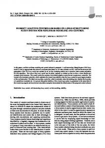
The results for speed, currents and voltages are shown in the figure 4, 5 and 6, respectively. These are obtained for a low speed region of motor operation, which is specific for the direct-drive applications.
40
30
20
[rev/ min]
10
0
-10
-20
-30
0
0.5
1
1.5
2
2.5
3
3.5
4
Time [sec]
Figure 7. MCK243 system drive with BLDC motor
Figure 4. Rotor speed
i [A]
50
a
0
-50
0
0.5
1
1.5
2
2.5
3
3.5
4
0
0.5
1
1.5
2
2.5
3
3.5
4
0
0.5
1
1.5
2
2.5
3
3.5
4
i [A]
50
b
0
-50
MSK243 block diagram of is shown in figure 8. It also integrates the following power electronics peripherals – 12 PWM channels (out of which 9 are independent), three 16 bit multi-mode general purpose timers, 16 channel 10 bit ADC with simultaneous conversion capability, four capture pins, encoder interface capability, SCI, SPI, Watch Dog etc.
i [A]
50
c
0
-50
Time [sec]
Figure 5 Motor phase currents 4
Va* [V]
2
x 10
0
-2
V * [V]
2
0 4 x 10
0.5
1
1.5
2
2.5
3
3.5
4
0 4 x 10
0.5
1
1.5
2
2.5
3
3.5
4
b
0
-2
0
c
V * [V]
2
-2
0
0.5
1
1.5
2
2.5
3
3.5
4
Time [sec]
Figure 6. Motor phase voltages
5. DSP BASED SPEED CONTROLLER A DSP based controller using a TMS320 F243 is utilized to implement a three-phase BLDC motor drive. It includes basic motor control with closed loop speed control. Figure 7 shows the overall system drive that wee have used for the experimental results (a Pittman BLDC 3400 series and a MCK243 Technosoft controller).
Figure 8. MCK240 block diagram Six PWM channels (PWM1 through PWM6) control the three-phase voltage source inverter. For efficient energy delivery to the motor, it is important that the correct inverter-switching scheme is employed. Space vector pulse width modulation is one such switching scheme that offers definite benefits over simpler and less efficient schemes like Sine PWM. It has been shown that SVPWM has a higher DC bus utilization and reduced harmonic copper losses. For a given DC link voltage output, SVPWM has the effect of boosting power output of a three-phase motor by 16% as compared to a Sine PWM fed motor. The entire application software is driven by an Interrupt service routine (ISR). The main code (i.e. background loop) consists simply of TMS320C243 peripheral initialization (e.g. PLL, Watchdog, Interrupt control & Event manager). The remainder of the code is taken up entirely by PWM_ISR.
omg[YR]
RPM
omg_ref[YR]
20 10 0 -10
i_a
-20
0
i_q_ref 75
150
225
300
375
Acquisition time Figure 9. Data acquisitions. – rotor speed, phase-a current and i_q ref curent
This ISR is invoked every 100uS (10KHz) by the Period event flag on Timer 1 of the Event manager. The following three steps are needed to generate the SVPWM waveform: • Generating the appropriate reference voltage vector. • Transforming the reference voltage vector to the set of appropriate switching variables a, b, and c. The software was written in C and assembly and is less than 6KW of program space. The on chip flash of the controller stored the program. Experimental results are presented in figure 9.
CONCLUSIONS This paper proposed an adaptive speed controller for the brushless DC motor drive. The controller structure include also a load-torque estimation in order to follow a speed reference. Design procedure is based on the field-oriented control and the controller itself consists of a two degree of freedom speed controller and a feed-forward load-torque compensator. The parameters of the first part are adjusted adaptively by a second-order least-squares estimator The second component is based on a first-order least-squares estimator for the load torque. Simulation and experimental results show that the proposed controller can achieve accurate velocity servo tracking in the presence of load disturbance and plant parameter variations
REFERENCES [1] K. J. Astrom and B. Wittenmark, Adaptive Control, Reading, MA, Addison Wesley, 1989. [2] Y. P. Yung and C. F. Fang, Adaptive speed control of AC servo induction with on-line load estimation, in Conference Rec. R.O.C. Automatic Control Conf., Taiwan, 1994, pp481-486. [3] C. Rusu, “DSP based robust controller of BLDC servo motor”, DAS2004 Proceedings, of the 7th International Conference on Development and Application Systems, 27-29 May, 2004 Suceava, ROMANIA, pp.167-171. [4] Spectrum Digital Inc., 504706-0001 Rev. A, “F24X DSK User Manual”, July 1999, 10853 Rockley Road Houston, TX, USA. [5] The MathWorks Web site, “Embedded Target for the TI TMS320C2000™ DSP Platform”, For Use with Real-Time Workshop. [6] Duane C. Hanselman , “Brushless Permanent Magnet Motor Design”, from, Ed Mc Graw Hill, 1994. [7] T.J.E. Miller, “Brushless Permanent Magnet and Reluctance Motor Drives” from Oxford Science publications, ISBN 0-19-859369-4, 1993. [8] Wang, Fei, ”Sine-triangle versus Space-vector modulation for three-level PWM voltage-source inverters”, IEEE trans on ind app, vol 38, no 2, mar/apr 2002 [9] Texas Instruments application note, ”Digital signal processing solution forpermanent magnet synchronous motor”, USA, 1996.