for the Bridgeless Power Factor Correction (PFC) converter. The control approach is .... during positive and negative half cycle of input voltage are shown in Figs.
International Review of Electrical Engineering (I.R.E.E.), Vol. 6, N. 2 March-April 2011
DSP Microprocessor Based-On Power Factor Correction to Improve Power Quality of Converters Using Predictive Control Ahmet Karaarslan1, Ires Iskender2
Abstract In this study, the predictive control approach is adapted to the current control strategy for the Bridgeless Power Factor Correction (PFC) converter. The control approach is developed to eliminate the input line current harmonics of the PFC converter without needing for the current sampling. In this approach, the zero crossing points of the input voltage are detected using DSP microprocessor. A sinusoidal signal is generated based on the detected points and used as a reference to control the converter switch to obtain unity power factor and lower input current Total Harmonic Distortion (THD). An adaptive digital FIR filter is designed and embedded into the control loop cancel the effects of noises and distortions on the output voltage. The feed forward technique is also used in the control algorithm by taking into account the maximum value of the input voltage. The implementation of feed forward and adaptive digital filter into the control algorithm improves the converter performance. The average current control (ACC) loop is used in the converter operating in continuous conduction mode (CCM). The converter used in simulation and experimental studies is a bridgeless power factor converter. The conduction losses of the switches of this converter are lower comparing to the similar PFC converters. The simulation and experimental results show that the proposed control strategy works well and the unity power factor operation can be achieved with a wide input voltage and load variation ranges. The results are compatible with IEC 61000-3-2 Current Harmonic Standard. Copyright © 2011 Praise Worthy Prize S.r.l. - All rights reserved.
Keywords: AC/DC Converters, Adaptive Digital FIR Filter, Bridgeless Converter, Power Factor Correction, Power Quality, Predictive Control
L=La+Lb C0 S1 and S2 vin(t) v0(t) Ts iL(t) iref(t) t=kTs (k)
Nomenclature THD PFC V0f(s) e(s) Vref w(k) k N C D LMS q fs fline ACC BCC PCC HCC FIR DSP CCM RL
Total Harmonic Distortion Power Factor Correction Adaptive filter output signal Error signal Reference signal Weight vector Time index Order of filter Mean-square error NxN autocorrelation matrix Nx1 cross-correlation vector Least Mean Square Convergence factor Switching frequency Line frequency Average Current Control Boundary Current Control Peak Current Control Hysteresis Current Control Finite Impulse Response Digital Signal Processor Continuous Conduction Mode Load
Input inductances Output capacitor IGBTs Input voltage Output voltage Switching period Input line current Reference current kth sampling instant Gradient at the nth iteration Expectation operator
I.
Introduction
Power quality has become a real problem over the last decade due to the ever increasing use of power electronics and sensitive load equipment. A poor power quality can damage or degrade the equipments such as computers and electronic devices used widely nowadays. This problem causes interruption of important industrial processes and hence economic losses [1]-[3]. High frequency switching converters are important power electronics devices widely used in a variety of power quality applications. In recent years, there have been increasing demands for high power
Manuscript received and revised March 2011, accepted April 2011
Copyright © 2011 Praise Worthy Prize S.r.l. - All rights reserved
512
Ahmet Karaarslan, Ires Iskender
voltage. The dynamic performance of system decreases when any change occurs at the input voltage. In [21], the duty cycles are calculated offline based on the power balance equation of single-phase boost topology. The calculated duty cycles are stored in the memory and used to control the duty cycle of the switch to achieve power factor correction. Though this method has an advantage such that the switching frequency of the PFC does not directly depend on the processing speed of the microprocessor, the controller has a poor robustness due to using the offline calculated duty cycles. These disadvantages are removed in the proposed study where the inductor current is estimated using the information taken from the input and output voltages. In addition, in this study an adaptive digital FIR filter is also added into the DSP software to control and to speed up the output voltage response to load variations and to eliminate almost the typical output voltage noises and overshoots [27], [28]. The feed-forward is also introduced in the proposed PFC control algorithm using maximum value of the input voltage to improve the converter performance. The proposed control technique enables the input current to be synchronized with the fundamental content of the input voltage. The advantages of the proposed control strategy can be summarized as, i-needing to measure only two parameters instead of three in conventional type PFC converters, ii- speeding up the output voltage response to load variations and eliminating almost the typical output voltage noises and overshoots using adaptive digital FIR filter, iii- improving the converter performance using feedforward algorithm in which the maximum value of the input voltage is used in control algorithm [29]. The simulations and experimental studies show that the control approach works well and unity power factor can be achieved with wide input voltage and load variation range. This study is in a good proper with IEC 61000-3-2 Current Harmonic Standard. In this paper, the principle of the bridgeless PFC converter description is presented in section II. The predictive control strategy for digital PFC implementation is described in detail in section III. The simulation and experimental results are presented in section IV and V, respectively. The conclusion is given in the last section.
factor and lower THD in the current drawn from the utility. With the requirements of power quality, PFC algorithm has been an active research topic in power electronics, and significant efforts have been made on the developments of the PFC converters [4]-[6]. The main task of the controller in unity-power-factor converters must be to guarantee a sinusoidal input current shape in phase with the line voltage and maintain the output voltage around a specific average value with low ripple. It is desirable to achieve a fast dynamic response of the output voltage without causing input current distortion [7]. Besides, the efficiency of various circuit topologies has gained interest among unity power factor converters. These converters should also be able to operate at unity power factor operation, the results of which comply with several standards such as IEC 61000-3-2 being a European standard for current harmonics contents [8]. Efforts have been done to improve the performance of switching mode power supplies by implementing control strategy to remove the harmonic contents of the input current. Generally, this is accomplished by using digital PFC converters. The digital controllers have many advantages over the analog controllers due to their programmability, adaptability, less susceptibility to environmental variations, no temperature and aging effect, and more immunity to the input voltage distortion. It also reduces the size of the power circuit by containing the complexity of control system within the software [9]-[13]. Different control techniques such as ACC, PCC, BCC and HCC can be used in the switched mode power supply to achieve unity power factor [14]-[17]. Most digital implementations for PFC are based on average current control mode. The ACC technique is also used in this study due to its superior characteristics such as good tracking performance of the inductor current and no slope compensation and noise immunity [18], [19]. Normally, in conventional power factor converters the output voltage is measured and compared with the reference voltage to obtain reference current. The generated reference current is compared with the measured inductor current to adjust the duty cycle of the converter switch. In these converters the output voltage of converter, inductor current, and the input ac voltage should be measured to adjust duty cycle to obtain unity power factor operation. Using predictive control strategy makes it possible to provide unity power factor by measuring only the input and output voltages without needing to measure the inductor current. The control strategy is based on the prediction of the inductor current at each sampling instant, not feedback to achieve unity power factor. The predictive control method is used in different applications such as single-phase PFC circuits [20], [21], ac drives and active filters [22] and single/three phase inverters [23]-[26]. In [20], the input voltage is estimated using predictive control method. The proposed solution is based on a multi loop structure with an internal deadbeat current control and an outer voltage control. The switch current and output voltage measurements are used to estimate the input
II.
The Converter Configuration
There are different topologies used in PFC converters. The topology used in this study, is a Bridgeless PFC converter and is shown in Fig. 1. An important advantage of this topology over the similar PFC converters is that the conduction losses of the semiconductor switches are lower. This is due to minimum number of semiconductor switches in the current path at any instant of operation which is two [30]-[32]. This topology is composed of two single-phase boost converters without input rectifier as used in other PFC circuits. The output voltage regulation and the current control are achieved by controlling the switch S1 during positive
Copyright © 2011 Praise Worthy Prize S.r.l. - All rights reserved
International Review of Electrical Engineering, Vol. 6, N. 2
513
Ahmet Karaarslan, Ires Iskender
and S2 during negative half cycles of the ac input voltage.
C0
dv0 dt
iL
v0 RL
(4)
The equations corresponding to negative half cycle of ac input voltage are the same as those for positive half cycle (Equations (1)-(4)). The models corresponding to and time intervals of tk t tk d k Ts tk d k Ts t tk respectively: diL dt dv0 dt
Fig. 1. Bridgeless PFC converter topology
The different operating modes of the converter in CCM during positive and negative half cycle of input voltage are shown in Figs. 2(a) and 2(b), respectively.
diL dt dv0 dt
1
are given in Equations (5)-(6),
1 L vin 0
1 L vin 0
0 0
0 1 C0
0 1 RL C0 1 L 1 RL C0
iL v0
iL v0
(5)
(6)
III. Proposed Control Approach
(a)
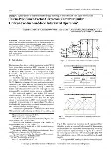
Predictive control is a wide class of controllers that have been found rather recent applications in power converters. The control approach based on the predictive algorithm is shown in Fig. 3. In this control approach, the input and output voltages (vin, v0) are feedback signals and the gate signals of the switches (S1, S2) are the output of the controller. The error between the measured and reference output voltages is processed in a PI controller to obtain the magnitude of reference current. The generated reference current is used in predictive control algorithm instead of the inductor current to obtain duty cycle of the switches. In this study, an adaptive digital FIR filter is also added into the DSP software to eliminate the output voltage noises and distortions. So, the system stability under disturbance of uncertain parameters and load variation can be guaranteed. To speed up the output voltage controller and to achieve better dynamic and steady state characteristics, the input voltage feedforward is introduced in the predictive algorithm to compensate the duty cycle. It stabilizes the PFC system and improves its dynamic performance. Fig. 4 shows the waveforms of the vin(t), iL(t), iref(t) and v0(t). The reference current should be proportional to the input line voltage to improve current waveform and power factor. It should be noted that there is an approximation in the predictive algorithm. The average current in each switching cycle should follow the reference current in Fig. 4. The instantaneous current iL(k) is forced to track the reference current, iref(k). The duty cycle of predictive control can be derived as in the following.
(b)
Figs. 2. Equivalent circuits of the converter for on/off states of the switches during: (a) Positive half cycle, (b) Negative half cycle
The mathematical model of the converter during positive half cycle of ac input voltage is given in Equations (1)-(2). During the on state of the switch S1 the current flows through switch S1 and the body diode of S2. During this period, energy is stored in the inductors and the capacitor discharges through the load ( tk t tk d k Ts ): vin
C0
L
diL dt
dv0 dt
v0 RL
(1)
(2)
During off state of switch S1, the current flows through D1, the parallel connected capacitor and load and the body diode of S2 ( tk d k Ts t tk 1 ):
vin
v0
L
diL dt
(3)
Copyright © 2011 Praise Worthy Prize S.r.l. - All rights reserved
International Review of Electrical Engineering, Vol. 6, N. 2
514
Ahmet Karaarslan, Ires Iskender
iL k R k
d k
iref k , vo k u k Vm 2 vof k
vof k , vin (k )
, iref k
A
R k sin wline tk
R k 1 sin wline tk
vof k
vof k
R k sin wline tk
A ,
L
1
(9)
Ts
vof k The predictive control presents several advantages that make it suitable for the control of power converters: Concepts are intuitive and easy to understand, it can be applied to a variety of systems, constraints and nonlinearities can be easily included, multivariable case can be considered, and the resulting controller is easy to implement. It requires a high amount of calculations, compared to classic control scheme; however, the fast microprocessors available today make possible the implementation of predictive control [33]. The noises generated by different sources should be filtered to improve the performance of the system. An adaptive digital filter is a computational device that iteratively models the relationship between the input and output signals of the filter. An adaptive filter self-adjusts the filter coefficients according to an adaptive algorithm. The overall structure for an adaptive digital FIR filter is shown in Figs. 5.
Fig. 3. The scheme of digital predictive control algorithm for the proposed PFC converter
Fig. 4. Current and voltage waveforms of (k-1)th, kth and (k+1)th sampling intervals for Ts
For tk L
diL dt
t
tk
d k Ts & tk
d k Ts vin k
d k Ts
vin k
t
vo k
tk 1 : (a)
1 d k Ts (7)
diL d k Ts vin k vin k Ts dt d k Ts vin k vo k Ts
L
d k Ts vo k iL k 1 1
d k
L
iL k
vin k Ts
vo k
vo k Ts
vin k
vo k
d k Ts vo k
iL k 1
iL k
(b)
L
Ts
vo k
Figs. 5. (a) Simplified block diagram of adaptive digital FIR filter, (b) Digital FIR Filter with time dependent coefficients
(8)
Copyright © 2011 Praise Worthy Prize S.r.l. - All rights reserved
International Review of Electrical Engineering, Vol. 6, N. 2
515
Ahmet Karaarslan, Ires Iskender
change proportional to the negative gradient of meansquare-error performance surface:
In general, adaptive filters consist of two basic parts: i-the filter applying the required processing on the incoming signal (v0(s)) which is to be filtered, ii- and an adaptive algorithm adjusting the coefficients (w(k)) of that filter to somehow improve its performance. v0(s) is the input signal to a linear filter, V0f(s) is the corresponding output signal, Vref is an reference signal to the adaptive filter, e(s) is the error signal that denotes the difference between Vref and Vof(s). In this application, digital FIR filter structure is implemented (Fig. 5(b)). In Fig. 5(a), an adaptive algorithm adjusts the coefficients of the linear filter iteratively to minimize the power of e(s). Therefore, the control algorithm will not be affected by output voltage distortions. The implementation of an adaptive filter output signal Vof(k) is given by:
w k 1
wT k v0 k
wi k v0 k i
assuming squared error, e 2 k
weight v0 k
w0 k
vector, v0 k
w1 k the
v0 k 1
... wN input
... v0 k
1
T
k
N 1
T
k
w k 1
is
Vref
Vof k
(11)
w0 k Initialization
wT k Cw k 2 wT k D
where C
v0 k v0 k
0 or w0 k
randn N ,1
if no prior
knowledge of w k is available
Data
(13)
To compute
v0 k
v0 k
, if Vref
v0 k 1
v0 k
v0 k 1
, if Vref
v0 k
v0 k 1
v0 k
...
2
v0 k
...
N
1
v0 k
N
T
w k 1 estimated weights at time k 1 k
T
(16)
jmin, the minimum value of error criterion
(12)
where, denotes the expectation operator. Substituting Vof(k) from Equation (10) into Equation (11), gives Equation (13) as: Vref 2
2qe k v0 k
TABLE I ADAPTIVE DIGITAL FIR FILTER ALGORITHM N- order of filter Parameters q- convergence factor
The input vector v0(k) and e(k) are used to update the adaptive coefficients according to a criterion that is to be minimized. The criterion employed in this section is the ( ): e2 k
w k
The evolution of the output error and the weight coefficients implemented into the control algorithm are shown in Table I. In the filter design process, the next step is to estimate the coefficient and internal data word lengths needed to meet the adaptive filter specifications.
T
denotes transpose, k is the time index and N is the order of filter. The adaptation algorithm uses the error signal: e k
(15)
2e k v0 k
w k
Substitution of this instantaneous gradient estimate into Equation (14) yields the Widrow-Hoff LMS algorithm as [28]:
is the
,
as an estimate of the
e2 k
(10)
vector
(14)
mean square error in Equation (12). Thus, the expression for the gradient estimate can be simplified as:
i 0
where, w k
k
q is the convergence factor controlling the stability of filter. For the LMS algorithm, the k , is estimated by
N 1
Vof k
w k q
1
Do
is the NxN autocorrelation
e k
matrix, which indicates the sample-to-sample correlation within a signal, and D Vref v0 k is the Nx1 cross-
Vref
Computation
w k 1 k
correlation vector, which indicates the correlation between the desired signal Vref and the input signal vector v0(k). In order to avoid the complicated computation, a widely used LMS algorithm is used as an alternative algorithm that adapts the weights on a sample-by-sample basis. This algorithm is a more practical method to find close approximate solutions to the weights in real time. The LMS algorithm uses the steepest descent method in which the next weight vector w(k+1) is increased by a
k
T
w
w k
k v0 k 2 qe k v0 k
1
While j
jmin
This control approach is suitable for digital implementation of PFC converters. In the proposed control PFC strategy the duty cycle required to achieve unity power factor is calculated at each switching cycle using a pure reference sinusoidal signal generated based on the detected zero crossing points, frequency
Copyright © 2011 Praise Worthy Prize S.r.l. - All rights reserved
International Review of Electrical Engineering, Vol. 6, N. 2
516
Ahmet Karaarslan, Ires Iskender
calculation, feed forward and adaptive digital FIR filter design. The proposed PFC control approach guarantees the sinusoidal current waveform under the wide load and input voltage variations.
IV.
to 600 W (change from half load to full load). The power factor and THD of input current for output power values of 600 W/300 W are 0.996/0.992 and 4.2%/4.9%, respectively.
Simulation Studies
The simulation study is performed by MATLAB/ Simulink program using predictive control approach applied on PFC converter. The parameters used in simulations and experiments are given in Table II. TABLE II PARAMETERS USED IN SIMULATIONS AND EXPERIMENTS Output Power P0 600 [W] Output voltage
v0
400 [V]
Input voltage
vin, fline
Switching frequency
fs
Fast Diodes
D1, D2
IGBTs
S1, S2
IXGH24N60-CD1
Inductances value
La ,Lb
2 [mH]
Output Capacitor
C0
220 [Vrms,50 Hz] 50 [kHz]
(a)
DSEI6012A
500 [µF]
Using the sinusoidal signal generated by the DSP based on the zero crossing points of the input voltage eliminates the effects of the input voltage distortion on the input current. In the following simulations the required current limits indicated in IEC 61000-3-2 standard (Table III) are taken into account. Fig. 6 shows the simulation results of the input ac line current, input voltage and output voltage waveforms corresponding to predictive control approach. For this case of operation the input voltage rms value, output power and the input ac frequency are 220 Vrms, 600 W, and 50 Hz, respectively. The power factor for this case is equal to 0.996 and the THD of input current is 4.2%.
(b) Figs. 7. Input line voltage, output voltage and the line current for load changes: (a) From 600 to 300 W, (b) From 300 to 600 W TABLE III IEC 61000-3-2 CURRENT HARMONIC LIMITS Harmonics Class-A Class-B Class-C Class-D [n] [A] [A] [%] [mA/W] Odd Harmonics 3
2.3
3.45
30x
3.4
5 7
1.14
1.71
10
1.9
0.77
1.155
7
1.0
9 11
0.40
0.60
5
0.5
0.33
0.495
3
0.35
13
0.21
0.315
3
3.85/13
15 n 39
0.15x15/n
0.225x15/n
3
3.85/n
Even Harmonics
Fig. 6. Simulation result of current and voltage waveforms
Figs. 7 show the simulation results of the converter for the case when the output power of the converter is changed from 600 to 300 W (change from full load to half load) and then again the power is changed from 300 Copyright © 2011 Praise Worthy Prize S.r.l. - All rights reserved
2
1.08
1.62
2
-
4
0.43
0.645
-
-
6
0.30
0.45
-
-
8 n 40
0.23x8/n
0.345x8/n
-
-
International Review of Electrical Engineering, Vol. 6, N. 2
517
Ahmet Karaarslan, Ires Iskender
The analog signals of the bridgeless PFC converter are continuous in time and it is necessary to convert this to a flow of digital values. It is therefore required to define the rate at which digital values are sampled from the analog signal. The instantaneous signals vin, and v0 are sensed and conditioned by the DSP microprocessor via two ADC channels, ADCINA0 and ADCINA1, respectively. The sampling time for these signals is 40 µs. The PI controllers, Kp and Ki are chosen by Ziegler Nichols method rule. Fig. 10 shows the input voltage, output voltage and the input ac current of the PFC converter used in this study. The input voltage and the output power are 220Vrms/50 Hz and 600 W, respectively. The power factor and THD of input current for the given operating conditions are 0.994 and 5.0%, respectively.
Figs. 8 show the simulation results of the converter for the case when the input voltage of the converter is changed from 220 to 180 Vrms and vice versa. The output power is kept constant (600 W) during the input voltage change. The input line voltage, output voltage and the input ac current waveforms corresponding to two different changes are shown in Figs. 8.
(a)
Fig. 9. Bridgeless PFC converter controlled by DSP microprocessor
(b) Figs. 8. Output voltage and input line current for input voltage changes: (a) from 220 to 180 Vrms, (b) from 180 to 220 Vrms
Fig. 8(a) and 8(b) show the results obtained from changing the rms value of the input line voltage from 220 to 180 V and 180 to 220 V, respectively. The input power factor and THD of the converter corresponding to input voltages 220/180 V are 0.996/0.993 and 4.2%/4.7%, respectively.
V.
Experimental Studies
In this section, the results of the experiments obtained from applying predictive control approach on a bridgeless PFC converter operating at CCM mode are analyzed. The ACC technique was used in the experiments. The control of the converter for different cases of operation is achieved using DSP TMS320F2812. The LEM LV25-P was used in taking data from the input and output voltages. The experimental set up used in the laboratory is shown in Fig. 9. The values of the converter parameters used in the experiments are the same as used in the simulation studies and are given in Table II.
Fig. 10. Input voltage, output voltage, and the input ac current waveforms
The effects of load change on the converter performance are analyzed in Figs. 11. In this analysis the input voltage rms value is 220 V and the output voltage set value is 400 V. The input voltage, output voltage and the input ac current responses for a decrease of 300 W in load (change from 600 to 300 W) and for an increase of
Copyright © 2011 Praise Worthy Prize S.r.l. - All rights reserved
International Review of Electrical Engineering, Vol. 6, N. 2
518
Ahmet Karaarslan, Ires Iskender
-
300 W (change from 300 to 600 W) are shown in Figs. 11(a) and 11(b), respectively. The power factor and THD of input current for output power values of 600 W/300 W are 0.994/0.990, and 5.0%/5.8%, respectively.
-
The reflection of the input voltage distortions to the output voltage is eliminated by adaptive digital FIR filter, The proposed controller can work for all line frequencies of input voltage, The feed forward is implemented to the control strategy by using the peak value of the input voltage in the control loop to improve the dynamic performance of the system.
(a)
(a)
(b) Figs. 11. Output voltage, line current and input voltage for load change: (a) From 600 to 300 W, (b) From 300 to 600 W
Similar to simulation study, the effects of the input voltage changes on the converter performance are analyzed and shown in Figs. 12. In this part of experiment the output power is kept constant at 600 W and the input line voltage rms value changes from 220 to 180 V (Fig. 12(a)) and from 180 to 220 Vrms (Fig. 12(b)). The input power factor and THD of the input current for input voltage value of 220/180 Vrms are 0.994/0.991 and 5.4%/5.0%, respectively. The magnitudes of the harmonics contents of the input line current corresponding to simulation and experimental studies are compared with the corresponding harmonics given in IEC 61000-3-2 (Fig. 13). It is shown from the figure that the magnitudes of harmonics contents of both simulation and experimental studies are less than the magnitudes of the corresponding harmonics given in standard. The advantages of the proposed control method as compared to the conventional one are given as: - The system is not effected by input voltage distortions and the THD of input current is lower than conventional control method,
(b) Figs. 12. Output voltage and input line current for input voltage changes: (a) from 220 to 180 Vrms, (b) from 180 to 220 Vrms
Fig. 13. Comparing input current harmonics values with those given in IEC 61000-3-2
The disadvantages of the proposed control method are given as:
Copyright © 2011 Praise Worthy Prize S.r.l. - All rights reserved
International Review of Electrical Engineering, Vol. 6, N. 2
519
Ahmet Karaarslan, Ires Iskender
-
Calculation of the sampling frequency is difficult, Control procedures are complex, Using the microprocessor, the proposed system is expensive compared to other systems. The experimental results show that the control approach can achieve a near unity power factor with lower THD of input current under input voltage and load change conditions.
[4]
[5] [6]
[7]
VI.
Conclusion
[8]
In this paper, the performance of the control strategy applied on the bridgeless PFC is analyzed. The input and output voltages of the converter are measured and evaluated using predictive control algorithm to adjust the duty cycles of the converter switches. It is a very powerful tool and presents a great flexibility to control different kinds of variables and is a very attractive alternative for the control of power converters. An adaptive digital FIR filter was also designed and implemented in the control program to reject unwanted signals, noises and distortions. To achieve better dynamic and steady state characteristics, the input voltage feed-forward was introduced in the control program. Contrary to conventional PFC converters in which the input, output voltages and the inductor current are measured, in the proposed control strategy the inductor current is estimated and there is no need to measure this parameter. The input current is forced to track the sinusoidal signal generated with the same phase angle of input voltage using DSP microprocessor. The simulation study of the converter was carried out for different cases of operation such as load change and input voltage distortion using Matlab/Simulink program. The results obtained from the experiments carried out in the laboratory for the same conditions of the simulation study verify the results of the simulation considering the performance criteria such as input power factor, input current THD and output voltage control. The system satisfies the conditions of IEC 6100032 current harmonics standards successfully.
[9]
[10]
[11]
[12]
[13]
[14]
[15]
[16]
[17]
[18]
[19]
Acknowledgements The authors would like to thank TUBITAK for financial support in part to complete this research work (Project Number: 108E081).
[20]
[21]
References [1]
[2]
[3]
[22]
T. Chatchanayuenyong, Power Quality Improvement Using a Sliding Mode Control of a Series Active Filter, American Journal of Applied Sciences, vol. 8, 2008, pp. 10291033. M. Taherbaneh, H. Ghafoorifard, A. H. Rezaie, M. B. Menhaj, K. Rahimi, Efficiency Improvement of Series-Connected Boost Converters, International Review of Electrical Engineering, vol. 5, no. 5, 2010, pp. 1887-1897. Bor-Ren Lin, Huann-Keng Chiang, Ruei-Song Wu, Analysis and Implementation of a Double Buck-Boost Converter with Power
[23]
Copyright © 2011 Praise Worthy Prize S.r.l. - All rights reserved
Factor Correction, International Review of Electrical Engineering, vol. 5, no. 6, 2010, pp. 2586-2592. R. Redl, L. Balogh, and N. O. Sokal, A new family of single-stage isolated power-factor correctors with fast regulation of the output voltage, in Proc. PESC94, 1994. Y. Jiang and F. C. Lee, Single-stage single-phase parallel power factor correction scheme, in Proc. PESC, 1994. M. Daniele P. K. Jain, and G. Joos, A single-stage power-factorcorrected AC/DC convertor, IEEE Trans. Power Electron., vol.14, 1999, pp. 10461055. L. Huber, J. Zhang, M. M. Jovanovic, and F. C. Lee, Generalized topologies of single-stage input-current-shaping circuits, IEEE Transaction on Power Electronics, vol. 16, 2001, pp. 508513. Electromagnetic Compatibility (EMC), Limits for Harmonic Current Emissions (Equipment input current 16A per phase), IEC Standard IEC 61000-3-2, Part 3, Section 2, 2009. M. Fu, Q. Chen, A DSP based controller for power factor correction in a rectifier circuit, in Proc. 16th Annual IEEE Applied Power Electronics Conf. Expo., 2001. S. Buso et al., Simple digital control improving dynamic performance of power factor pre-regulators, IEEE Trans. Power Electron., vol. 13, 1998, pp. 814823,. A. Prodic, J. Chen, D. Maksimovic, and R.W. Erickson, Digitally controlled low-harmonic rectifier having fast dynamic responses, in Proc. IEEE APEC02 Conf., 2002. S. Bibian and H. Jin, Digital control with improved performance for Boost power factor correction circuits, in Proc. 16th Annu. IEEE Applied Power Electronics Conf. Expo, 2001. S. Kim and P. N. Enjeti, Control of multiple single phase PFC modules with a single low-cost DSP, in Proc. 18th Annu. IEEE Applied Power Electronics Conf. Expo, 2003. N. Kondrath, M.K. Kazimierczuk, Control current and relative stability of peak current-mode controlled pulse-width modulated dc-dc converters without slope compensation, IET Power Electronics, vol. 3, 2010, pp. 936946. A. Karaarslan and I. Iskender, The Comparison of Average and Hysteresis Current Mode Control Technique of Single-Phase Boost Power Factor Correction Converter, 6th International Conference on Technical and Physical Problems of Power Engineering, ICTPE10, 2010. L. Huber, B.T. Irving, M.M. Jovanovic, Open-Loop Control Methods for Interleaved DCM/CCM Boundary Boost PFC Converters, IEEE Transactions on Power Electronics, vol. 23, no.4, 2008, pp. 16491657. Xingwu Yang, Jianguo Jiang, Predictive Current Control of Three-phase PWM Rectifiers using Virtual Voltage Vectors, International Review of Electrical Engineering, vol. 5, no. 6, 2010, pp. 2578-2585. Ying Qiu, Liu, H. Xiyou Chen, Digital Average Current-Mode Control of PWM DCDC Converters without Current Sensors, IEEE Trans. on Industrial Electronics, vol. 57, no. 99, 2010, pp. 16. Y. Zhang, W. Xu, Y. Yu, The PFC with Average Current-Mode and Voltage Fuzzy Controller for The Output Voltage, IEEE II International Symposium on Intelligent Information Technology Application, 2008. Mattavelli, P., Spiazzi, G., Tenti, P., Predictive Digital Control of Power Factor Pre-regulators with Input Voltage Estimation Using Disturbance Observers, IEEE Transactions on Power Electronics, vol. 20, no.1, 2005, pp. 140147. W. Zhang, G. Feng, Y.-F.Liu, and B.Wu, A digital power factor correction (PFC) control strategy optimized for DSP, IEEE Trans. Power Electron., vol. 19, no. 6, Nov. 2004, pp. 14741485. K. Drobnic, M. Nemec, D. Nedeljkovic, V. Ambrozi, Predictive Direct Control Applied to AC Drives and Active Power Filter, IEEE Transactions on Industrial Electronics, vol. 56, no. 6, 2009, pp. 18841893. H. M. Kojabadi, B. Yu, I. A. Gadoura, L. Chang, and M. Ghribi, A novel DSP-based current-controlled PWM strategy for single phase grid connected inverters, IEEE Trans. Power Electron., vol. 21, no. 4, Jul. 2006, pp. 985993.
International Review of Electrical Engineering, Vol. 6, N. 2
520
Ahmet Karaarslan, Ires Iskender
[24] R. Kennel and A. Linder, Predictive control of inverter supplied electrical drives, in Proc. IEEE 31st Annu. Power Electron. Spec. Conf., 2000. [25] D. G. Holmes and D. A Martin, Implementation of a direct digital predictive current controller for single and three phase voltage source inverter, in Proc. Annu. Meeting IEEE Ind. Appl., 1996. [26] Lin, B.-R. and Chen, J.-J., Analysis and Implementation of Active Clamp PFC Sepic Converter, International Review of Electrical Engineering, vol. 4, no. 3, 2009, pp. 357-364. [27] S. Haykin, Adaptive Filter Theory (Prentice-Hall, Englewood Cliffs, NJ, 1991). [28] M. G. Bellanger, Adaptive Digital Filters and Signal Analysis (Marcel Dekker Inc., New-York and Basel, 1987). [29] Karaarslan A., Iskender I., A Novel Method In Power Factor Correction Circuits Using Average Current Control Technique and Digital Signal Processor, Journal of The Faculty of Engineering and Architecture of Gazi University, vol. 26, no. 1, 2011, pp. 193-203. [30] WY. Choi, JM. Kwon, EH. Kim, JJ. Lee, BH. Kwon, Bridgeless boost rectifier with low conduction losses and reduced diode reverse-recovery problems, IEEE Transactions on Industrial Electronics, vol.54, 2007, pp. 769780. [31] Kong P, Wang S, Lee FC, Common mode EMI noise suppression for bridgeless pfc converters, IEEE Transactions on Power Electronics, vol.23, 2008, pp. 291298. [32] L. Huber, Y. Jang, MM. Jovanovic Performance evaluation of bridgeless pfc boost rectifiers, IEEE Transactions on Power Electronics vol. 23, no. 3, 2008, pp. 13811389. [33] P. Cortes, M. P. Kazmierkowski, R.M. Kennel, D.E. Quevedo, J. Rodriguez, Predictive Control in Power Electronics and Drives, Transaction on Industrial Electronics, vol. 55, no. 12, 2008, pp. 43124324.
Ires Iskender received B.Sc. in Electrical Engineering from Gazi University in 1989, Ankara. He received M.Sc. and Ph.D. Degrees in Electrical Engineering from Middle East Technical University in 1991 and 1996, respectively. From 1989 to 1996 he worked as a research assistant in the Electrical and Electronics Engineering Department of Middle East Technical University, Ankara, Turkey. Since 1997 he has been with the Department of Electrical Engineering, Gazi University, where he is currently an associate professor. His interests include renewable energy sources, energy conversion systems, power electronics and electrical machines.
Authors information 1 2
Gazi University, Department of Industrial Technology Education. Gazi University, Department of Electrical-Electronics Engineering.
Ahmet Karaarslan received B.Sc. and M.Sc. degrees in Electrical and Electronics Engineering in 2002 and 2005 and the Ph.D. degree continues in Electrical & Electronics Engineering from Gazi University, Turkey, from 2005. From 2002 to 2006 he worked as a research assistant in the Computer Education Department of Gazi University. Since 2006 he has been with the Industrial Technology Department, Gazi University, where he is currently an instructor. His research interests are in the application of the circuits of power electronics, energy conversion systems, programming microprocessors, renewable energy sources, computer applications.
Copyright © 2011 Praise Worthy Prize S.r.l. - All rights reserved
International Review of Electrical Engineering, Vol. 6, N. 2
521